SFI SYSTEM DETAILS
-
FUNCTION OF MAIN COMPONENTS
-
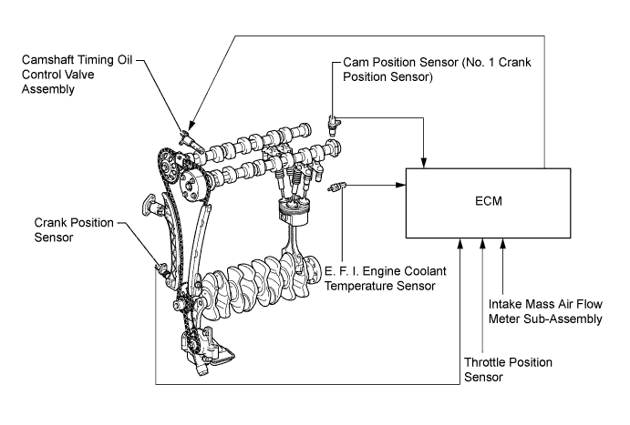
The main components of the engine control system are as follows.
Components Outline Quantity Function ECM 32-bit CPU 1 The ECM optimally controls the SFI, ESA, EGR and ETCS-i to suit the operating conditions of the engine in accordance with the signals provided by the sensors. Intake Mass Air Flow Meter Sub-assembly Hot-wire Type 1 This sensor has a built-in hot-wire to directly detect the intake air mass. Intake Air Temperature Sensor Thermistor Type 1 This sensor detects the intake air temperature by means of an internal thermistor. Crank Position Sensor
(Rotor Teeth)
Pick-up Coil Type
(36 - 2)
1 This sensor detects the engine speed and detects crank angle. Cam Position Sensor (No. 1 Crank Position Sensor)
(Rotor Teeth)
Magneto-Resistance Element (MRE) Type
(3)
1 This sensor performs cylinder identification and detects VVT angle. Throttle Body Assembly
-Throttle Position Sensor
Linear (Non-contact) Type 1 This sensor detects the throttle valve opening angle. Knock Control Sensor Built-in Piezoelectric Element Type (Flat Type) 1 This sensor detects the occurrence of the engine knocking indirectly from the vibration of the cylinder block caused by the occurrence of engine knocking. E.F.I. Engine Coolant Temperature Sensor Thermistor Type 1 This sensor detects the engine coolant temperature by means of an internal thermistor. Air Fuel Ratio Sensor (Bank 1, Sensor 1) Planar Type with Heater 1 As with the oxygen sensor, this sensor detects the oxygen concentration in the exhaust emission. However, it detects the oxygen concentration in the exhaust emission linearly. Oxygen Sensor (Bank 1, Sensor 2) Cup Type with Heater 1 This sensor detects the oxygen concentration in the exhaust emission by measuring the electromotive force which is generated in the sensor itself. Fuel Injector Assembly 12-hole Type 4 The fuel injector assembly is an electromagnetically-operated solenoid with a nozzle which injects fuel in accordance with signals from the ECM.
-
-
SYSTEM CONTROL
-
System Control Table
-
The engine control system has the following systems.
Components Function Sequential Multiport Fuel Injection (SFI)
-
An L-type SFI system is used, the intake air mass is detected with a hot-wire type intake mass air flow meter sub-assembly.
-
The fuel injection system is a sequential multiport fuel injection system.
-
Fuel injection takes 2 forms:
-
Synchronous injection: always takes place with the same timing in accordance with the basic injection duration and an additional correction based on the signals provided by the sensors.
-
Non-synchronous injection: takes place at the time an injection request based on the signals provided by the sensors is detected, regardless of the crankshaft position.
-
Synchronous injection is further divided into grouped injection during a cold start, and independent injection after the engine is started.
Electronic Spark Advance (ESA)
-
Ignition timing is determined by the ECM based on signals from various sensors. The ECM corrects ignition timing in response to engine knocking.
-
This system selects the optimal ignition timing in accordance with the signals received from the sensors and sends (IGT) ignition signals to the igniters.
Electronic Throttle Control System-intelligent (ETCS-i) Optimally controls the opening angle of the throttle valve in accordance with the accelerator pedal input and the engine and vehicle conditions. Variable Valve Timing-intelligent (VVT-i) Controls the intake camshaft to an optimal valve timing in accordance with the engine operating conditions. Cooling Fan Control Cooling fan operation is controlled by signals from the ECM based on the engine coolant temperature, air conditioning operation conditions, and hybrid system coolant temperature. Water Pump Control Engine water pump assembly operation is controlled by signals from the ECM. Fuel Pump Control
-
Fuel pump operation is controlled by signals from the ECM.
-
The fuel pump is stopped when the SRS airbags deploy.
Air Fuel Ratio Sensor and Oxygen Sensor Heater Control Maintains the temperature of the air fuel ratio sensor or oxygen sensor at an appropriate level to increase the ability of the sensors to accurately detect the oxygen concentration. Exhaust Gas Recirculation (EGR) Control
(For details, Click here
Based on the signals received from the sensors, the ECM determines the EGR volume in accordance with engine operating conditions. Evaporative Emission Control The ECM controls the purge flow of evaporative emissions (HC) from the canister in accordance with engine operating conditions. Fail-safe When the ECM detects a malfunction, the ECM stops or controls the engine according to the data already stored in memory. Diagnosis When the ECM detects a malfunction, the ECM records the malfunction and information that relates to the fault. -
-
-
Variable Valve Timing-intelligent (VVT-i) System
-
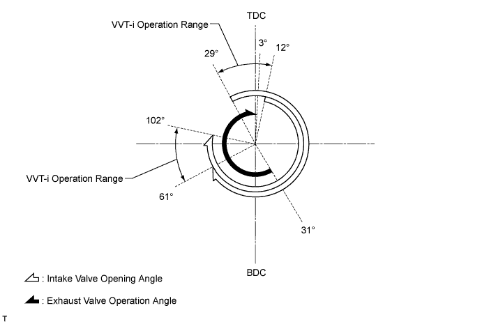
The VVT-i system is designed to control the intake camshaft within a range of 41° (of Crankshaft Angle) to provide valve timing that is optimally suited to the engine operating condition. This improves torque in all engine speed ranges as well as increasing fuel economy, and reducing exhaust emissions.
-
-
Cooling Fan Control
-
The cooling fan control system achieves an optimal fan speed in accordance with the engine coolant temperature, inverter water temperature, vehicle speed, engine speed, and air conditioning operating conditions.
-
-
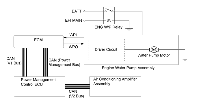
Water Pump Control
-
The ECM regulates the amount of the ECM regulates the amount of engine coolant circulation to suit the engine operating conditions. The ECM bases this control on signals such as the engine coolant temperature, vehicle speed and engine speed. As a result, the engine will be warmed up more quickly, and cooling loss will be reduced as well.
-
-
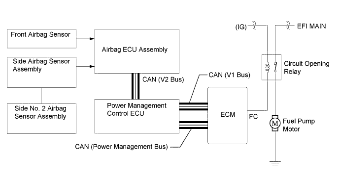
Fuel Pump Control
-
A Fuel cut function is used to stop the pump once when any of the SRS airbags have deployed. When the power management control ECU detects the airbag deployment signal from the airbag ECU assembly, it transmits an engine off signal to the ECM. Upon receiving this signal, the ECM turns off the circuit opening relay.
-
-
-
CONSTRUCTION
-
ECM
-
The ECM is installed in the engine compartment. As a result, the wiring harness has been shortened, thus realizing weight reduction.
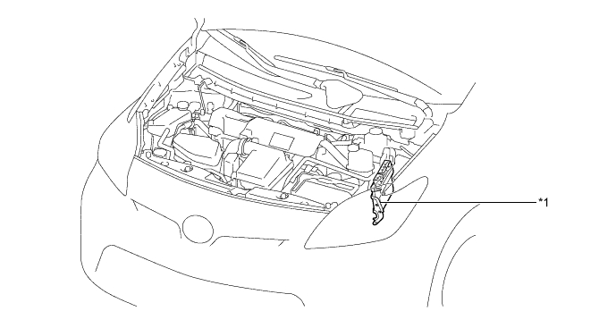
Text in Illustration *1 ECM - -
-
-
Crank Position Sensor and Cam Position Sensor (No. 1 Crank Position Sensor)
-
A pick-up coil type crank position sensor is used. The timing rotor of the crankshaft consists of 34 teeth with 2 teeth missing. The crank position sensor outputs the crankshaft rotation signals every 10°, and the missing teeth are used to determine top-dead-center.
-
A Magneto-Resistance Element (MRE) type cam position sensor (No. 1 crank position sensor) is used. To detect the camshaft position, a timing rotor that is part of the camshaft is used to generate 3 pulses (3 high output, 3 low output) for every 2 revolutions of the crankshaft.
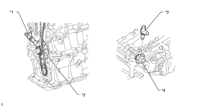
Text in Illustration *1 Crank Position Sensor *2 Crankshaft Timing Sprocket *3 Cam Position Sensor (No. 1 Crank Position Sensor) *4 Timing Rotor 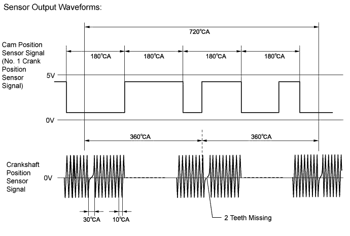
-
The MRE type sensor consists of a magnet and a sensor with a built-in MRE. The direction of the magnetic field changes due to the profile (protruding and non-protruding portions) of the timing rotor, which passes by the sensor. As a result, the resistance of the MRE changes, and the output voltage to the ECM changes to either high or low. The ECM detects the cam position based on this output voltage.
-
The differences between an MRE type sensor and a conventional pick-up coil type sensor are as follows.
Item Sensor Type MRE Pick-up Coil Signal Output Constant digital output starts from low engine speeds. Analog output changes with the engine speeds. Crankshaft Position and Camshaft Position Detection
-
Detected by comparing the NE signals with the switching of the high/low output that results from the protruding and nonprotruding portions of the timing rotor.
-
Can also be detected based on the number of NE signals input during high/low outputs.
Detected by comparing the NE signals with the change of waveform that is output when the protruding portion of the timing rotor passes. 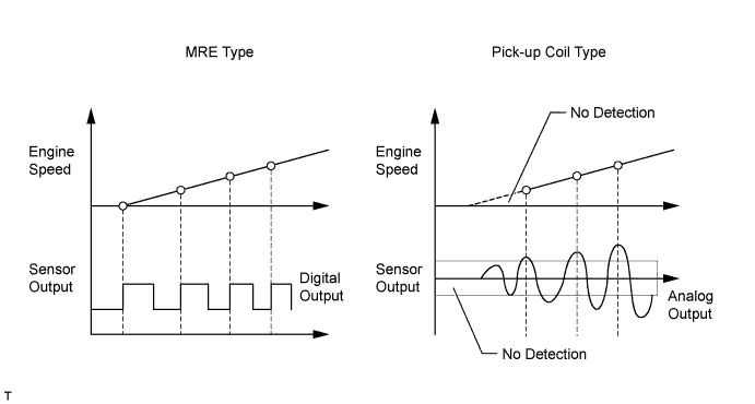
-
-
-
Camshaft Timing Oil Control Valve Assembly
-
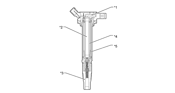
This camshaft timing oil control valve assembly controls the spool valve using duty-cycle control from the ECM. This allows hydraulic pressure to be applied to the VVT-i controller (camshaft timing gear assembly) advance or retard side. When the engine is stopped, the camshaft timing oil control valve assembly will move to the retard position.
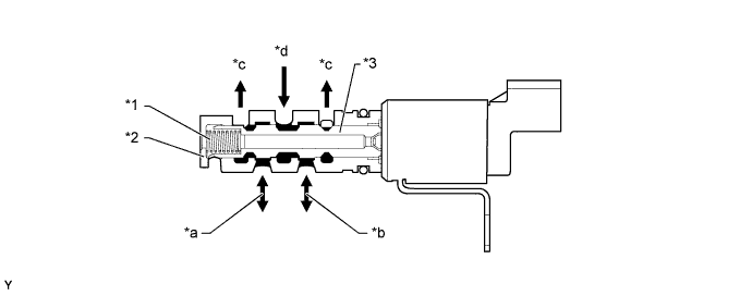
Text in Illustration *1 Spring *2 Sleeve *3 Spool Valve - - *a To Camshaft Timing Gear Assembly
(Advance Side)
*b To Camshaft Timing Gear Assembly
(Retard Side)
*c Drain *d Oil Pressure
-
-
Knock Control Sensor (Flat Type)
-
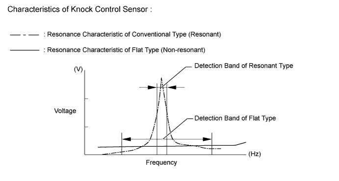
In a conventional knock control sensor (resonant type), a vibration plate is built into the sensor. This plate has the same resonance point as the knocking* frequency of the engine block. This sensor can only detect vibration in this frequency band.
A flat type knock control sensor (non-resonant type) has the ability to detect vibration in a wider frequency band (from about 6 kHz to 15 kHz). It has the following features:
-
A flat type knock control sensor is installed to an engine by placing it over a stud bolt installed on the cylinder block sub-assembly. For this reason, a hole for the stud bolt exists in the center of the sensor.
-
In the sensor, a steel weight is located in the upper portion. An insulator is located between the weight and a piezoelectric element.
-
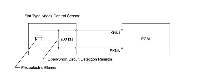
An open/short circuit detection resistor is integrated in the sensor.
*: The term "Knock" or "Knocking" is used in this case to describe either preignition or detonation of the air fuel mixture in the combustion chamber. This preignition or detonation refers to the air fuel mixture being ignited earlier than is advantageous. This use of "Knock" or "Knocking" is not primarily used to refer to a loud mechanical noise that may be produced by an engine.
-
-
The engine knocking frequency will vary slightly depending on the engine speed. A flat type knock control sensor can detect vibration even when the engine knocking frequency changes. Due to the use of a flat type knock control sensor, the vibration detection ability is increased compared to a conventional type knock control sensor, and more precise ignition timing control is possible.
-
Vibrations caused by knocking are transmitted to the steel weight. The inertia of this weight applies pressure to the piezoelectric element. This action generates electromotive force.
-
An open/short circuit detection resistor is integrated in the sensor. When the power switch is on, the open/short circuit detection resistor in the knock control sensor and the resistor in the ECM keep the voltage at terminal KNK1 constant. An Integrated Circuit (IC) in the ECM constantly monitors the voltage of terminal KNK1. If an open/short circuit occurs between the knock control sensor and the ECM, the voltage of terminal KNK1 will change and the ECM will detect the open/short circuit and store a Diagnostic Trouble Code (DTC).
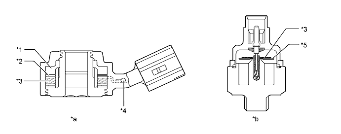
Text in Illustration *1 Steel Weight *2 Insulator *3 Piezoelectric Element *4 Open Circuit Detection Resistor *5 Vibration Plate - - *a Flat Type Knock Control Sensor
(Non-Resonant Type)
*b Conventional Type Knock Control Sensor
(Resonant Type)
-
-
Intake Mass Air Flow Meter Sub-assembly
-
This compact and lightweight plug-in type intake mass air flow meter sub-assembly allows a portion of the intake air to flow through the detection area. By directly measuring the mass and the flow rate of the intake air, the detection precision is improved and the intake air resistance has been reduced.
-
This intake mass air flow meter sub-assembly has a built-in intake air temperature sensor.
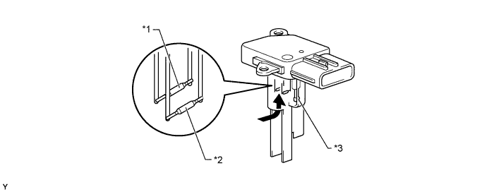
Text in Illustration *1 Platinum Hot-wire Element *2 Temperature Sensing Element *3 Intake Air Temperature Sensor - - 
Air Flow - -
-
-
Throttle Position Sensor
-
This non-contact type throttle position sensor uses a Hall IC, which is mounted on the throttle body assembly.
-
The Hall IC is surrounded by a magnetic yoke (located on the same axis as the throttle shaft). The Hall IC converts the changes that occur in the magnetic flux into electrical signals, and outputs them in the form of throttle valve position signals to the ECM.
-
The Hall IC contains circuits for the main and sub signals. It converts the throttle valve opening angle into electric signals that have differing characteristics, and sends them to the ECM.
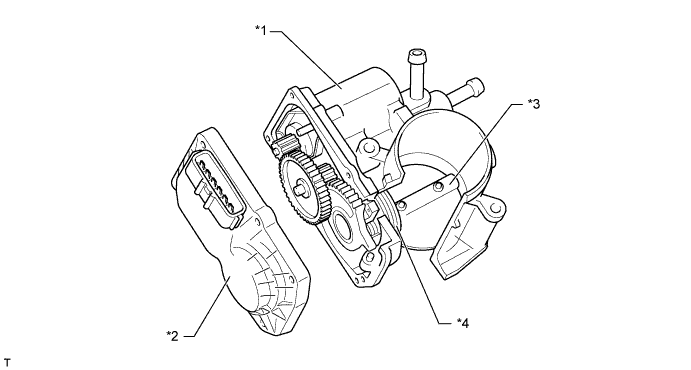
Text in Illustration *1 Throttle Control Motor *2 Throttle Position Sensor *3 Throttle Valve *4 Return Spring 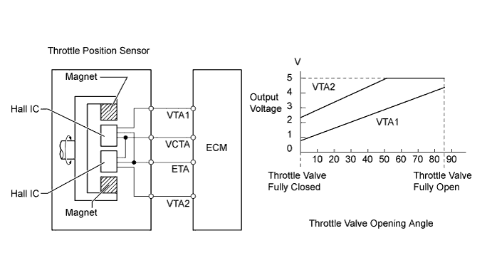
-
-
-
Oxygen Sensor and Air Fuel Ratio Sensor
-
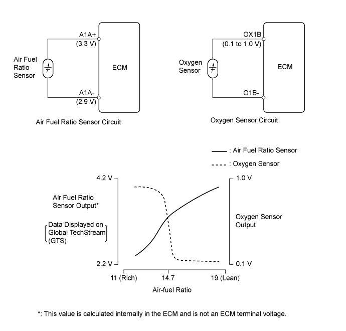
The oxygen sensor and the air fuel ratio sensor differ in output characteristics.
-
The output voltage of the oxygen sensor changes in accordance with the oxygen concentration in the exhaust gas. The ECM uses this output voltage to determine whether the present air-fuel ratio is richer or leaner than the stoichiometric air-fuel ratio.
-
Approximately 3.3 V is constantly applied to the air fuel ratio sensor, which outputs an amperage that varies in accordance with the oxygen concentration in the exhaust gas. The ECM converts the changes in the output amperage into voltage in order to linearly detect the present air-fuel ratio.
-
The basic construction of the oxygen sensor and the air fuel ratio sensor is the same. However, they are divided into the cup type and the planar type, according to the different types of heater construction that are used.
-
The cup type sensor contains a sensor element that surrounds a heater.
-
The planar type sensor uses alumina, which excels in heat conductivity and electrical insulation, to integrate a sensor element with a heater, thus improving the warm up performance of the sensor.
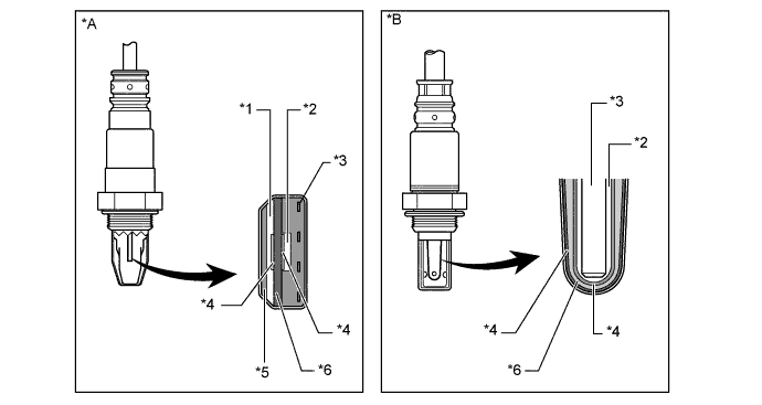
Text in Illustration *A Air Fuel Ratio Sensor
(Planar Type)
*B Oxygen Sensor
(Cup Type)
*1 Diffusion Resistance Layer *2 Atmosphere *3 Heater *4 Platinum Electrode *5 Alumina *6 Sensor Element
(Zirconia)
-
-
Ignition Coil Assembly
-
An igniter is integrated into each ignition coil assembly. There is one ignition coil assembly provided for each cylinder. This improves ignition timing accuracy, reduces high-voltage loss and enhances the overall reliability of the ignition system by eliminating the distributor.
-
The spark plug caps, which provide contact to spark plugs, are integrated into the ignition coil assembly. Also, an igniter is enclosed to simplify the system.
Text in Illustration *1 Igniter *2 Iron Core *3 Spark Plug Cap *4 Secondary Coil *5 Primary Coil - -
-
-
Spark Plug
-
Long-reach, thin-electrode type iridium tipped spark plugs are used. This type of spark plug allows the area of the cylinder head which receives the spark plugs to be made thick. Thus, the water jacket can be extended near the combustion chamber, which contributes to cooling performance.
-
Iridium-tipped spark plugs improve ignition performance while maintaining the same durability as platinum-tipped spark plugs.
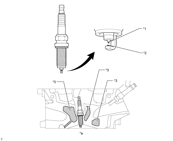
Text in Illustration *1 Iridium Tip *2 Platinum Tip *3 Water Jacket - - *a Cylinder Head Cross Section - -
-
-
-
OPERATION
-
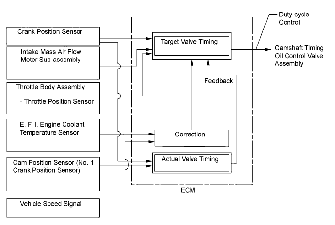
Variable Valve Timing-intelligent (VVT-i) System
-
Based on engine speed, intake air volume, throttle position and engine coolant temperature, the ECM calculates optimal valve timing for all driving conditions. The ECM also controls the camshaft timing oil control valve assembly. In addition, the ECM uses signals from the cam position sensor (No. 1 crank position sensor) and the crank position sensor to detect the actual valve timing, thus providing feedback control to achieve the target valve timing.
-
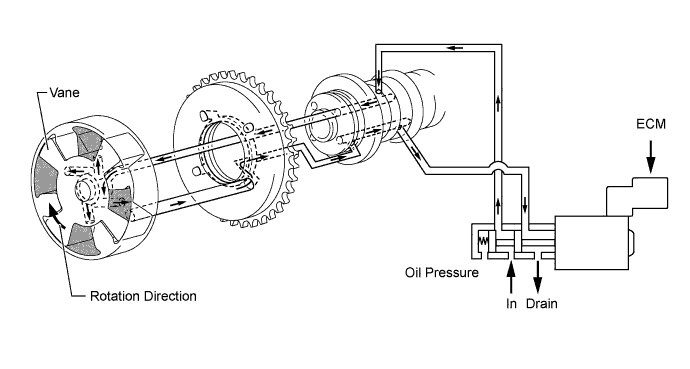
When the camshaft timing oil control valve is operated as illustrated below by the advance signal from the ECM, the resultant oil pressure is applied to the timing advance side vane chamber to rotate the camshaft in the timing advance direction.
-
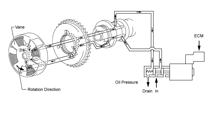
When the camshaft timing oil control valve is operated as illustrated below by the retard signal from the ECM, the resultant oil pressure is applied to the timing retard side vane chamber to rotate the camshaft in the timing retard direction.
-
After reaching the target timing, the valve timing is held by keeping the camshaft timing oil control valve assembly in the neutral position unless the driving conditions change. This maintains the valve timing at the desired target position and prevents the engine oil from running out when it is unnecessary.
-
-
Cooling Fan Control
-
A cooling fan control system in which the ECM controls the cooling fan speed is used. Cooling fan speed is controlled in accordance with the engine coolant temperature, hybrid system coolant temperature and the air conditioning operating conditions.
-
This control is accomplished by operating the 2 fan motors in 2 stages. The fan motors operate in series to achieve low speed, and in parallel to achieve high speed.
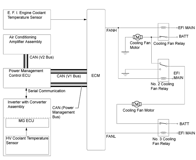
Air Conditioning Operating Condition Engine Coolant Temperature Hybrid System Coolant Temperature Relay Operation Cooling Fan Motor Connection Cooling Fan Operation No. 1 No. 2 No. 3 Off Low Low Off Off Off Off Off High Low On On On Parallel High High High A/C Pressure "Low" Low Low Off Off On Series Low High Low On On On Parallel High High High A/C Pressure "High" High Low On On On Parallel High High High -
If coolant temperature is extremely high and ambient temperature is high when the power switch is turned off, the ECM operates the engine water pump assembly and cooling fan motors for a maximum 3 minutes to ensure engine restartability.
-
-
Water Pump Control
-
Since this engine is stopped and restarted repeatedly by the hybrid system, by providing an electric engine water pump assembly, coolant temperatures while the engine is operating will be stable, and shutting off the power to the pump motor contributes to fuel economy.
-
The ECM receives pump motor speed pulse signals from the electric water pump driver circuit, and then determines the pump motor speed so that an optimal engine coolant flow volume can be obtained according to the operating conditions.
-
-
Fuel Pump Control
-
A fuel cut function is used to stop the fuel pump when any of the SRS airbags have deployed. When the power management control ECU detects the airbag deployment signal from the airbag ECU assembly, it transmits an engine off signal to the ECM. Upon receiving this signal, the ECM turns off the circuit opening relay.
-
After the fuel cut function has been activated, turning the power switch from off to on cancels the fuel cut function, and the engine can be restarted.
-
-
-
FAIL-SAFE
-
When a malfunction of any of the sensors is detected, there is a possibility of an engine or other malfunction occurring if the ECM were to continue normal control. To prevent such a problem, the fail-safe function of the ECM either relies on the data stored in memory to allow the engine control system to continue operating, or stops the engine if a hazard is anticipated. For details, refer to the Repair Manual.
-
-
DIAGNOSIS
-
When the ECM detects a malfunction, the ECM records information related to the fault. Furthermore, the Malfunction Indicator Lamp (MIL) in the combination meter assembly illuminates or blinks to inform the driver.
-
The ECM will also store the Diagnostic Trouble Codes (DTCs) of the malfunctions. The DTCs can be accessed by using the Global TechStream (GTS).
-
For details, refer to the Repair Manual.
-