REAR SUSPENSION SYSTEM GENERAL
-
OUTLINE
-
A torsion-beam type suspension is used.
-
The rear axle carrier bushes are obliquely mounted to obtain a toe-correction function, thus providing excellent driving stability and ride comfort.
-
Through the optimal layout of the suspension, the floor has been made low and flat, providing ample space at the back of the vehicle.
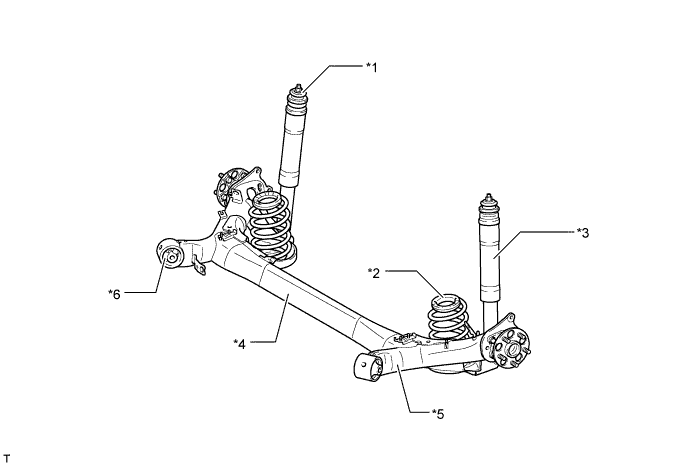
Text in Illustration *1 Rear Suspension Support *2 Rear Coil Spring *3 Rear Shock Absorber Assembly *4 Axle Beam (Rear Axle Beam Assembly) *5 Trailing Arm (Rear Axle Beam Assembly) *6 Rear Axle Carrier Bush Note
Be sure to use the jack-up points that are provided on the body when raising the vehicle with jack. Never apply a jack under the axle beam, spring seats, trailing arm, or bushings of the rear suspension.
-
-
MAIN FEATURES
-
Camber Change
-
In a torsion-beam type suspension, the camber angle and the toe change differ between bound and rebound, offering both straight-line stability and excellent cornering stability.
-
The same as the full-trailing arm type suspension, the axis that joins the center of the right and left bushings in the trailing arms is the center of movement during any same direction travel.
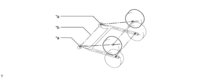
Text in Illustration *a Center of Bushing *b Axis of Movement -
During opposite direction travel, or if any difference in the suspension travel is created between the right and left wheels, the axle beam twists with its shearing center as the center of its rotation. Camber change in relation to the suspension travel is determined by the ratio of the distance between the bushing in the trailing arm, the axle center and the shearing center ("*c" in the figure below) and distance between the bushing in the trailing arm and the axle center ("L" in the figure below). Consequently, through the optimal placement of the axle beam, the changes in the camber angle in relation to the suspension travel have been optimized, thus ensuring excellent cornering performance.
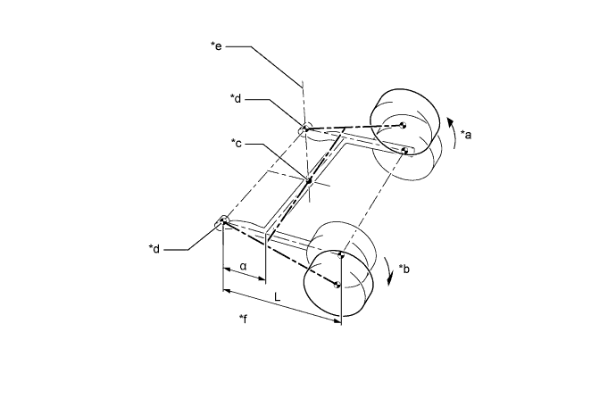
Text in Illustration *a Bound *b Rebound *c Shearing Center *d Center of Bushing *e Instantaneous Rotational Axis of Right Axle *f Camber Change Rate α/L
-
-
Toe-correction Function
-
The longitudinal and lateral forces that are created by the vehicle during cornering cause the bushings in the trailing arms to deform. In a right turn, the right trailing arm moves forward and the left trailing arm moves rearward, creating a tendency for the left wheel to toe-out. In this situation, the bushings that are installed in the trailing arms of a vehicle with a toe-correction function are designed to utilize the lateral force, which is applied to the bushings during cornering, to correct the left trailing arm towards the toe-in direction.
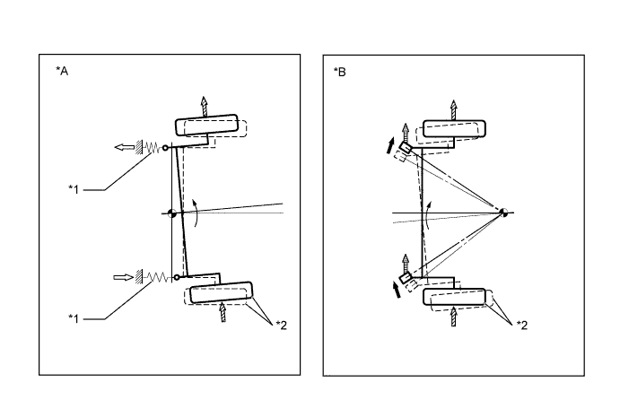
Text in Illustration *A Without Toe-correction Function *B With Toe-correction Function *1 Bushing *2 Left Wheel 
Bushing Movement 
Lateral Force 
Lengthwise Force 
Lateral Force Applied to the Bushing
-
-