AXLE SYSTEM GENERAL
-
OUTLINE
-
Front Axle
-
Compact and highly rigid double-row angular ball bearings are used on the front axle. The double-row angular ball bearings and the axle hub have been integrated to ensure high rigidity, thus offering excellent driving and braking stability.
-
A 12-point lock nut is used for the front axle shaft nut. Secure and solid fastening is achieved by staking the nut. Once removed, this nut cannot be reused.
-
Aluminum steering knuckles are used to achieve weight reduction.
-
Due to an active type speed sensor being adopted, a sensor rotor is provided on the hub bearing inner race.
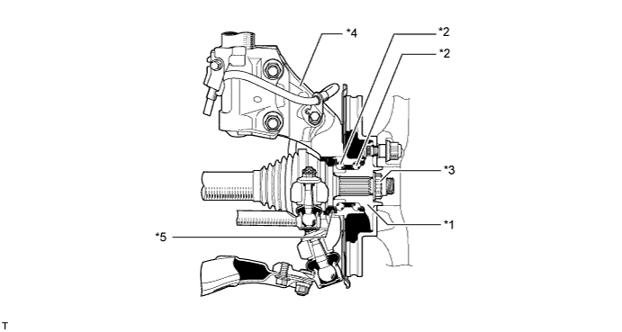
Text in Illustration *1 Front Axle Hub Sub-assembly *2 Double-row Angular Ball Bearing *3 Front Axle Shaft Nut *4 Steering Knuckle *5 Sensor Rotor - - Note
-
Do not place magnetized objects close to the surface of the sensor rotor.
-
Do not allow any iron particles, iron sand, dust, debris or oil to come in contact with the surface of the sensor rotor.
-
-
-
Rear Axle
-
Compact and highly rigid double-row angular ball bearings are used on the rear axle. The double-row angular ball bearings and the axle hub have been integrated to ensure high rigidity, thus achieving excellent driving and braking stability.
-
Due to an active type speed sensor being adopted, a sensor rotor is provided on the hub bearing inner race.
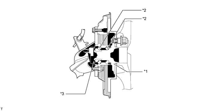
Text in Illustration *1 Rear Axle Hub and Bearing Assembly *2 Double-row Angular Ball Bearing *3 Sensor Rotor - - Note
-
Do not place magnetized objects close to the surface of the sensor rotor.
-
Do not allow any iron particles, iron sand, dust, debris or oil to come in contact with the surface of the sensor rotor.
-
-
-