BODY STRUCTURE DETAILS
-
FUNCTION
-
Impact Absorbing Structure for Frontal Collision
-
A structure that ensures collision energy absorption efficiency, dissipates impact, and minimizes cabin deformation during a frontal collision has been achieved.
-
An engine under brace sub-assembly is used in the lower front portion of the frame. In the event of a frontal collision, the impact energy is transmitted to the frame crossmember sub-assembly No. 1 through the engine under brace sub-assembly. Thus, the moment of the backward rotation at the frame crossmember sub-assembly No. 1 occurs in combination with the moment of the forward rotation at the suspension arm support sub-assembly. This helps minimize the floor deformation caused by the collapse of the suspension arm support sub-assembly.
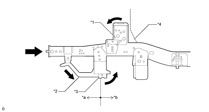
Text in Illustration *1 Suspension Arm Support Sub-assembly *2 Engine Under Brace Sub-assembly *3 Frame Crossmember Sub-assembly No. 1 *4 Floor Panel *a Axial Compression Area *b Moderate Bend Area 
Front Impact Energy - -
-
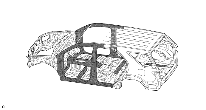
The optimally allocated panels and reinforcements allow the front impact energy received from the front end and frame to be dissipated and absorbed by the front pillar, rocker, and floor reinforcement, in order to minimize the deformation of the cabin.
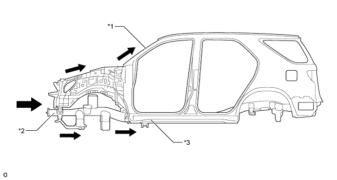
Text in Illustration *1 Front Body Pillar *2 Frame Sub-assembly *3 Rocker - - Front Impact Energy - - -
-
-
Impact Absorbing Structure for Side Collision
-
A structure that ensures collision energy absorption efficiency, dissipates impact, and minimizes cabin deformation during a side collision has been achieved.
-
Impact energy from a side collision directed to the cabin area is dispersed throughout the body via pillar reinforcements, side impact protection beams, and a floor cross member. This dispersion of energy helps keep the energy directed to the cabin at a minimum level.
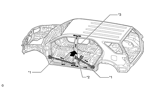
Text in Illustration *1 Side Impact Protection Beam *2 Floor Cross Member *3 Pillar Reinforcement - - Side Impact Energy - -
-
The head impact protection structure is used. With this type of construction, if the occupant's head hits against the roof side rail and pillar in reaction to a collision, the inner ribs of the roof side rail and pillar collapse to help reduce the impact.
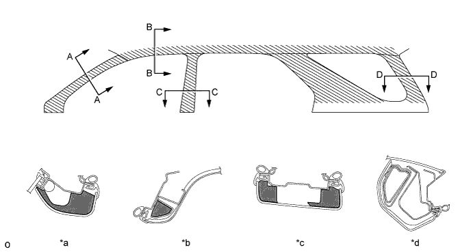
Text in Illustration *a A - A Cross Section *b B - B Cross Section *c C - C Cross Section *d D - D Cross Section 
Head Impact Protection Structure 
Energy Absorbing Rib -
-
-
Aerodynamics
-
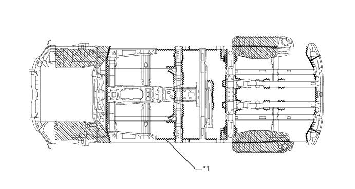
Front wheel opening extension pads are used on the front fender liner to improve the airflow around the front tires.
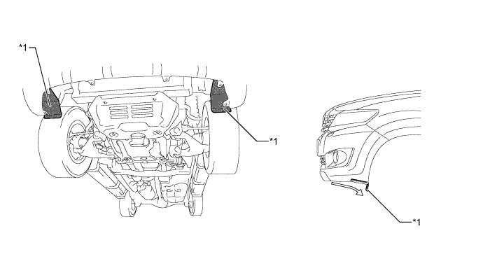
Text in Illustration *1 Front Wheel Opening Extension Pad - - 
Air Flow - -
-
-
-
CONSTRUCTION
-
Lightweight and Highly Rigid Body
-
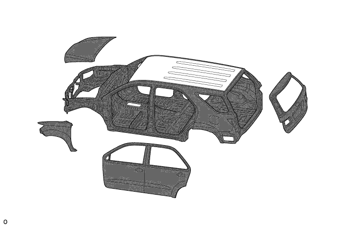
High-tensile strength steel is used in order to achieve excellent body rigidity and a lightweight body.
Text in Illustration High-tensile Strength Steel - - -
A roof panel is used with roof beads and roof reinforcements optimally allocated in order to achieve excellent body rigidity and a lightweight body.
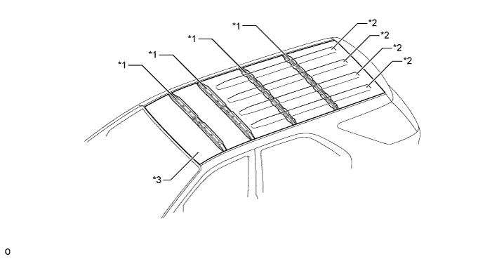
Text in Illustration *1 Roof Reinforcement *2 Roof Bead *3 Roof Panel - -
-
-
Anti-corrosion Sheet Steel
-
Anti-corrosion sheet steel is used as in the following illustration:
Text in Illustration Anti-corrosion Sheet Steel - - -
Wax and sealer are applied to the hemmed portions of the hood panel, door panels, fuel lid, door hinge and back door hinge to improve rust-resistant performance.
-
Polyvinyl Chloride (PVC) coating is applied to the wheel housings, and other parts that are located where they are susceptible to stone chipping damage, improving the rust-resistant performance of these areas.
Text in Illustration *1 Edge Seal - - Under Coating Area - -
-
-
Sound Absorbing and Vibration Damping Materials
-
A dash panel to cowl brace has been provided to connect the dash panel and the top of the floor tunnel in order to minimize the vibration of the dash panel.
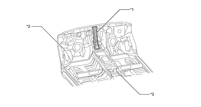
Text in Illustration *1 Dash Panel to Cowl Brace *2 Dash Panel Sub-assembly *3 Floor Tunnel - - -
The areas on which the cab mounts are mounted use spacers to form a box-shaped construction in order to increase rigidity and minimize the transmission of vibration to the body.
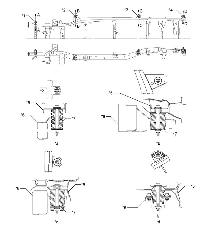
Text in Illustration *1 No. 1 Cab Mount *2 No. 2 Cab Mount *3 No. 3 Cab Mount *4 No. 4 Cab Mount *5 Body Shell *6 Frame Sub-assembly *7 Cab Mounting Cushion Holder - - *a A - A Cross Section *b B - B Cross Section *c C - C Cross Section *d D - D Cross Section -
Asphalt sheets are used to reduce engine and road noise.
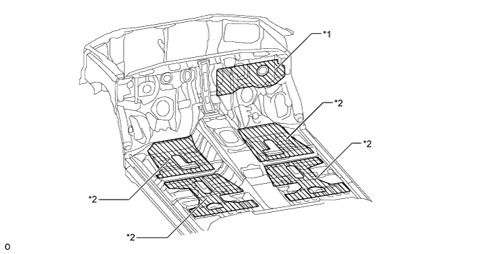
Text in Illustration *1 Asphalt Sheet (Dash Panel Insulator Sheet No. 1) *2 Asphalt Sheet (Front Floor Silencer Sheet) -
A hood insulator is provided on the rear of the hood panel on models with diesel engine. This achieves excellent sound insulation performance.
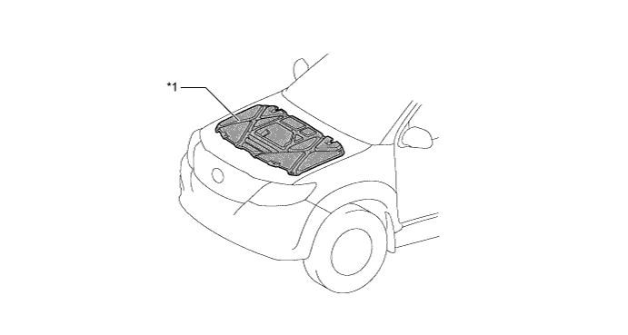
Text in Illustration *1 Hood Insulator - - -
A dash panel insulator outer is provided on models with diesel engine. This reduces the engine noise leaking into and out of the cabin.
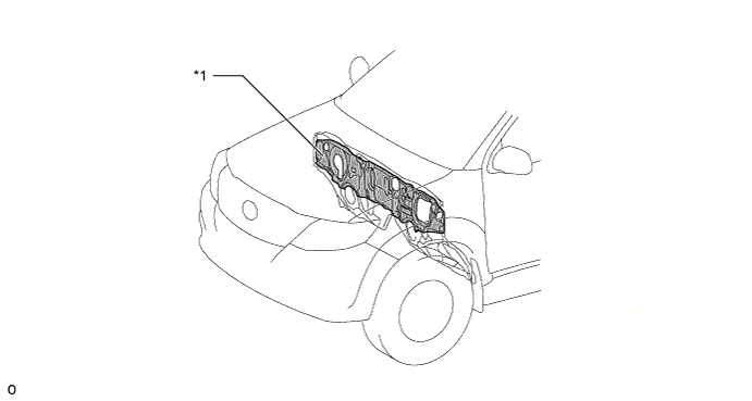
Text in Illustration *1 Dash Panel Insulator Outer - - -
A dash panel insulator is provided. This insulates and absorbs the engine noise to reduce the engine noise leaking into the cabin.
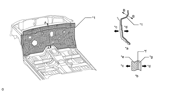
Text in Illustration *1 Dash Panel Insulator - - *a A - A Cross Section *b B - B Cross Section *c Engine Compartment Side *d Cabin Side *e Felt *f Adhesive *g EPDM - - -
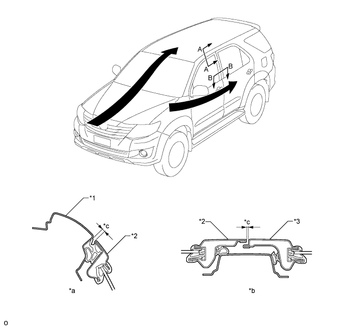
Polyurethane foam is applied to the roof panel and pillars to reduce wind and road noise.
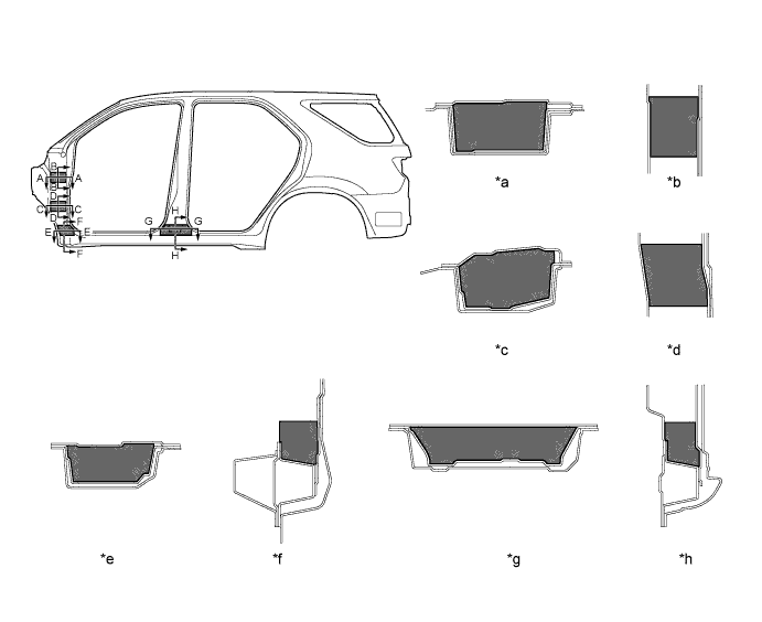
Text in Illustration *a A - A Cross Section *b B - B Cross Section *c C - C Cross Section *d D - D Cross Section *e E - E Cross Section *f F - F Cross Section *g G - G Cross Section *h H - H Cross Section Polyurethane Foam - - -
2 layers of inner weatherstrips and door belt mouldings are used on the front and rear doors to improve sound insulation performance.
-
Door opening trim weatherstrips have been placed along the entire opening of the front and rear doors to ensure stable sound isolation performance.
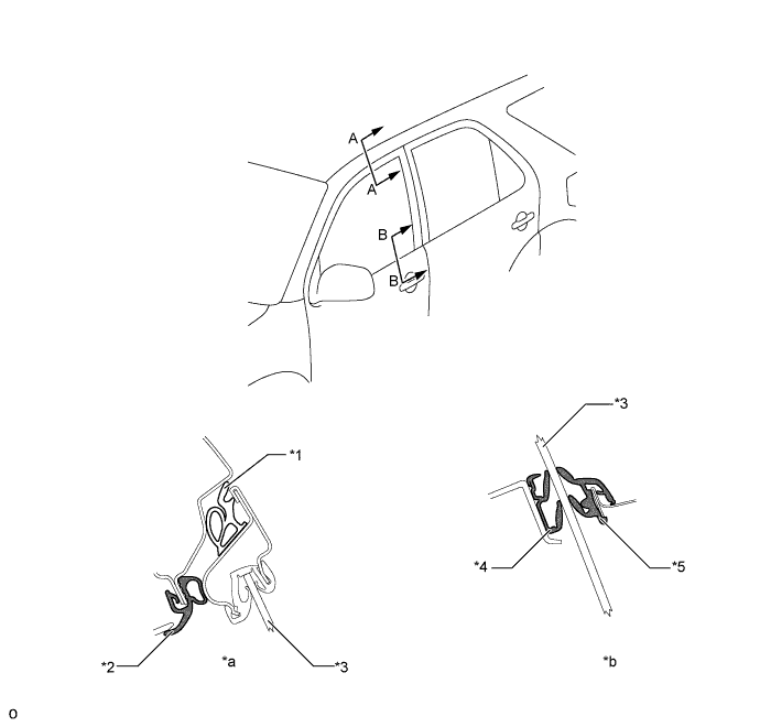
Text in Illustration *1 Door Weatherstrip *2 Door Opening Trim Weatherstrip *3 Door Glass *4 Door Belt Molding *5 Inner Weatherstrip - - *a A - A Cross Section *b B - B Cross Section -
Wind noise has been reduced through the use of the following constructions:
-
The installation angle of the front windshield has been optimized to ensure smooth airflow.
-
The clearance between the door and the door panel has been reduced.
-
The outside rear view mirror has been optimally shaped.
Text in Illustration *1 Side Panel Outer *2 Front Door Outside Panel *3 Rear Door Outside Panel - - *a A - A Cross Section *b B - B Cross Section *c Door Clearance - - -
-
-
Parts with Low Repair Cost
-
The radiator support upper and the hood lock support brace use a bolt-on construction to enable efficient repair or replacement work.
-
A bolt-on type front bumper reinforcement sub-assembly is allocated to join the right and left sides of the front section of the frame sub-assembly, in order to facilitate repairs in case of damage.
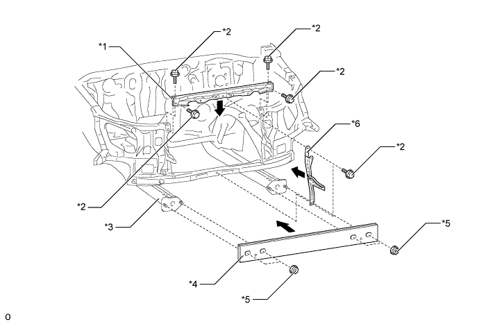
Text in Illustration *1 Radiator Support Upper *2 Bolt *3 Frame Sub-assembly *4 Front Bumper Reinforcement Sub-assembly *5 Nut *6 Hood Lock Support Brace
-
-