BRAKE CONTROL SYSTEM DETAILS
-
FUNCTION OF MAIN COMPONENTS
Component Function Brake Actuator Assembly Changes the fluid path based on the signals from the skid control ECU during the operation of the brake control system functions, in order to control the fluid pressure applied to the wheel cylinders. Motor Relay (Built-into Skid Control ECU) Supplies power to the pump motor. Solenoid Relay (Built-into Skid Control ECU) Supplies power to the solenoid valves. Speed Sensors Detect the wheel speed of each of the 4 wheels. Deceleration Sensor Detects the vehicle's acceleration in forward and reverse. Stop Light Switch Assembly Detects the brake pedal depressing signal. Parking Brake Switch Detects the parking brake lever status. Transfer Indicator Switch (L4 Position)*1 Detects the L4 position condition. Rear Differential Lock Position Switch*2 Detects the rear differential lock actuator operating condition. ABS Warning Light Lights up to alert the driver when the skid control ECU detects a malfunction in the ABS. Skid Control ECU Judges the vehicle driving condition based on the signals from each sensor, and sends the brake control signals to the brake actuator.
-
*1: 4WD models
-
*2: Models with differential lock shift actuator
-
-
SYSTEM CONTROL
-
Anti-lock Brake System (ABS)
-
The ABS prevents the wheels from locking during sudden braking or braking on a slippery surface. This provides the proper braking force when the vehicle slips, thus ensuring vehicle stability and excellent braking performance.
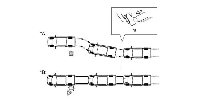
Text in Illustration *A Models with ABS *B Models without ABS *a Brake Operation - -
-
-
-
CONSTRUCTION
-
Brake Actuator Assembly
-
The brake actuator assembly consists of an actuator portion and skid control ECU.
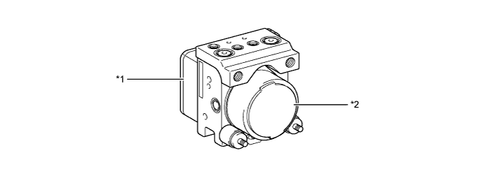
Text in Illustration *1 Skid Control ECU *2 Actuator Portion -
The actuator portion consists of 3 pressure holding solenoid valves, 3 pressure reduction solenoid valves, 2 pumps and 2 reservoirs.
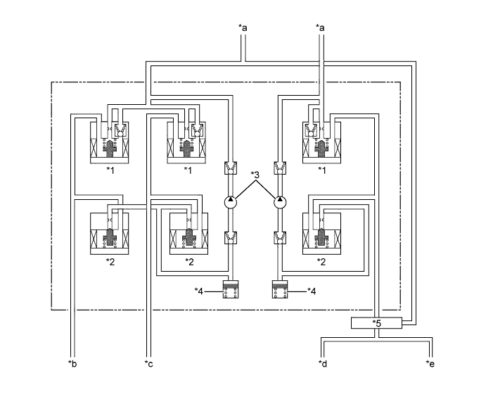
Text in Illustration *1 Pressure Holding Solenoid Valve *2 Pressure Reduction Solenoid Valve *3 Pump *4 Reservoir *5 Brake Control Valve - - *a From Master Cylinder *b Front Brake LH *c Front Brake RH *d Rear Brake LH *e Rear Brake RH - -
-
-
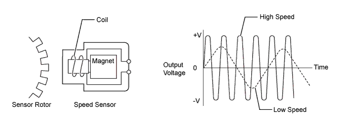
Speed Sensor
-
The speed sensor detects wheel speed and transmits the appropriate signals to the skid control ECU.
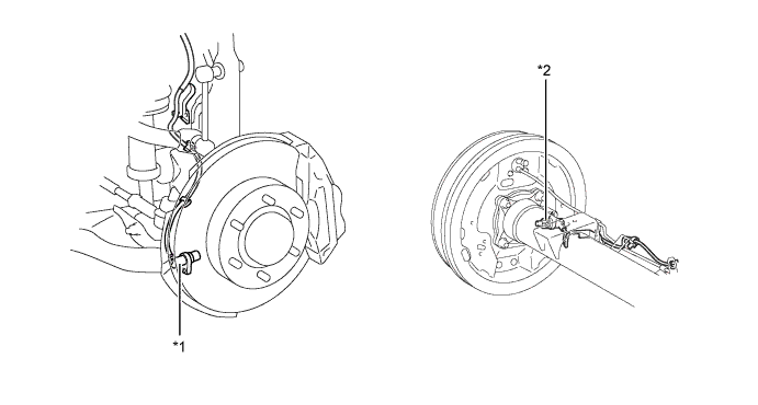
Text in Illustration *1 Front Speed Sensor *2 Rear Speed Sensor -
The pick-up coil type speed sensor is used.
-
-
Deceleration Sensor
-
The deceleration sensor detects the vehicle's acceleration in forward and reverse.
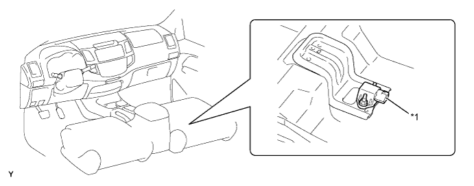
Text in Illustration *1 Deceleration Sensor - -
-
-
-
OPERATION
-
ABS
-
Based on the signals received from the 4 speed sensors and deceleration sensor, the skid control ECU calculates the speed of each wheel and the deceleration, and checks the wheel slipping conditions. In accordance with the slipping condition, the skid control ECU controls each solenoid valve in the brake actuator in order to adjust the fluid pressure of each wheel cylinder in the following 3 modes: pressure increase, pressure holding, and pressure reduction modes.
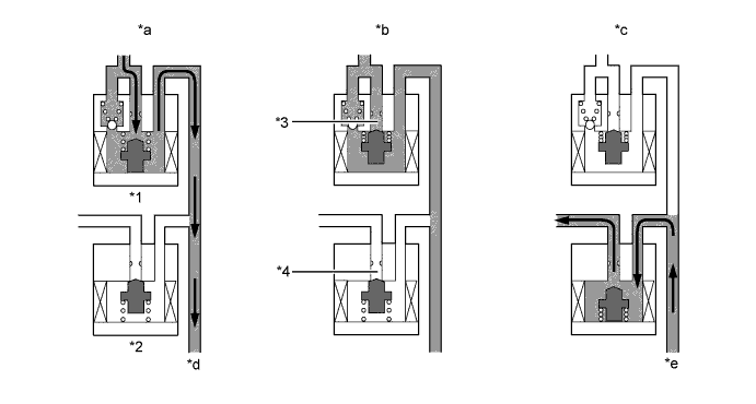
Text in Illustration *1 Pressure Holding Solenoid Valve *2 Pressure Reduction Solenoid Valve *3 Port A *4 Port B *a Pressure Increase Mode *b Pressure Holding Mode *c Pressure Reduction Mode *d To Brake Caliper or Wheel Cylinder *e From Brake Caliper or Wheel Cylinder - - Brake Actuator Operation in ABS Pressure Mode Increase Mode Holding Mode Reduction Mode Pressure Holding Solenoid Valve (Port A) Off (Open) On (Closed) ← Pressure Reduction Solenoid Valve (Port B) Off (Closed) ← On (Open) Wheel Cylinder Pressure Increases Holds Reduces
-
-
-
FAIL-SAFE
-
If a failure occurs in the skid control ECU, sensors, or brake actuator, the system continues effecting brake control by excluding the failed area and using only the areas that are operating normally.
-
-
DIAGNOSIS
-
If the skid control ECU detects a malfunction in the brake control system, the warning lights or indicator light illuminate. At the same time, a Diagnostic Trouble Code (DTC) is stored in the memory of the skid control ECU.
-
This system has a sensor signal check (test mode) function.
-
For details of DTC and check function, refer to the corresponding Repair Manual for this model.
-