SFI SYSTEM DETAILS
-
FUNCTION OF MAIN COMPONENTS
-
The main components of the engine control system are as follows:
Component Outline Quantity Function ECM 32-bit CPU 1 The ECM optimally controls the SFI, ESA and ISC to suit the operating conditions of the engine in accordance with the signals provided by the sensors. Intake Mass Air Flow Meter Sub-assembly Hot-wire Type 1 This sensor has a built-in hot-wire to directly detect the intake air mass. Intake Air Temperature Sensor Thermistor Type 1 This sensor detects the intake air temperature by means of an internal thermistor. Engine Coolant Temperature Sensor Thermistor Type 1 This sensor detects the engine coolant temperature by means of an internal thermistor. Crankshaft Position Sensor [Rotor Teeth] Pick-up Coil Type [36 - 2] 1 This sensor detects the engine speed and performs cylinder identification. Camshaft Position Sensor [Rotor Teeth] Magnetic Resistance Element (MRE) Type [3] 2 (1 each bank) This sensor performs cylinder identification. Accelerator Pedal Position Sensor Linear (Non-contact) Type 1 This sensor detects the amount of pedal effort applied to the accelerator pedal. Throttle Position Sensor Linear (Non-contact) Type 1 This sensor detects the throttle valve opening angle. Knock Control Sensor (Bank 1 and Bank 2) Built-in Piezoelectric Type (Non-resonant Type/Flat Type) 2 (1 each bank) This sensor detects an occurrence of engine knocking indirectly from the vibration of the cylinder block caused by the occurrence of engine knocking. Air Fuel Ratio Sensor (Bank 1, Sensor 1) (Bank 2, Sensor 1) Heated Type (Planar Type) 2 (1 each bank) As with the oxygen sensor, this sensor detects the oxygen concentration in the exhaust emission. However, it detects the oxygen concentration in the exhaust emission linearly. Oxygen Sensor (Bank 1, Sensor 2) (Bank 2, Sensor 2) Heated Type (Cup Type) 2 (1 each bank) This sensor detects the oxygen concentration in the exhaust emission by measuring the electromotive force which is generated in the sensor itself. Fuel Injector Assembly 12-hole Type 6 The fuel injector assembly is an electromagnetically-operated nozzle which injects fuel in accordance with signals from the ECM.
-
-
SYSTEM CONTROL
-
The engine control system has the following features. The ECM controls these systems:
System Outline Sequential Multiport Fuel Injection (SFI)
-
An L-type SFI system directly detects the intake air mass with a hot-wire type mass air flow meter.
-
The fuel injection system is a sequential multiport fuel injection system.
Electronic Spark Advance (ESA)
-
Ignition timing is determined by the ECM based on signals from various sensors. The ECM corrects ignition timing in response to engine knocking.
-
This system selects the optimal ignition timing in accordance with the signals received from the sensors and sends (IGT) ignition signals to the igniters.
Electronic Throttle Control System-intelligent (ETCS-i) Optimally controls the throttle valve opening in accordance with the amount of accelerator pedal effort, the throttle valve opening control request from the ECM, and the condition of the engine and the vehicle. Variable Valve Timing-intelligent (VVT-i) Regulates operation of the intake camshafts to ensure an optimal valve timing in accordance with the engine condition. Fuel Pump Control
-
Fuel pump speed is controlled by the fuel pump relay and the fuel pump resistor.
-
The fuel pump is stopped when the Supplemental Restraint System (SRS) airbags are deployed.
Air Conditioning Cut-off Control By turning the air conditioning compressor assembly on or off in accordance with the engine condition, driveability is maintained. Air Fuel Ratio Sensor and Oxygen Sensor Heater Control Maintains the temperature of the air fuel ratio sensors or oxygen sensors at an appropriate level to increase the detection accuracy of the exhaust gas oxygen concentration. Engine Immobiliser Prohibits fuel delivery and ignition if an attempt is made to start the engine with an invalid key. Diagnosis When the ECM detects a malfunction, the ECM diagnoses and memorizes the failed section. Fail-safe When the ECM detects a malfunction, the ECM stops or controls the engine in accordance with the data already stored in memory. -
-
-
FUNCTION
-
VVT-i System
-
The VVT-i system is designed to control the intake camshaft within a range of 50° (of crankshaft angle) to provide valve timing that is optimally suited to the engine operating conditions. This improves torque in all the speed ranges as well as increasing fuel economy and reducing exhaust emissions.
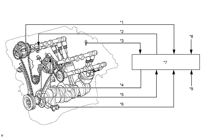
Text in Illustration *1 Camshaft Position Sensor (Bank 1) *2 Camshaft Timing Oil Control Valve Assembly (Bank 1) *3 Engine Coolant Temperature Sensor *4 Camshaft Timing Oil Control Valve Assembly (Bank 2) *5 Camshaft Position Sensor (Bank 2) *6 Crankshaft Position Sensor *7 ECM *8 Accelerator Pedal Position Sensor *9 Throttle Position Sensor - - 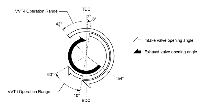
-
The VVT-i system delivers excellent benefits in the different operating conditions as shown in the table below:
Operation State Objective Effect During Idling 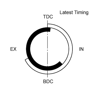
Eliminating overlap reduces blow back to the intake side.
-
Stabilized idling speed
-
Better fuel economy
At Light Load 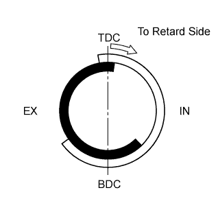
Decreasing overlap to reduce blow back to the intake side. Ensured engine stability At Medium Load 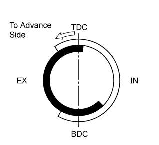
Increasing overlap to increase internal EGR to reduce pumping loss.
-
Better fuel economy
-
Improved emission control
In Low to Medium Speed Range with Heavy Load 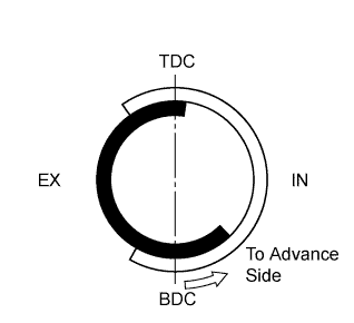
Advancing the intake valve close timing for volumetric efficiency improvement. Improved torque in low to medium speed range In High Speed Range with Heavy Load 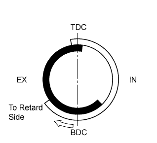
Retarding the intake valve close timing for volumetric efficiency improvement. Improved output At Low Temperatures Eliminating overlap to prevent blow back to the intake side leads to the lean burning condition, and stabilizes the idling speed at fast idle.
-
Stabilized fast idle speed
-
Better fuel economy
-
Starting Engine
-
Stopping Engine
Eliminating overlap to minimize blow back to the intake side. Improved startability -
-
-
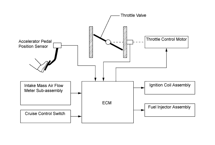
Electronic Throttle Control System-intelligent (ETCS-i)
-
The ETCS-i is used, providing excellent throttle control in all the operating ranges. The accelerator cable has been discontinued, and an accelerator pedal position sensor has been provided on the accelerator pedal.
-
In the conventional throttle body, the throttle valve opening is determined by the amount of the accelerator pedal effort. In contrast, the ETCS-i uses the ECM to calculate the optimal throttle valve opening that is appropriate for the respective driving condition and uses a throttle control motor to control the opening.
-
The ETCS-i controls the idle speed and cruise control system.
-
In case of an abnormal condition, this system switches to the limp mode.
-
-
Acoustic Control Induction System (ACIS)
-
The ACIS uses a bulkhead to divide the intake manifold into two stages, with an intake air control valve in the bulkhead being opened and closed to vary the effective length of the intake manifold in accordance with the engine speed and throttle valve opening angle. This increases the power output in all ranges from low to high speed.
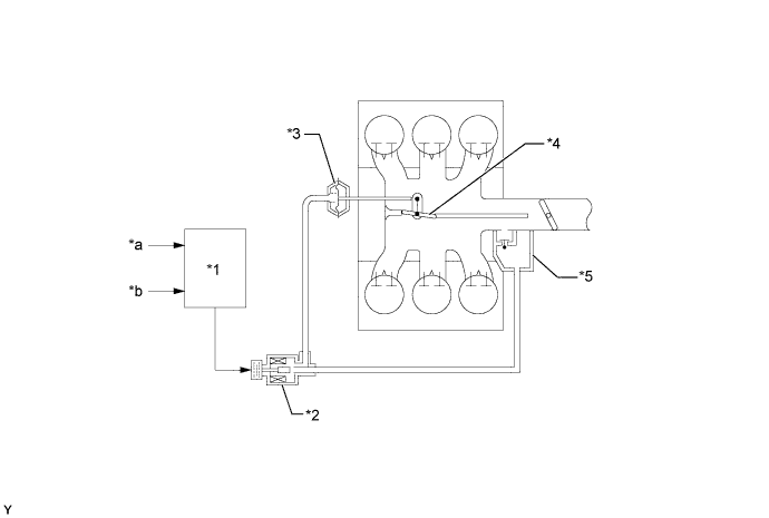
Text in Illustration *1 ECM *2 VSV (for ACIS) *3 Actuator *4 Intake Air Control Valve *5 Vacuum Tank - - *a Engine Speed *b Throttle Opening Angle
-
-
Fuel Pump Control
-
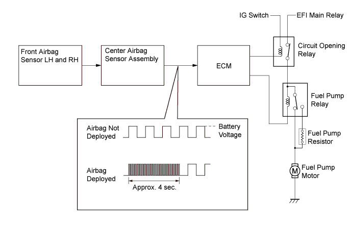
The fuel pump is controlled by the ECM, using the circuit opening relay, fuel pump relay and the fuel pump resister.
-
The fuel pump control has a fuel cut control. The fuel cut control stops the fuel pump when any of the Supplemental Restraint System (SRS) airbags have deployed.
-
-
-
CONSTRUCTION
-
Air Fuel Ratio Sensor and Oxygen Sensor
-
A planar type air fuel ratio sensor and a cup type oxygen sensor are used. The basic construction of the oxygen sensor and the air fuel ratio sensor is the same. However, they are divided into the cup type and the planar type, in accordance with the different types of heater construction used.
-
The planar type air fuel ratio sensor uses alumina, which excels in heat conductivity and electrical insulation, to integrate the sensor element with a heater, thus improving the warmup performance of the sensor.
-
The cup type oxygen sensor contains a sensor element that surrounds the heater.
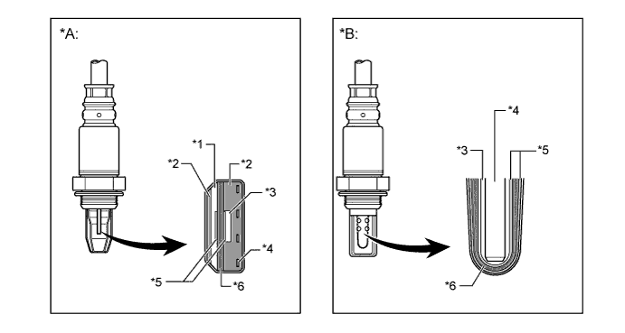
Text in Illustration *A Planar Type Air Fuel Ratio Sensor *B Cup Type Oxygen Sensor *1 Diffusion Resistance Layer *2 Alumina *3 Atmosphere *4 Heater *5 Platinum Electrode *6 Sensor Element (Zirconia) -
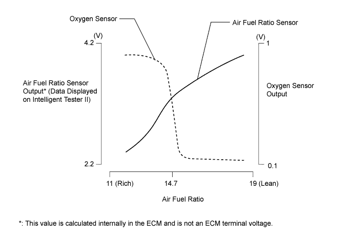
As illustrated below, the conventional oxygen sensor is characterized by a sudden change in its output voltage at the threshold of the stoichiometric air fuel ratio (14.7:1). In contrast, the air fuel ratio sensor data is approximately proportionate to the existing air fuel ratio. The air fuel ratio sensor converts the oxygen density to current and sends it to the ECM. As a result, the detection precision of the air fuel ratio has been improved. The air fuel ratio sensor data can be viewed using an intelligent tester II.
-
-
Intake Mass Air Flow Meter Sub-assembly
-
This engine uses the hot-wire type air flow meter designed for direct electrical measurement of the intake air mass flow.
-
This intake mass air flow meter sub-assembly has a built-in intake air temperature sensor.
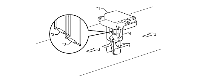
Text in Illustration *1 Intake Mass Air Flow Meter Sub-assembly *2 Temperature Sensing Element *3 Platinum Hot-wire Element *4 Intake Air Temperature Sensor 
Air Flow - -
-
-
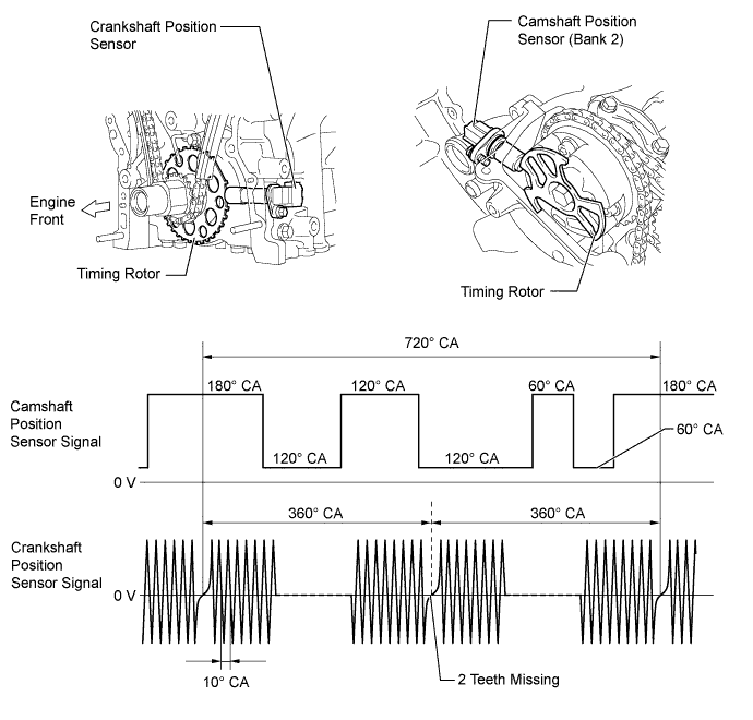
Crankshaft Position Sensor and Camshaft Position Sensor
-
A pick-up coil type crankshaft position sensor is used. The timing rotor of the crankshaft consists of 34 teeth, with 2 teeth missing. The crankshaft position sensor outputs the crankshaft rotation signals every 10°, and the missing teeth are used to determine the top-dead-center.
-
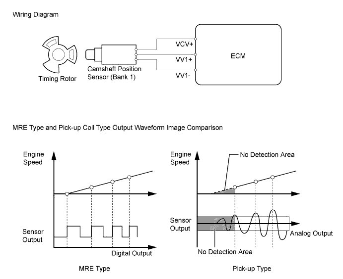
A Magnetic Resistance Element (MRE) type camshaft position sensor is used. To detect the camshaft position, a timing rotor that is secured to the camshaft in front of the VVT controller is used to generate 6 (3 high output, 3 low output) pulses for every 2 revolutions of the crankshaft.
-
The MRE type camshaft position sensor consists of an MRE, a magnet and a sensor. The direction of the magnetic field changes due to the different shapes (protruded and non-protruded portions) of the timing rotor, which passes by the sensor. As a result, the resistance of the MRE changes, and the output voltage to the ECM changes to high or low. The ECM detects the camshaft position based on this output voltage.
-
-
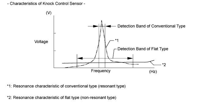
Knock Control Sensor (Flat Type)
-
In a conventional type knock control sensor (resonant type), a vibration plate is built into the sensor. This plate has the same resonance point as the knocking* frequency of the engine block. This sensor can only detect vibration in this frequency band.
-
*: The term "knock" or "knocking" is used in this case to describe either preignition or detonation of the air fuel mixture in the combustion chamber. This preignition or detonation refers to the air fuel mixture being ignited earlier than is advantageous. This use of "knock" or "knocking" is not primarily used to refer to a loud mechanical noise that may be produced by an engine.
-
-
A flat type knock control sensor (non-resonant type) has the ability to detect vibration in a wider frequency band (from approximately 6 kHz to 15 kHz). It has the following features:
-
The engine knocking frequency will vary slightly depending on the engine speed. The flat type knock control sensor can detect vibration even when the engine knocking frequency changes. Due to the use of the flat type knock control sensor, the vibration detection ability has been increased compared to a conventional type knock control sensor, and more precise ignition timing control is possible.
-
-
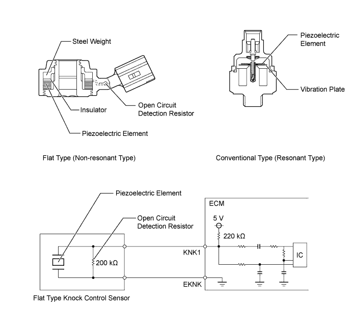
A flat type knock control sensor is installed in an engine by placing it over the stud bolt installed on the cylinder block. For this reason, a hole for the stud bolt exists in the center of the sensor.
-
In the sensor, a steel weight is located in the upper portion. An insulator is located between the weight and the piezoelectric element.
-
An open/short circuit detection resistor is integrated in the sensor. When the ignition switch is ON, the open/short circuit detection resistor in the knock control sensor and the resistor in the ECM keep the voltage at terminal KNK1 constant. An Integrated Circuit (IC) in the ECM constantly monitors the voltage of terminal KNK1. If the open/short circuit occurs between the knock control sensor and the ECM, the voltage of terminal KNK1 will change and the ECM will detect the open/short circuit and store a Diagnostic Trouble Code (DTC).
-
Vibrations caused by knocking are transmitted to the steel weight. The inertia of this weight applies pressure to the piezoelectric element. This action generates electromotive force.

Text in Illustration *1 Steel Weight *2 Piezoelectric Element 
Inertia - - -
These knock control sensors are mounted in the specific directions and angles as illustrated. To prevent the right and left bank connectors from being interchanged, make sure to install each sensor in its prescribed direction.
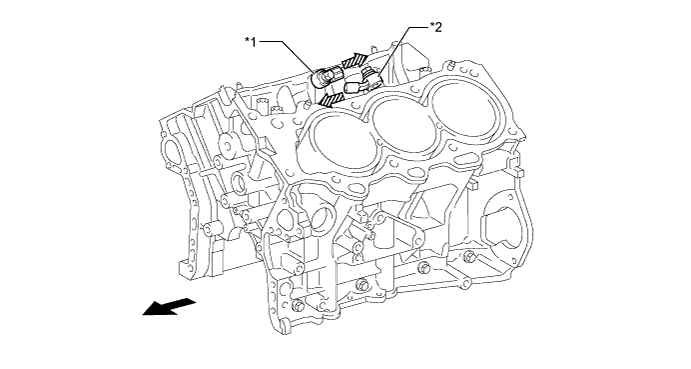
Text in Illustration *1 Knock Control Sensor (Bank 1) *2 Knock Control Sensor (Bank 2) Engine Front 
Knock Control Sensor Mounting Direction
-
-
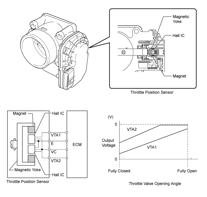
Throttle Position Sensor
-
A non-contact type throttle position sensor is used. This sensor uses a Hall IC, which is mounted on the throttle body.
-
The Hall IC is surrounded by a magnetic yoke. The Hall IC converts the changes that occur in the magnetic flux into electrical signals and outputs them as throttle valve effort to the ECM.
-
The Hall IC contains circuits for the main and sub signals. It converts the throttle valve opening angles into electric signals with two differing characteristics and outputs them to the ECM.
-
-
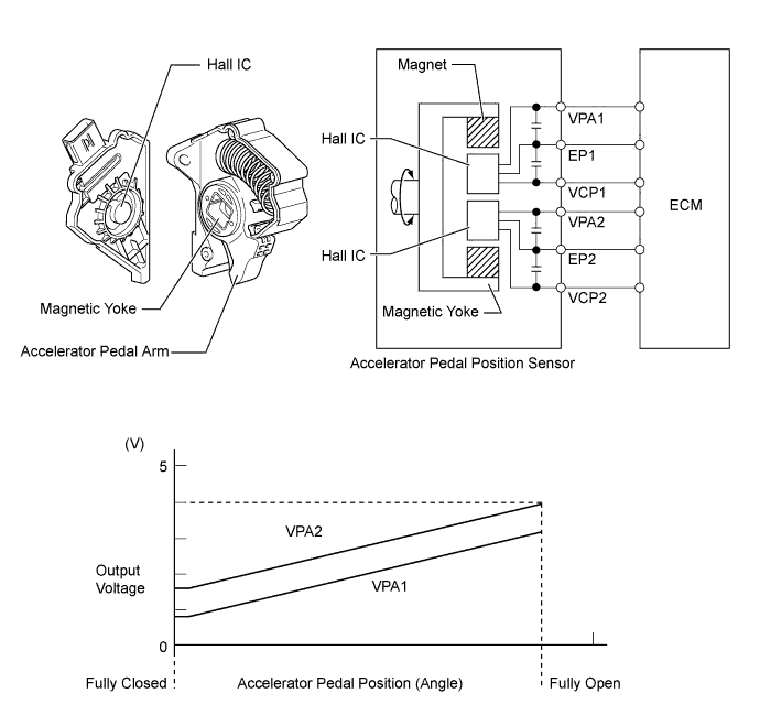
Accelerator Pedal Position Sensor
-
This non-contact type accelerator pedal position sensor uses a Hall IC, which is mounted on the accelerator pedal arm.
-
A magnetic yoke is mounted at the base of the accelerator pedal arm. This yoke rotates around the Hall IC in accordance with the amount of effort that is applied to the accelerator pedal. The Hall IC converts the changes in the magnetic flux that occur into electrical signals, and outputs them in the form of accelerator pedal position signals to the ECM.
-
This accelerator pedal position sensor includes 2 Hall ICs and circuits for the main and sub signals. It converts the accelerator pedal depressed angles into electric signals with two differing characteristics and outputs them to the ECM.
-
-
Camshaft Timing Oil Control Valve Assembly
-
This camshaft timing oil control valve assembly controls the spool valve using duty cycle control from the ECM. This allows hydraulic pressure to be applied to the VVT-i controller advanced or retarded side. When the engine is stopped, the camshaft timing oil control valve assembly is in the most retarded position.
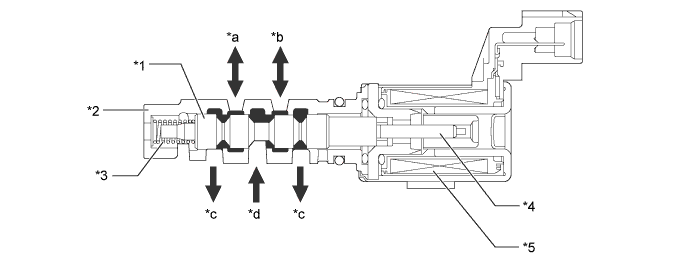
Text in Illustration *1 Spool Valve *2 Sleeve *3 Spring *4 Plunger *5 Coil - - *a To VVT-i Controller (Advance Side) *b To VVT-i Controller (Retard Side) *c Drain *d Oil Pressure
-
-
Throttle Control Motor
-
A DC motor with excellent response and minimal power consumption is used for the throttle control motor. The ECM performs the duty cycle control of the direction and the amperage of the current that flows to the throttle control motor in order to regulate the opening of the throttle valve.
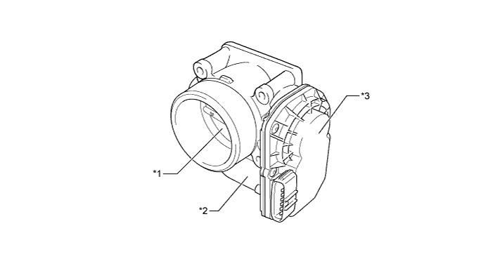
Text in Illustration *1 Throttle Valve *2 Throttle Control Motor *3 Throttle Position Sensor Portion - -
-
-
Ignition Coil Assembly
-
The Direct Ignition System (DIS) provides 6 ignition coil assemblies, one for each cylinder. The spark plug caps, which provide contact to spark plugs, are integrated with the ignition coil. Also, an igniter is enclosed to simplify the system.
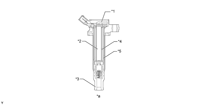
Text in Illustration *1 Igniter *2 Iron Core *3 Plug Cap *4 Secondary Coil *5 Primary Coil - - *a Ignition Coil Cross Section - -
-
-
Spark Plug
-
Long-reach type spark plugs are used. This type of spark plug allows the area of the cylinder head that receives the spark plugs to be made thick. Thus, the water jacket can be extended near the combustion chamber, which contributes to cooling performance.
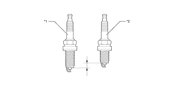
Text in Illustration *1 Long-reach Type Spark Plug *2 Conventional Type Spark Plug
-
-
-
OPERATION
-
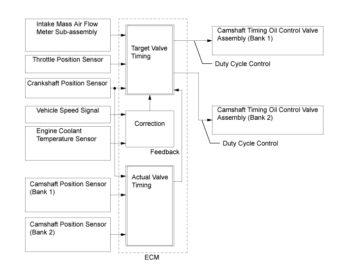
VVT-i System
-
Using the engine speed, intake air mass, throttle position and engine coolant temperature, the ECM can calculate optimal valve timing for each driving condition and controls the camshaft timing oil control valve assembly. In addition, the ECM uses signals from the camshaft position sensor and the crankshaft position sensor to detect the actual valve timing, thus providing feedback control to achieve the target valve timing.
-
When the camshaft timing oil control valve assembly is positioned as illustrated below by the advance signals from the ECM, the resultant oil pressure is applied to the timing advance side vane chamber to rotate the camshaft in the timing advance direction:
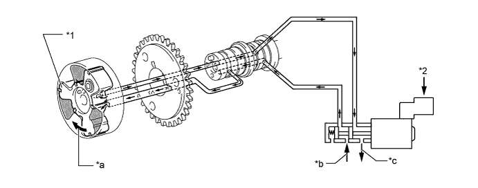
Text in Illustration (Advance Side Operation) *1 Vane *2 ECM *a Rotation Direction *b In (Oil Pressure) *c Drain (Oil Pressure) - - -
When the camshaft timing oil control valve assembly is positioned as illustrated below by the retard signals from the ECM, the resultant oil pressure is applied to the timing retard side vane chamber to rotate the camshaft in the timing retard direction:
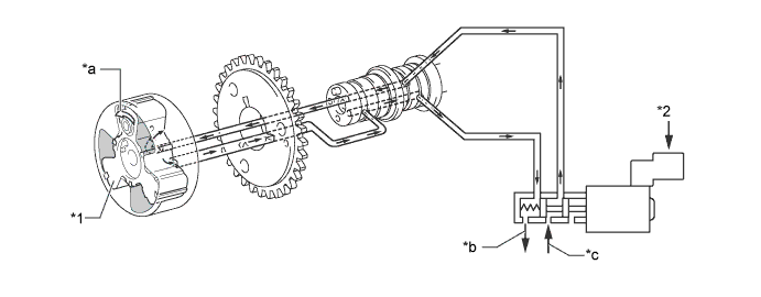
Text in Illustration (Retard Side Operation) *1 Vane *2 ECM *a Rotation Direction *b Drain (Oil Pressure) *c In (Oil Pressure) - - -
After reaching the target timing, the valve timing is held by keeping the camshaft timing oil control valve assembly in the neutral position unless the traveling state changes. This adjusts the valve timing at the desired target position and prevents the engine oil from running out when it is unnecessary.
-
-
ACIS
-
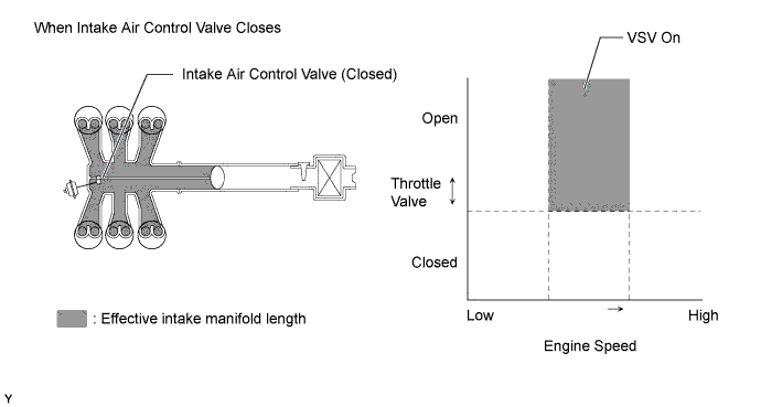
When Intake Control Valve Closes (VSV On)
-
The ECM activates the VSV to match the longer pulsation cycle so that the negative pressure acts on the diaphragm chamber of the actuator. This closes the control valve. As a result, the effective length of the intake manifold is lengthened and the intake efficiency in the medium speed range is improved due to the dynamic effect of the intake air, thereby increasing the power output.
-
-
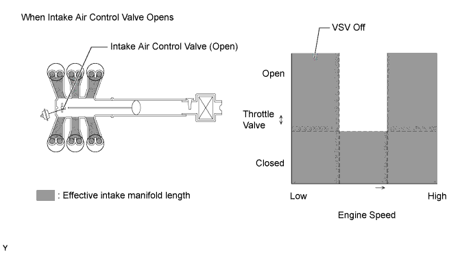
When the Intake Control Valve Opens (VSV Off)
-
The ECM deactivates the VSV to match the shorter pulsation cycle so that atmospheric air is led into the diaphragm chamber of the actuator and opens the control valve. When the control valve is open, the effective length of the intake air chamber is shortened and peak intake efficiency is shifted to the low-to-high engine speed range, thus providing greater output at low-to-high engine speeds.
-
-
-
Fuel Pump Control
-
Fuel pump speed is controlled by the ECM, using the fuel pump relay and the fuel pump resistor.
-
When the ECM detects the airbag deployment signal from the center airbag sensor assembly, the ECM will turn the circuit opening relay off. After the fuel cut control has been activated, turning the ignition switch from off to the ON cancels the fuel cut control, and the engine can be restarted.
-
-
ETCS-i
-
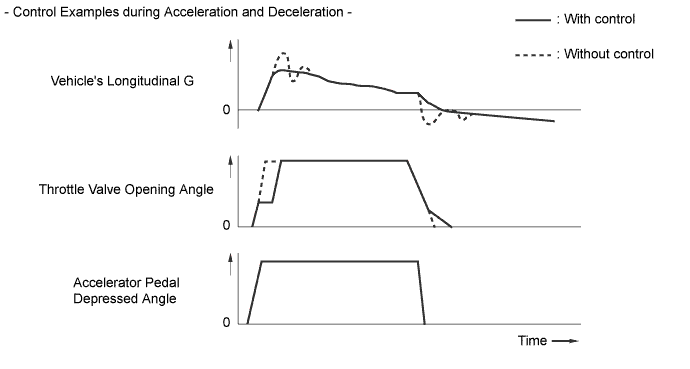
The ECM drives the throttle control motor by determining the target throttle valve opening in accordance with the respective operating condition.
-
The ECM controls the throttle to an optimal throttle valve opening that is appropriate for the driving conditions such as the amount of accelerator pedal effort and the engine speed in order to achieve excellent throttle control and comfort in all operating ranges.
-
The ECM controls the throttle valve in order to constantly maintain an ideal idle speed.
-
The ECM directly actuates the throttle valve for operation of the cruise control.
-
-