AIR CONDITIONING SYSTEM
-
FUNCTION OF MAIN COMPONENTS
-
The air conditioning system consists of the following parts:
Component Function Air Conditioning Control Assembly Allows operation and adjustment of the air conditioning system via switches. Air Conditioning Amplifier Assembly Transmits and receives data between the switches and sensors. Electric Inverter Compressor (Compressor with Motor Assembly) Performs suction, compression and discharge of refrigerant gas and is driven by the electric motor. Blower Motor with Fan Sub-assembly High magnetic force magnets and ball bearings are used to achieve a compact and lightweight assembly. Cooler Condenser Assembly A Global Inner-fin condenser is used to improve heat exchange efficiency. Heater Radiator Unit Sub-assembly A Straight Flow Aluminum (SFA)-II heater radiator is used for compactness and high performance. No. 1 Cooler Evaporator Sub-assembly A Revolutionary super-Slim structure (RS) evaporator is used for compactness. Evaporator Temperature Sensor (No. 1 Cooler Thermistor) Detects the temperature of the fin surface of the No. 1 cooler evaporator sub-assembly and transmits the data to the air conditioning amplifier assembly. Ambient Temperature Sensor (Thermistor Assembly) Detects ambient temperature and outputs it to the air conditioning amplifier assembly. Cooler Thermistor (Room Temperature Sensor) Detects room temperature and outputs it to the air conditioning amplifier assembly. Automatic Light Control Sensor*1 / Cooler Thermistor (Solar Sensor)*2 Detects the changes in the amount of solar energy and outputs them to the air conditioning amplifier assembly. PTC Heater (Quick Heater Assembly)*3 Generates heat according to the Positive Temperature Coefficient (PTC) heater control signal. Air Mix Servo Motor (No. 1 Air Conditioning Radiator Damper Servo Sub-assembly, No. 3 Air Conditioning Radiator Damper Servo Sub-assembly) Receives the input of temperature setting signals via the air conditioning amplifier assembly, operates the motor and opens and closes the air mix damper. Air Inlet Servo Motor (No. 1 Blower Damper Servo Sub-assembly) Receives the input of the operation signals from the fresh-air/recirculation selector switch via the air conditioning amplifier assembly, operates the motor and opens and closes the fresh-air/recirculation damper. Air Outlet Servo Motor (No. 2 Air Conditioning Radiator Damper Servo Sub-assembly) Receives the input of the operation signals from the mode selector switch via the air conditioning amplifier assembly, operates the motor and opens and closes the mode damper. Clean Air Filter Removes pollen and other particles to provide a comfortable interior space. Air Conditioner Pressure Sensor Detects the refrigerant pressure and sends the data to the air conditioning amplifier assembly. Hybrid Vehicle Control ECU Controls the electric inverter compressor (compressor with motor assembly). ECM Receives the signals from the E.F.I. engine coolant temperature sensor and transmits them to the air conditioning amplifier assembly. Combination Meter Assembly Transmits the vehicle speed signal to the air conditioning amplifier assembly. Inverter with Converter Assembly Transmits the power control unit state signal to the air conditioning amplifier assembly. ECO MODE Switch (Eco Switch Assembly) Sends the ECO MODE switch operation signal to the air conditioning amplifier assembly. Seat Heater Switch*4 Sends the seat heater switch operation signal to the air conditioning amplifier assembly.
-
*1: Models with automatic light control system
-
*2: Models without automatic light control system
-
*3: Cold area specification models
-
*4: Models with seat heater system
-
-
-
SYSTEM CONTROL
-
Control List
-
The air conditioning system uses the following types of control.
Control Outline Neural Network Control This control is capable of effecting complex control by artificially simulating the information processing method of the nervous system of living organisms in order to establish a complex input or output relationship that is similar to a human brain. Outlet Air Temperature Control In compliance with the temperature set at the temperature control switch, the neural network control calculates the outlet temperature based on the input signals from various sensors. In addition, corrections in accordance with the signals from the evaporator temperature sensor (No. 1 cooler thermistor) and the E.F.I. engine coolant temperature sensor are added to control the outlet air temperature. Blower Control Controls the blower motor with fan sub-assembly in accordance with the airflow volume that has been calculated by the neural network control based on the input signals from various sensors. Air Outlet Control Automatically switches the outlets in accordance with the outlet mode ratio that has been calculated by the neural network control based on the input signals from various sensors. Air Inlet Control Automatically controls the air inlet control damper in accordance with the airflow volume that has been calculated by the neural network control. Electric Inverter Compressor Control Compressor Speed Control The air conditioning amplifier assembly calculates the target speed of the compressor based on the target evaporator temperature (which is calculated by the temperature control switch, cooler thermistor (room temperature sensor), ambient temperature sensor (thermistor assembly), automatic light control sensor*1 and cooler thermistor (solar sensor)*2) and the actual evaporator temperature that is detected by the evaporator temperature sensor (No. 1 cooler thermistor) in order to control the compressor speed. The air conditioning amplifier assembly calculates the target evaporator temperature, which includes corrections based on the temperature control switch, cooler thermistor (room temperature sensor), ambient temperature sensor (thermistor assembly), automatic light control sensor*1, cooler thermistor (solar sensor)*2 and evaporator temperature sensor (No. 1 cooler thermistor). Accordingly, the air conditioning amplifier assembly controls the compressor speed to an extent that would not inhibit the proper cooling performance or defogging performance. Refrigerant Volume Detection Control Judges a shortage of refrigerant volume based on signals from each sensor and informs the user by turning off the indicator light of the A/C switch. PTC Heater Control*3
-
When the hybrid system is operating (READY), and the blower motor is turned on, the air conditioning amplifier assembly turns on the PTC heater (quick heater assembly) if the conditions listed below are met.
-
Engine coolant temperature is below specified temperature.
-
Ambient temperature is below specified temperature.
-
Tentative air mix damper opening angle is above the specified value (MAX HOT).
Electric Water Pump Control The air conditioning amplifier assembly calculates the flow rate value required for the engine water pump assembly in accordance with the engine coolant temperature and air mix damper opening degree and sends it to the ECM. Eco Drive Mode Control When the ECO MODE switch (eco switch assembly) is turned on, the air conditioning amplifier assembly limits the air conditioning system performance. Rear Window Defogger Control When the hybrid system is operating (READY), and the rear defogger switch is pushed, this system is activated to keep the defogger heater on for approximately 15 minutes. Self-diagnosis The air conditioning amplifier assembly has a self-diagnosis function. It stores any operation failures in the memory in the form of a Diagnostic Trouble Code (DTC).
-
*1: Models with automatic light control system
-
*2: Models without automatic light control system
-
*3: Cold area specification models
-
-
-
Neural Network Control
-
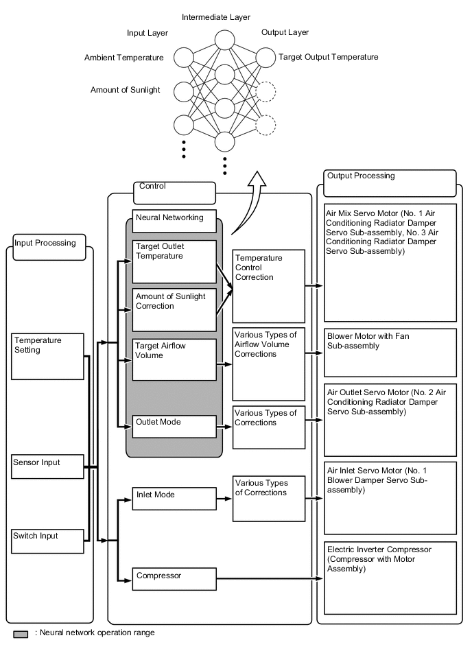
Previously, in automatic air conditioning systems without neural network control, the air conditioning amplifier assembly determined the required outlet air temperature and blower air volume in accordance with the calculation formula that has been obtained based on information received from the sensors. However, because the senses of a person are rather complex, a given temperature is sensed differently, depending on the environment in which the person is situated. For example, a given amount of solar radiation can feel comfortably warm in a cold climate, or extremely uncomfortable in a hot climate. Therefore, as a technique for effecting a higher level of control, a neural network has been adopted in the automatic air conditioning system. With this technique, the data that has been collected under varying environmental conditions is stored in the air conditioning amplifier assembly. The air conditioning amplifier assembly can then effect control to provide enhanced air conditioning comfort.
-
The neural network control consists of neurons in the input layer, intermediate layer and output layer. The input layer neurons process the input data of the ambient temperature, the amount of sunlight, and the room temperature based on the outputs of the switches and sensors, and output them to the intermediate layer neurons. Based on this data, the intermediate layer neurons adjust the strength of the links among the neurons. The sum of these is then calculated by the output layer neurons in the form of the required outlet temperature, solar correction, target airflow volume and outlet mode control volume. Accordingly, the air conditioning amplifier assembly controls the servo motors and blower motor in accordance with the control volumes that have been calculated by the neural network control.
-
-
Electric Inverter Compressor Control
-
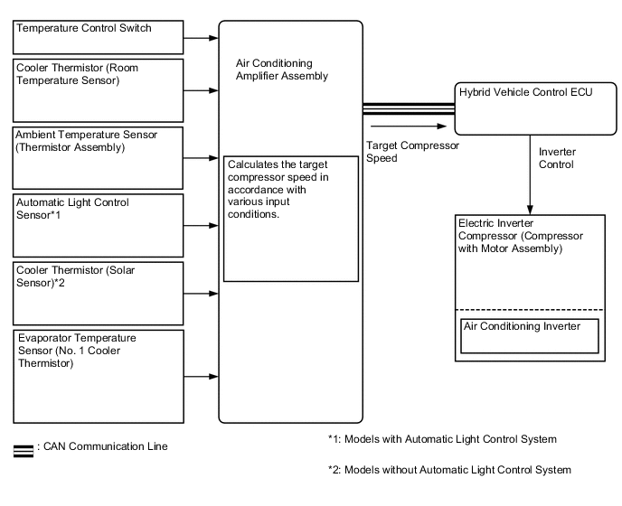
The air conditioning amplifier assembly calculates the target compressor speed based on the target evaporator temperature (calculated from the temperature control switch, cooler thermistor (room temperature sensor), ambient temperature sensor (thermistor assembly), automatic light control sensor*1 and cooler thermistor (solar sensor)*2) and the actual evaporator temperature detected by the evaporator temperature sensor (No. 1 cooler thermistor). Then, the air conditioning amplifier assembly transmits the target speed to the hybrid vehicle control ECU. The hybrid vehicle control ECU controls the air conditioning inverter based on the target speed data in order to control the electric inverter compressor (compressor with motor assembly) to a speed that suits the operating condition of the air conditioning system.
-
The air conditioning amplifier assembly calculates the target evaporator temperature, which includes corrections based on the temperature control switch, cooler thermistor (room temperature sensor), ambient temperature sensor (thermistor assembly), automatic light control sensor*1, cooler thermistor (solar sensor)*2 and evaporator temperature sensor (No. 1 cooler thermistor). Accordingly, the air conditioning amplifier assembly controls the compressor speed to an extent that does not inhibit the proper cooling performance or defogging performance. As a result, comfort and low fuel consumption can be realized.
-
The electric inverter compressor (compressor with motor assembly) is supplied with high-voltage direct current, and it uses high-voltage alternating current internally. If an open or short circuit occurs in the electric inverter compressor (compressor with motor assembly), the hybrid vehicle control ECU will cut off the air conditioning inverter circuit.
-
*1: Models with automatic light control system
-
*2: Models without automatic light control system
-
-
-
Refrigerant Volume Detection Control
-
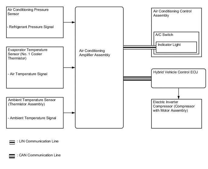
The air conditioning amplifier assembly judges the volume of refrigerant from the ambient temperature, refrigerant pressure and the temperature of the cool air past the No. 1 cooler evaporator sub-assembly. When the air conditioning amplifier assembly judges refrigerant shortage, it turns off the indicator light of the A/C switch. At that time, the electric inverter compressor (compressor with motor assembly) stops operating.
-
-
PTC Heater Control
-
The on/off function of the PTC heater (quick heater assembly) is controlled by the air conditioning amplifier assembly in accordance with the engine coolant temperature, engine speed, air mix setting and electrical load.
-
For example, the number of the operating PTC heater (quick heater assembly) varies with engine coolant temperature as in the graph below.
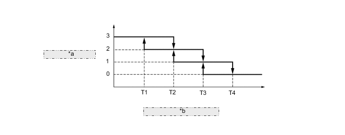
*a Number of PTC Heater Operation *b Engine Coolant Temperature
-
-
Eco Drive Mode Control
-
During eco drive mode control, the air conditioning amplifier assembly restricts the air conditioning system performance under specified conditions, thus improving fuel economy.
-
Eco drive mode control is activated when the ECO MODE switch (eco switch assembly) is pressed, and then restricts the air conditioning system performance as described below.
Control Outline Inside/Outside Air Switch Control Automatically switches the air inlet port to recirculation mode when the outside air temperature is equal to or higher than a predetermined temperature and reduces the power consumption. Blower Level Control Sets the blower level in AUTO mode lower than normal, and suppresses the power consumption. PTC Heater Control Suppresses the power consumption. Heating Restriction Control Changes the air outlet temperature by entering eco drive mode during heating and increases the amount of engine-off time when the drive mode is in ECO, thus improving fuel economy. Compressor Speed Restriction Control Restricts the maximum compressor speed during cooling and reduces the power consumption.
-
-
-
CONSTRUCTION
-
Air Conditioning Control Assembly
-
The push button and dial type air conditioning control assembly is used.
-
The air conditioning control assembly with Liquid Crystal Display (LCD) is used to ensure excellent visibility.
-
The temperature control can be set independently for the driver and front passenger sides.
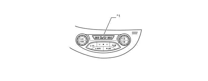
Text in Illustration *1 LCD - -
-
-
Air Conditioning Unit Assembly
-
The air conditioning unit consists of the heater radiator unit sub-assembly, No. 1 cooler evaporator sub-assembly, evaporator temperature sensor (No. 1 cooler thermistor), PTC heater (quick heater assembly) and damper servo sub-assemblies.
-
A semi-center location air conditioning unit, in which the heater radiator unit sub-assembly and No. 1 cooler evaporator sub-assembly are placed in the vehicle's longitudinal direction, is used.
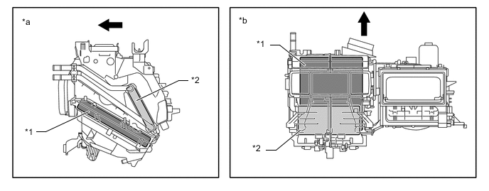
Text in Illustration *1 No. 1 Cooler Evaporator Sub-assembly *2 Heater Radiator Unit Sub-assembly *a Side View *b Top View 
Front - - -
A partial recirculation system is used. This system has an air inlet control door (sub) in the air inlet duct. Thus, it is able to cycle a small volume of recirculated air even in the FRESH mode, thus enhancing heating performance. When the blower switch is on, the suction force of the blower fan opens this air inlet control door (sub).
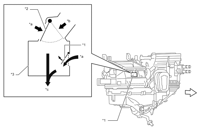
Text in Illustration *1 Air Inlet Control Door (Sub) *2 Air Inlet Control Door *3 Air Inlet Duct - - *a RECIRC *b FRESH *c To Blower Fan - - Air Flow 
Front
-
-
No. 1 Cooler Evaporator Sub-assembly
-
A Revolutionary super-Slim structure (RS) evaporator is used. By placing the tanks at the top and the bottom of the No. 1 cooler evaporator sub-assembly and by using a micropore tube construction, the following effects have been achieved:
-
Heat exchanging efficiency is ensured.
-
Temperature distribution is made uniform.
-
The No. 1 cooler evaporator sub-assembly is made thinner.
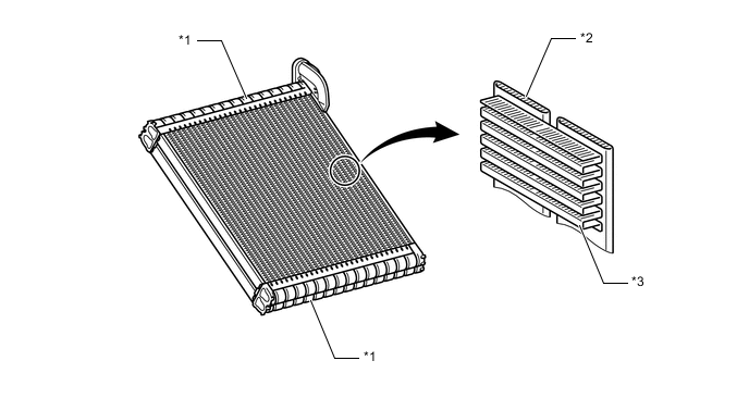
Text in Illustration *1 Tank *2 Micropore Tube *3 Cooling Fin - - -
-
-
Evaporator Temperature Sensor (No. 1 Cooler Thermistor)
-
The evaporator temperature sensor (No. 1 cooler thermistor) detects the temperature of the cool air immediately past the No. 1 cooler evaporator sub-assembly in the form of resistance changes, and outputs it to the air conditioning amplifier assembly.
-
-
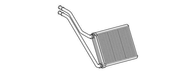
Heater Radiator Unit Sub-assembly
-
The heater radiator unit sub-assembly has been made more compact and performance has been improved by making the core section finer and improving the shapes of the tank section and flow section. Also, the environment has been considered. By using aluminum as the material, the amount of the environmental burden disposal (lead) has been reduced.
-
-
Blower Motor with Fan Sub-assembly
-
High magnetic force magnets and ball bearings are used to achieve a compact and lightweight assembly.
-
-
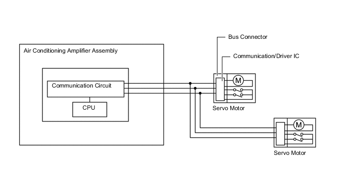
Bus Connector (Air Conditioning Harness Assembly)
-
The bus connector (air conditioning harness assembly) has a built-in communication/driver IC, which communicates with each servo motor connector, actuates the servo motor and has a position detection function. This enables bus communication for the servo motor wire harness to achieve a more lightweight construction and a reduced number of wires.
-
-
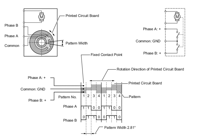
Servo Motor
-
In contrast to the previous type that detects the position by way of a potentiometer voltage, the pulse pattern type servo motor detects the relative position by way of the 2-bit on/off signals.
-
The forward and reverse revolutions of this motor are detected by way of 2 phases, A and B, which output 4 types of patterns. The air conditioning amplifier assembly counts the number of pulse patterns in order to determine the stopped position.
-
-
Cooler Condenser Assembly
-
A Global Inner-fin Condenser (GIC) is provided. This condenser has tubes with high-density inner fins, and outer fins which allow the use of thinner cores, contributing to the efficiency of cooling performance.
-
The cooler condenser assembly consists of 2 cooling portions: a condensing portion and a super-cooling portion. These portions are integrated with a gas-liquid separator (modulator). This cooler condenser assembly uses a sub-cool cycle that offers excellent heat-exchange performance.
-
In the sub-cool cycle, after the refrigerant passes through the condensing portion of the cooler condenser assembly, both the liquid refrigerant and the gaseous refrigerant that could not be liquefied are cooled again in the super-cooling portion. Thus, the refrigerant is sent to the No. 1 cooler evaporator sub-assembly in an almost completely liquefied state.
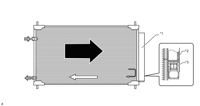
Text in Illustration *1 Modulator *2 Desiccant *3 Filter - - Condensing Portion Super-cooling Portion 
Gaseous Refrigerant 
Liquid Refrigerant
-
-
Electric Inverter Compressor (Compressor with Motor Assembly)
-
An ES14 type electric inverter compressor (compressor with motor assembly) that is driven by a motor is used. The basic construction and operation of this compressor are the same as the ordinary scroll compressor, except that it is driven by an electric motor.
-
The electric inverter compressor (compressor with motor assembly) consists of a spirally wound fixed scroll and rotating scroll that form a pair, a brushless motor, an oil separator, a motor shaft and air conditioning inverter.
-
The air conditioning inverter is integrated with the electric inverter compressor (compressor with motor assembly). This inverter operates the compressor on the HV battery. As a result, the air conditioning system is actuated without depending on the operation of the engine, thus realizing a comfortable air conditioning system and low fuel consumption.
-
The fixed scroll is integrated with the housing. Because the rotation of the shaft causes the rotating scroll to revolve while maintaining the same posture, the volume of the space that is partitioned by both scrolls varies to perform the suction, compression and the discharge of the refrigerant gas. Locating the suction port directly above the scrolls enables direct suction, thus realizing improved suction efficiency. Containing a built-in oil separator, this compressor is able to separate the compressor oil that is intermixed with the refrigerant and circulates in the refrigeration cycle, thus realizing a reduction in the oil circulation rate.
-
Low-moisture permeation hoses are used for the suction and discharge hoses at the compressor in order to minimize the entry of moisture into the refrigeration cycle.
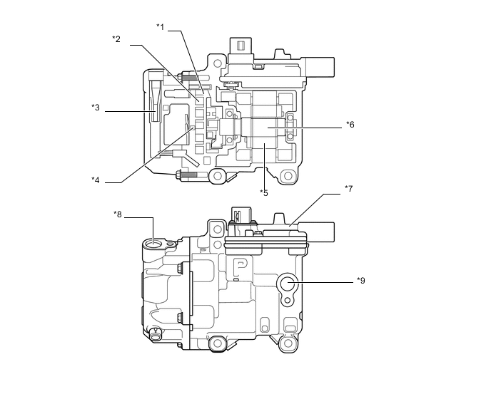
Text in Illustration *1 Rotating Scroll *2 Fixed Scroll *3 Oil Separator *4 Discharge Port *5 Brushless Motor *6 Motor Shaft *7 Air Conditioning Inverter *8 Discharge Hose Port *9 Suction Hose Port - - CAUTION:
In order ensure the proper insulation of the internal high-voltage portion of the electric inverter compressor (compressor with motor assembly) and the compressor housing, this model has adopted a compressor oil (ND11) with a high level of insulation performance. Therefore, never use a compressor oil other than the ND11 type compressor oil or its equivalent.
-
-
Sub-cool Accelerator Type Tube (Models using HFO-1234yf refrigerant)
-
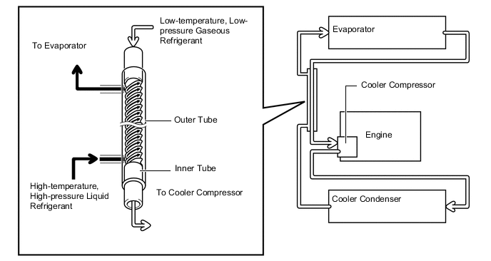
A sub-cool accelerator type tube is used to enhance air conditioning cooling performance. It functions as a heat exchanger by making use of the temperature difference between the gaseous refrigerant and liquid refrigerant.
-
The sub-cool accelerator type tube has a double-pipe construction. Helical grooves are embossed into the outer wall of the inner tube. Low-temperature and low-pressure gaseous refrigerant passes through the inner tube. High-temperature and high-pressure liquid refrigerant circulates between the inner tube and outer tube in the gap created by the grooves. Because of the temperature difference, heat exchange occurs.
-
The high-temperature and high-pressure liquid refrigerant circulate along the helical grooves causing the refrigerant to remain in contact with the outer wall of the inner tube for a longer period of time. This achieves an ample exchange of heat.
-
By lowering the temperature of the refrigerant that has passed through the cooler condenser assembly, more liquid refrigerant is supplied to the evaporator and the evaporator is also kept cooler. This enables an enhanced air conditioning cooling effect.
-
-
Clean Air Filter
-
A pollen removal type clean air filter is used to remove dust, pollen and other micron particles from air entering from outside the vehicle to provide a comfortable cabin of clean air. The clean air filter is installed in the upper section of the blower motor with fan sub-assembly.
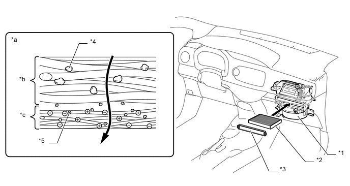
*1 Blower Motor with Fan Sub-assembly *2 Clean Air Filter *3 Air Filter Case *4 Pollen *5 Micron Particle - - *a Image of Clean Air Filter *b Large Foreign Object Filter Layer *c Electret Layer - -
-
-
PTC Heater (Quick Heater Assembly)
-
The PTC heater (quick heater assembly) is located above the heater radiator unit sub-assembly in the air conditioning unit.
-
The PTC heater (quick heater assembly) consists of a Positive Temperature Coefficient (PTC) element, an aluminum fin and a brass plate. When current is applied to the PTC element, it generates heat to warm the air that passes through the unit.
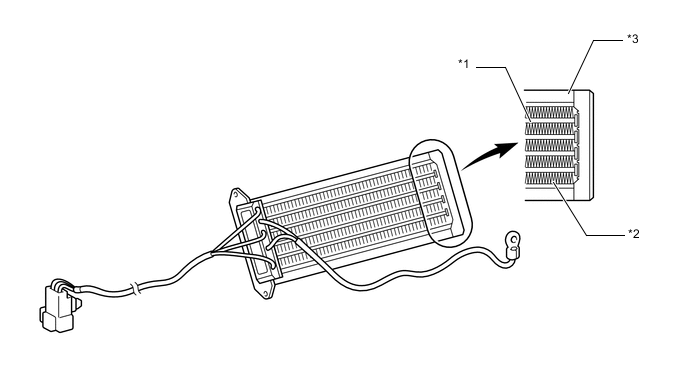
Text in Illustration *1 PTC Element *2 Aluminum Fin *3 Brass Plate - -
-
-
Ambient Temperature Sensor (Thermistor Assembly)
-
The ambient temperature sensor (thermistor assembly) detects the ambient temperature based on changes in the resistance of its built-in thermistor. This signal is used by the air conditioning amplifier assembly.
-
-
Cooler Thermistor (Room Temperature Sensor)
-
The cooler thermistor (room temperature sensor) detects the room temperature based on changes in the resistance of its built-in thermistor. This signal is used by the air conditioning amplifier assembly.
-
-
Automatic Light Control Sensor*1 / Cooler Thermistor (Solar Sensor)*2
-
The automatic light control sensor*1 or the cooler thermistor (solar sensor)*2 detects (in the form of changes in the current that flows through the built-in photo diode) the changes in the amount of sunlight and outputs these sunlight strength signals to the air conditioning amplifier assembly.
-
*1: Models with automatic light control system
-
*2: Models without automatic light control system
-
-
-
Air Conditioner Pressure Sensor
-
The air conditioner pressure sensor detects the refrigerant pressure and outputs it to the air conditioning amplifier assembly in the form of voltage changes.
-
-
-
OPERATION
-
Mode Position and Door Operation
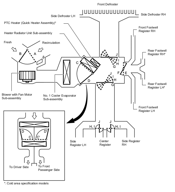
Tech Tips
This illustration is a model diagram showing the doors positions in each mode. The parts layout and the number of the doors in the illustration are different from those of the actual system.
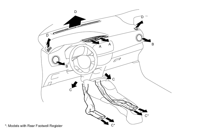
Control Damper Operation Position Damper Position Operation Air Inlet FRESH A Brings in fresh air. RECIRCULATION B Recirculates internal air. Air Mix MAX COLD to MAX HOT C to D, C' to D' Varies the mixture ratio of the fresh air and the recirculation air in order to regulate the temperature continuously from HOT to COLD. Mode 
FACE E, J Air blows out of the center register and side register. 
BI-LEVEL F, J Air blows out of the center register, side registers, and front and rear* footwell register ducts. 
FOOT F, I Air blows out of the front and rear* footwell register ducts and side register. In addition, air blows out slightly from the front defroster and side defroster. 
FOOT/DEF F, H Defrosts the windshield through the front defroster, side defroster and side register, while air is also blown out from the front and rear* footwell register ducts. 
DEF E, G Defrosts the windshield through the front defroster, side defroster and side register.
-
*: Cold area specification models
-
-
Air Outlets and Airflow Volume
Indication Mode A B C D Center Side Foot Defroster FACE 
- - BI-LEVEL 
- FOOT - 
FOOT/DEF - DEF - - Tech Tips
The size of the circle ○ indicates the proportion of airflow volume.
-
Side Register
-
The side register has been adopted which allows the user to change the airflow modes and airflow direction/amount at will by operating a dial.
-
Moving the dial at the center of the side register operates the vanes inside the side register. In this way, the airflow area can be adjusted at will by the user, enabling increased comfort.
-
Airflow direction can be adjusted by moving the dial at the center of the side register up, down, left, or right.
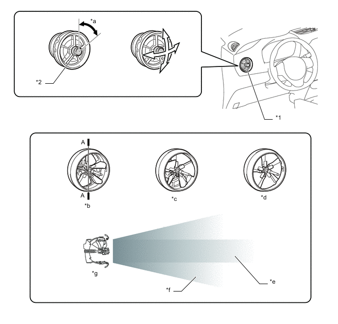
*1 Side Register *2 Dial *a 60° *b Spot Airflow *c Wide Airflow *d Shut *e Image of the air volume (Spot Airflow) *f Image of the air volume (Wide Airflow) *g A-A Cross Section - - By rotating the center dial, the airflow area can be adjusted. By moving the dial up, down, left or right, the direction of airflow can be adjusted.
-
-
Compressor Operation
-
The electric inverter compressor (compressor with motor assembly) performs suction, compression and discharge of refrigerant gas as described in the table below.
Stroke Operation Suction As the capacity of the compression chamber, which is created between the rotating scroll and the fixed scroll, increases in accordance with the revolution of the rotating scroll, refrigerant gas is drawn in from the intake port. Compression From the state at which the suction process has been completed, as the revolution of the rotating scroll advances further, the capacity of the compression chamber decreases gradually. Consequently, the refrigerant gas that has been drawn in becomes compressed gradually and is sent to the center of the fixed scroll. The compression of the refrigerant gas is completed when the rotating scroll completes approximately 2 revolutions. Discharge When the compression of the refrigerant gas is completed and the refrigerant pressure becomes high, the refrigerant gas discharges through the discharge port located in the center of the fixed scroll by pushing the discharge valve. 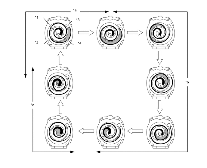
Text in Illustration *1 Discharge Port *2 Rotating Scroll *3 Intake Port *4 Fixed Scroll *a Suction *b Compression *c Discharge - -
-
-
-
DIAGNOSIS
-
The air conditioning amplifier assembly has a self-diagnosis function. It stores any operation failures in the air conditioning system memory in the form of Diagnostic Trouble Codes (DTCs). For details, refer to the Repair Manual.
-