PARKING ASSIST MONITOR SYSTEM
-
FUNCTION OF MAIN COMPONENTS
-
The parking assist monitor system consists of the following parts:
Component Function Radio and Display Receiver Assembly Displays the image transmitted by the rear television camera assembly on the screen. Rear Television Camera Assembly Captures images in rear of the vehicle and outputs visual signals to the radio and display receiver assembly. Shift Lever Position Sensor Transmits the shift position signal to the hybrid vehicle control ECU. Main Body ECU (Multiplex Network Body ECU) Outputs the back door courtesy light switch signal to the radio and display receiver assembly. Hybrid Vehicle Control ECU Outputs the shift position signal to the radio and display receiver assembly. Back Door Courtesy Light Switch Detects whether the back door is opened or closed. Central Gateway ECU (Network Gateway ECU)* Relays and transmits each CAN communication data signal. *: Models with Toyota Safety Sense
-
-
OPERATING CONDITION
-
Parking assist monitor system operates the following conditions are met:
-
The ignition switch ON (IG).
-
The shift lever is moved to R.
-
The back door completely closed.
-
-
-
FUNCTION
-
Parking Guide Line on Screen
-
When the rear view is being displayed on the radio and display receiver assembly, the guide lines for park assist are also displayed.
-
A description of the parking guide lines is provided in the following diagram.
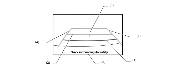
Item Description (1) Distance Guide Line (Red) Indicates a position on the ground about 0.5 m (1.6 ft.) behind the rear bumper. (2) Distance Guide Line (Blue) Indicates a position on the ground about 1.0 m (3.3 ft.) behind the rear bumper. (3) Vehicle Center Guide Line (Blue) Indicates the estimated position on the ground of the center of the vehicle. (4) Vehicle Width Guide Lines (Blue) Indicate the estimated vehicle width. (a) Warning Message Display Area Area where warning messages are displayed.
-
-
Area Displayed on Screen
-
On the display, objects on the right of the vehicle appear on the right side of the display panel, and objects on the left of the vehicle appear on the left side of the display panel.
-
The rear television camera assembly uses a wide-angle lens. The perceived distance from images that appear on the screen differs from the actual distance.
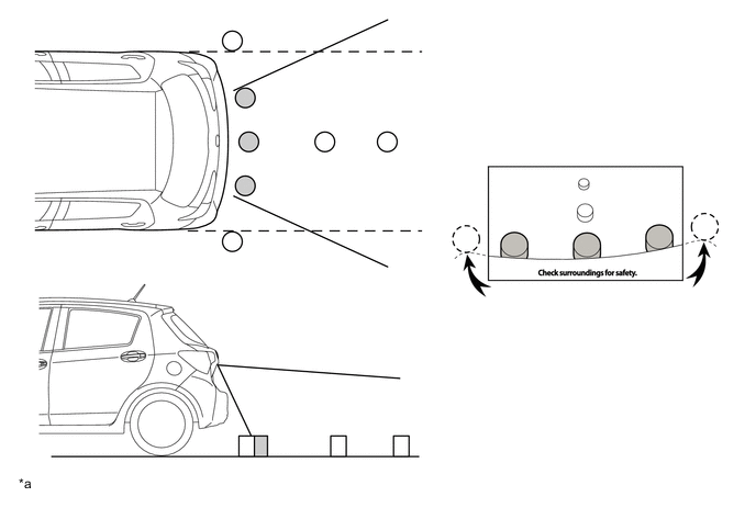
*a The illustrations shown are examples only. The illustrations may differ from the actual vehicle screens. - - Note
The area displayed on the screen may vary in accordance with vehicle status or road conditions. The area covered by the rear television camera assembly is limited. The rear television camera assembly does not show objects close to either corner of the bumper or under the bumper.
-
-
-
CONSTRUCTION
-
Rear Television Camera Assembly
-
The rear television camera assembly consists of a wide-angle lens and a Complementary Metal Oxide Semiconductor (CMOS).
-
An image captured by the rear television camera assembly lens is converted into electrical signals according to the light intensity by using the CMOS image element, and the signals are then output to the radio and display receiver assembly.
-
The image output from the rear television camera assembly is reversed to much the rear view seen from the inner rear view mirror assembly. Therefore, the rear view actually seen is displayed on the screen in the horizontal reverse.
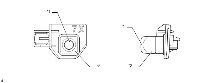
*1 Wide-angle Lens *2 Rear Television Camera Assembly
-
-