POWER STEERING SYSTEM
-
FUNCTION OF MAIN COMPONENTS
-
The main components of the EPS system are as follows:
Component Function Electric Power Steering Column Sub-assembly Torque Sensor Detects the twist of the torsion bar, calculates the torque that is applied to the torsion bar by changing it into an electrical signal, and outputs this signal to the power steering ECU assembly. Reduction Mechanism Reduces the speed of the power steering motor through the use of a worm gear and a wheel gear and transmits it to the column shaft. Power Steering Motor Assembly Generates assist torque in accordance with a current received from the power steering ECU assembly. Power Steering ECU Assembly Actuates the power steering motor mounted on the steering column assembly to provide assist torque, based on the signals received from various sensors and ECUs. Hybrid Vehicle Control ECU Transmits the ready status signal to the power steering ECU assembly. Brake Booster with Master Cylinder Assembly Skid Control ECU Transmits the vehicle speed signal to the power steering ECU assembly. Combination Meter Assembly EPS Warning Light Illuminates to alert the driver when the power steering ECU assembly detects a malfunction in the EPS system. Buzzer Sounds to alert the driver when the power steering ECU assembly detects a malfunction in the EPS system.
-
-
SYSTEM CONTROL
-
The EPS system has the following controls:
Control Outline Basic Control Calculates the assist current from the steering torque value and the vehicle speed, and actuates the power steering motor assembly. Compensation Control Compensates with a force, according to the driver's steering maneuver, improving the comfort of steering.
-
-
CONSTRUCTION
-
Steering Column Assembly
-
The steering column assembly includes a torque sensor; power steering motor and reduction mechanism.
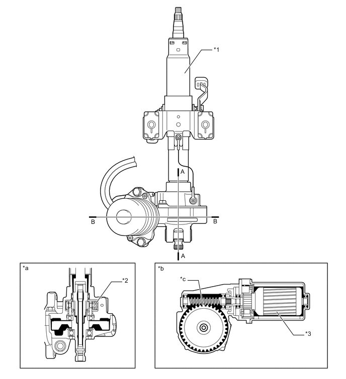
Text in Illustration *1 Steering Column Assembly *2 Torque Sensor *3 Power Steering Motor - - *a A-A Cross Section *b B-B Cross Section *c Reduction Mechanism - - -
The torque sensor with Hall ICs is used.
-
The torque sensor is built into the steering column. A multi-pole magnet is mounted to the input shaft, and a yoke is mounted to the output shaft. The input and output shafts are joined by the torsion bar.
-
The magnetic convergence ring assembly contains Hall ICs, which face opposite to each other. The system detects the steering direction in accordance with the direction of the magnetic flux that the amount of change in the magnetic flux density based on the relative displacement of the multi-pole magnet and the yoke. The power steering ECU assembly monitors the torque sensor signals that are output by the two Hall ICs to detect malfunctions.
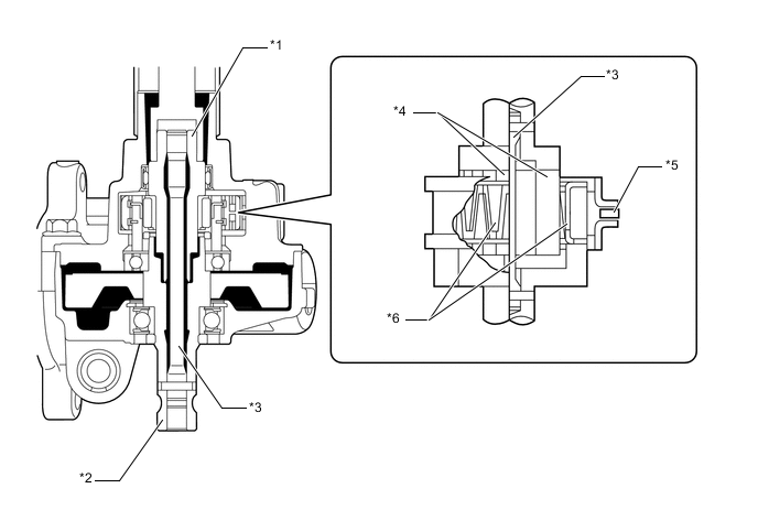
Text in Illustration *1 Input Shaft *2 Output Shaft *3 Torsion Bar *4 Multi-pole Magnet *5 Hall IC *6 Yoke 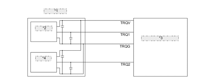
*1 Torque Sensor *2 Hall IC 1 *3 Power Steering ECU Assembly *4 Hall IC 2 Note
After replacing the electric power steering column assembly, the power steering motor assembly or the power steering ECU assembly, calibration of the torque sensor zero point is required. For details, refer to the Repair Manual.
-
A low inertia, low noise, and high power output power steering motor is used.
-
The power steering motor consists of a rotor, stator and motor shaft.
-
The torque that is generated by the power steering motor is transmitted via the joint to the reduction mechanism.
-
The reduction mechanism reduces the speed of the power steering motor via the worm gear and the wheel gear, and transmits it to the column shaft.
-
The wheel gear is made of a high strength, low friction, and low wear plastic material, to realize low noise and a lightweight construction.
-
The worm gear is supported by the ball bearings in order to reduce noise and frictions.
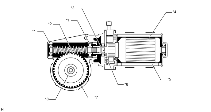
Text in Illustration *1 Ball Bearing *2 Worm Gear *3 Joint *4 Rotor *5 Stator *6 Motor Shaft *7 Wheel Gear *8 Column Shaft
-
-
-
OPERATION
-
Straight line Driving
-
If the vehicle is driven straight and the driver does not turn the steering wheel, the yoke is located in the center between the N and S poles of the multi-pole magnet. Thus, no magnetic flux passes between the Hall ICs. In this case, the Hole ICs output a specified voltage to the power steering ECU assembly, to indicate that the steering wheel is in the neutral position. Therefore, it does not apply current to the motor.
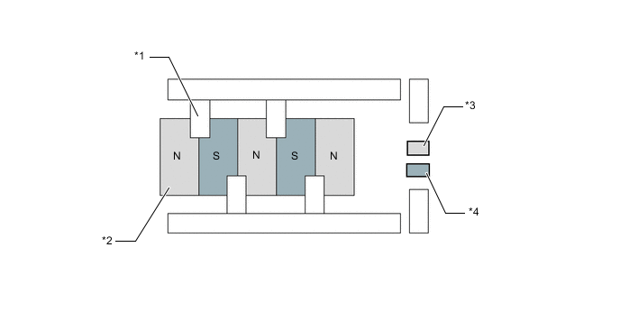
Text in Illustration *1 Yoke *2 Multi-pole Magnet *3 Hall IC 1 *4 Hall IC 2
-
-
When Steering
-
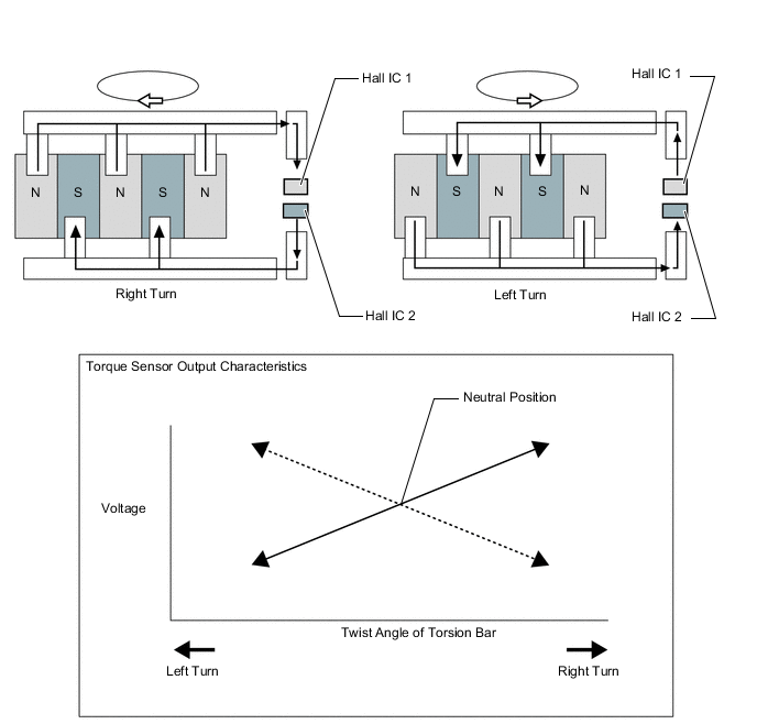
When a driver turns the steering wheel to the right or left, the twist that is created in the torsion bar creates a relative displacement between the multi-pole magnet and the yoke.
-
At this time, the magnetic flux from the N to S pole of the multi-pole magnet passes between the Hall ICs. The system detects the steered direction of the steering wheel in accordance with the direction opposite to each other. As a result, the output characteristics of the 2 Hall ICs are constantly opposite each other. The system monitors the different outputs of these Hall ICs in order to detect malfunction.
-
The magnetic flux density becomes higher as it gets closer to the center of the respective pole. A Hall IC converts these magnetic flux fluctuations into voltage fluctuations, in order to transmit the turning torque of the steering wheel to the power steering ECU assembly.
-
-
-
FAIL-SAFE
-
If the power steering ECU assembly detects a malfunction in the EPS system, the power steering ECU assembly illuminates the EPS warning light and sounds the buzzer to inform the driver.
-
If a system malfunction is detected, the power steering ECU assembly changes control mode to fail-safe mode. For details, refer to the Repair Manual.
-
-
DIAGNOSIS
-
The power steering ECU assembly will also store a Diagnostic Trouble Code (DTC). The DTC can be accessed through the use of an Global TechStreem (GTS). For details, refer to the Repair Manual.
-