NAVIGATION SYSTEM / MULTI INFORMATION SYSTEM
-
FUNCTION OF MAIN COMPONENTS
Component Function Radio and Display Receiver Assembly Receives navigation system data from the navigation ECU to display information on the screen and output sounds. Extension Box (Navigation ECU) The built-in navigation ECU transmits navigation system control data to the radio and display receiver assembly. Navigation Antenna Assembly Receives signals from GPS satellites and transmits them to the navigation ECU. Amplifier Antenna Assembly Amplifies radio broadcasting signals from the radio antenna and sends them to the radio and display receiver assembly. Combination Meter Assembly Transmits vehicle speed signals to the radio and display receiver assembly. Amplifier Microphone Assembly Transmits voice signals to the radio and display receiver assembly. Steering Pad Switch Assembly Transmits the operation signals from the switches to the radio and display receiver assembly. No. 1 Stereo Jack Adapter Assembly Transmits information about the USB device connected to the USB port to the navigation ECU assembly. Parking Brake Switch Assembly Transmits the on/off signal of the parking brake switch assembly to the radio and display receiver assembly. Rear Television Camera Assembly*1 Captures the view behind the vehicle and transmits the image to the radio and display receiver assembly. Stereo Component Amplifier Assembly*2 Amplifies audio signals sent from the radio and display receiver assembly and sends them to the speakers.
-
*1: Models with parking assist monitor system
-
*2: Models with 8-speaker system
-
-
FUNCTION
-
Navigation Screen
-
The navigation computer calculates the present position and direction of travel, determines a route and calculates the driving distance based on the following information sources:
-
Map data in the navigation ECU
-
Global Positioning System (GPS) satellites
-
Built-in gyro sensor
-
Vehicle speed signal
-
Reverse signal
-
Parking brake signal
-
Radio Data System Traffic Message Channel (RDS-TMC) signal
Item Outline Map Display Taillight-interlocked Map Color Change Changes the color of the map screen when the taillights are turned on. North Up/Heading Up
-
If North Up is selected, north is always at the top of the map.
-
If Heading Up is selected, the direction the vehicle is traveling is at the top of the map.
3D Display Displays a 3-dimensional (3D) view of the map. Zoom In/Zoom Out Change the area of the map displayed on the screen. Street Name Indication on Scrolled Map Displays the street name and city name even when the map screen is being scrolled. Road Number Sign Board Display Displays the road number on the map. Point Of Interest (POI) Display Displays selected types of POI as marks on the map. RDS-TMC Display Displays RDS-TMC icons, arrows, popup messages and indicators when the RDS-TMC service is being received. Destination Search Preset Destination Memory Search Sets a pre-registered point as a destination point while driving. Address Search Destination information can be entered in the following order: area, town name, street name and house number. Previous Destination Search Stores the coordinates, names, and dates of up to 100 locations that have been set as destinations. Online Database Destination Search The navigation system can use an internet search engine to set a destination using the most up-to-date information. Point Of Interest Search A destination can be set in 4 ways:
-
By selecting a category and then a location.
-
By entering a name and then selecting a location.
-
By selecting a POI on the map.
-
By using the online search through connected services.
Map Search A destination can be set by scrolling the cursor on the map. Address Book (Memory Point) Search A destination can be set from the registered Address Book (Memory Point). Coordinate Search A destination can be input by entering its coordinates. Route Search Multiple Destination Setting Multiple destinations can be set. The sequence of the destinations can be rearranged as well. Search Condition Designation Searches for fast, short and ecological routes. Destination Reordering Changes the order of destinations when more than one destination is selected. Detour Search Changes the route to detour around a section of the route. Avoidance Area Searches for a route that avoids a designated area. Auto Avoid Traffic Search Automatically changes to another route to avoid heavy congestion. Guidance Voice Guidance Provides voice guidance about the distance and the direction of travel to a destination point based on road conditions and vehicle speed. Next Turn Guidance Provides guidance about the distance to the next turn and indicates the direction of the turn using an arrow. Motorway Exit or Junction Display When the vehicle approaches an exit or junction, the motorway guidance screen will be displayed. Distance-to-destination Display Displays the distance from the present location to the destination. Route Information Bar Display Displays the following information:
-
Street name of the current location
-
Distance and travel time to the destination
-
Distance to the destination and estimated time of arrival
-
Distance to the destination and an arrow facing the destination (when off the route during the guidance)
Traffic Bar Display Displays traffic information of congestions or accidents on the route using the traffic bar. -
-
-
Fuel Consumption Screen
-
The fuel consumption screen is displayed as illustrated below. This screen has the display functions listed below:
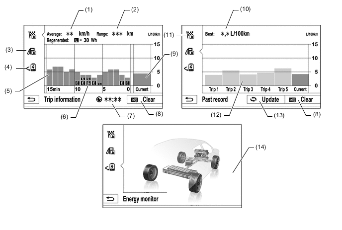
Item Outline (1) Average Speed Displays an average speed value that has been calculated by the combination meter assembly, which is based on the distance driven and time elapsed since the ignition switch was turned to ON. (2) Range Displays the approximate drivable distance. (3) Past Record Switch Changes to the Past Record (per trip) fuel consumption screen. (4) Energy Switch Changes the screen to the energy monitor screen. (5) Average Per Minute Fuel Consumption
-
Displays the value that has been calculated by the combination meter assembly, which is based on the driven distance and the volume of fuel consumed (fuel injection signal) since the ignition switch was turned to ON.
-
Displays the average fuel consumption for the last minute, or since clear was last selected.
(6) Recovered Energy
-
Indicates the recovered energy for 1 minute with "E" symbols.
-
The recovered energy status is calculated by the power management control ECU.
(7) Elapsed Time Displays an elapsed time value that has been calculated by the combination meter assembly, which is based on the time elapsed since the ignition switch was turned to ON. (8) Clear Switch Clears all past information. (9) Current Per Minute Fuel Consumption Displays the instantaneous (current) fuel consumption value that has been calculated by the combination meter assembly, which is based on the driven distance and the volume of fuel consumed (fuel injection signal) since the ignition switch was turned to ON. (10) Best Fuel Consumption Displays the best (most economical) per trip fuel consumption. (11) Trip Information Switch Changes to the average per minute fuel consumption screen. (12) Average Per Trip Fuel Consumption
-
Displays the current record and the last 5 average per trip fuel consumption records or the current record and those since clear was last selected.
-
Starts calculating the average fuel consumption when the average fuel consumption displayed on the combination meter assembly is reset.
(13) Update Switch
-
Restarts calculation of the average fuel consumption value.
-
Sends the average fuel consumption reset signal to the combination meter assembly to update the graph.
(14) Energy Monitor Indicates the energy transmission direction, making it possible to confirm the current drive method (engine, motor or both), the power generation status by the engine and status of regenerative energy use.
-
The State Of Charge (SOC) of the battery can be checked on the meter. The meter shows the SOC in 9-levels.
-
Display the energy monitor status that has been calculated by the power management control ECU.
-
-
-
-
DIAGNOSIS
-
For details on the procedure required to enter the Service Menu screen, refer to the Repair Manual.
-