HYBRID TRANSAXLE SYSTEM
-
SYSTEM CONTROL
-
Shift Control System
-
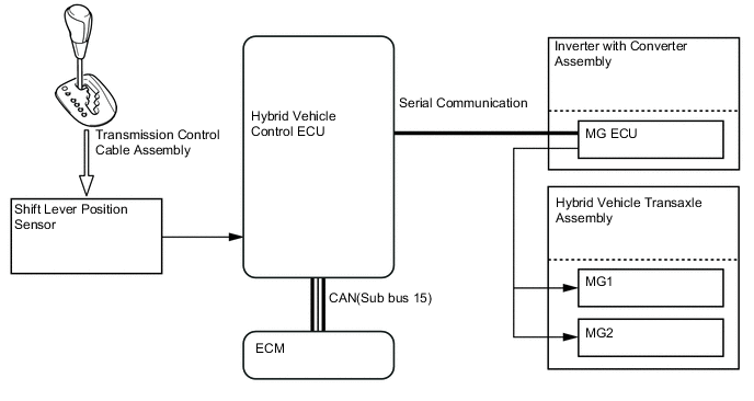
A shift lever position sensor is provided in the transaxle to detect the shift position and sends a corresponding signal to the hybrid vehicle control ECU. Upon receiving this signal, the hybrid vehicle control ECU optimally combines the operation of the engine, MG1 and MG2 in order to produce the respective shift positions (P, R, N, D and B).
-
-
-
CONSTRUCTION
-
Hybrid Vehicle Transaxle Assembly
-
This hybrid vehicle transaxle assembly consists primarily of Motor Generator No. 1 (MG1), Motor Generator No. 2 (MG2), a compound gear unit, a transmission input damper assembly, a counter gear, a final gear, a differential gear unit and an oil pump.
-
This hybrid vehicle transaxle assembly has a 3-shaft configuration. The compound gear unit, a transmission input damper assembly, an oil pump, MG1 and MG2 are provided on the input shaft. The counter driven gear and the final drive gear are provided on the second shaft. The final driven gear and the differential gear unit are provided on the third shaft.
-
The engine, MG1 and MG2 are mechanically joined via the compound gear unit.
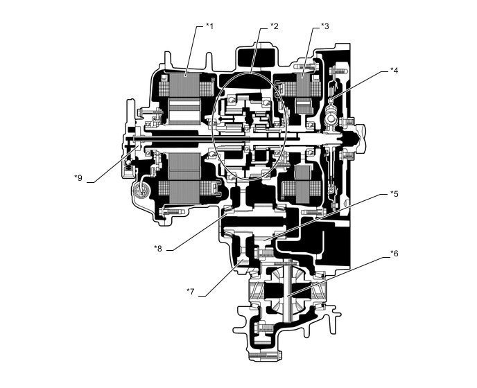
Text in Illustration *1 MG2 *2 Compound Gear Unit *3 MG1 *4 Transmission Input Damper Assembly *5 Final Driven Gear *6 Differential Gear Unit *7 Counter Driven Gear *8 Final Drive Gear *9 Oil Pump - -
-
-
Compound Gear Unit
-
The compound gear unit consists of the power split planetary gear unit and the motor speed reduction planetary gear unit. Each planetary ring gear is integrated with the compound gear. Furthermore, this compound gear is integrated with a counter drive gear and parking gear.
-
The power split planetary gear unit splits the motive force of the engine two ways: one to drive the wheels, and the other to drive MG1, so that MG1 can function as a generator.
-
The motor speed reduction planetary gear unit, whose purpose is to reduce MG2 speed, is used to enable the high-speed, high-output MG2 to adapt optimally to the compound gear.
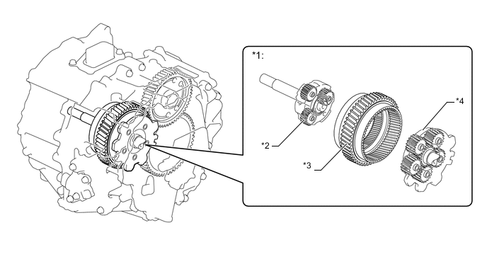
Text in Illustration *1 Compound Gear Unit *2 Power Split Planetary Gear Unit *3 Counter Drive Gear (Compound Gear) *4 Motor Speed Reduction Planetary Gear Unit -
The connection of the sun gear, ring gear and carrier of each planetary gear unit is as shown below.
Item Connection Power Split Planetary Gear Unit Sun Gear MG1 Ring Gear Compound Gear (To Wheels) Carrier Input Shaft (From Engine) Motor Speed Reduction Planetary Gear Unit Sun Gear MG2 Ring Gear Compound Gear (To Wheels) Carrier Fixed 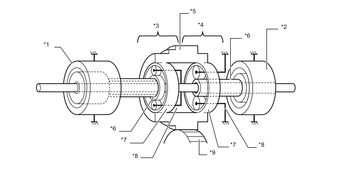
Text in Illustration *1 MG1 *2 MG2 *3 Power Split Planetary Gear Unit *4 Motor Speed Reduction Planetary Gear Unit *5 Counter Drive Gear *6 Sun Gear *7 Ring Gear *8 Carrier *9 Counter Driven Gear - -
-
-
Differential
-
The conical spring adopted pre-load differential gear which is disposed between the side gears and slide gear washer.
-
The load of the conical spring applies a friction force to the sliding area, improving straightline stability and steering stability.
-
Under light load and low differential rotation speeds, due to the friction force of the sliding area, the differential limit torque for the left and right wheels is achieved within the range of the conical spring allowable load. At middle and high load ranges, which are beyond the allowable load of the conical spring, the system performs as an open differential.
-
-
Transmission Input Damper Assembly
-
A transmission input damper assembly that consists of a coil spring with low-twist characteristics is used in order to absorb the torque fluctuation in the motive force of the engine. The torque limiter uses a dry-type, single-plate friction material. Through the use of these parts, a damper construction that excels in absorbing the vibrations of the engine motive force has been achieved.

Text in Illustration *1 Coil Spring *2 Torque Limiter *a Transmission Input Damper Assembly Cross Section - - 
From Engine - -
-
-
Oil Pump Mechanism
-
For lubrication of the compound gear unit and also for supplying oil to MG1 and MG2, a new shape, compact internal oil pump gear without crescent shaped seal is used to reduce the drive loss of the oil pump.
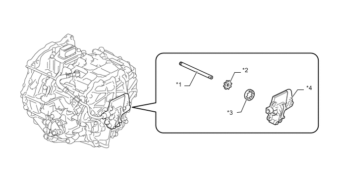
Text in Illustration *1 Oil Pump Drive Shaft *2 Oil Pump Drive Rotor *3 Oil Pump Driven Rotor *4 Oil Pump Cover
-
-
Oil Sling Type Lubrication Mechanism
-
An oil sling type lubrication mechanism has been provided, which lubricates the gears and bearings by catching and transferring the oil released via the rotation of the final driven gear and counter driven gear. This lubrication mechanism helps optimize the discharge amount of oil from the oil pump that is driven by the engine power, contributing to the drive loss reduction.
-
2 oil catch tanks have been provided to temporarily store oil that is transferred from 2 channels. One that temporarily stores oil that is pumped up by the oil pump and is used to supply oil to the motor generator, and the other that temporarily stores oil that is fed by the rotation of the final driven gear and counter driven gear and is used to lubricate the compound gear unit.
-
The oil catch tank for motor generator oil supply pumps up oil that accumulates in the transaxle case and the lower portion of the transaxle housing via the oil pump, feeding oil to the motor generator.
-
The oil catch tank for the compound gear unit lubrication collects oil via the rotation of the final driven gear and counter driven gear, routing the oil to the lubrication holes provided in the transaxle case and transaxle housing to feed oil to the compound gear unit.
-
By employing the oil catch tanks to supply oil to the motor generator and to lubricate the compound gear unit, the oil surface levels inside the transaxle case and transaxle housing can be regulated to the optimal level while the vehicle is driven, reducing the oil stirring loss caused by the final driven gear and counter driven gear.
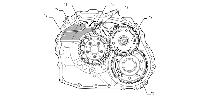
Text in Illustration *1 Oil Supply Pipe *2 Counter Driven Gear *3 Final Driven Gear - - *a Oil Catch Tank for Compound Gear Unit Lubrication *b Oil Catch Tank for Oil Supply *c Lubrication Hole of the Compound Gear Unit - - Oil Flow 
Gear Rotation Direction
-
-
Oil Supply Mechanism
-
An oil supply mechanism has been provided for the MG1 and MG2, which feeds some of the oil, which is discharged by the oil pump located on the input shaft, to the MG1 and MG2.
-
The oil discharged by the oil pump is routed to the two channels; a lubrication path for the compound gear unit and an oil supply path for the MG1 and MG2. For the oil that flows through the oil supply path, it is transferred to the upper portion of the transaxle running through the external oil path provided between the oil pump cover and the transaxle case. After that, the oil flows through the oil pipe located in the upper area of the MG1 and MG2, reaching the MG1 and MG2.
-
The distribution oil amount has been optimized to make the oil supply to the MG1 and MG2 stable.
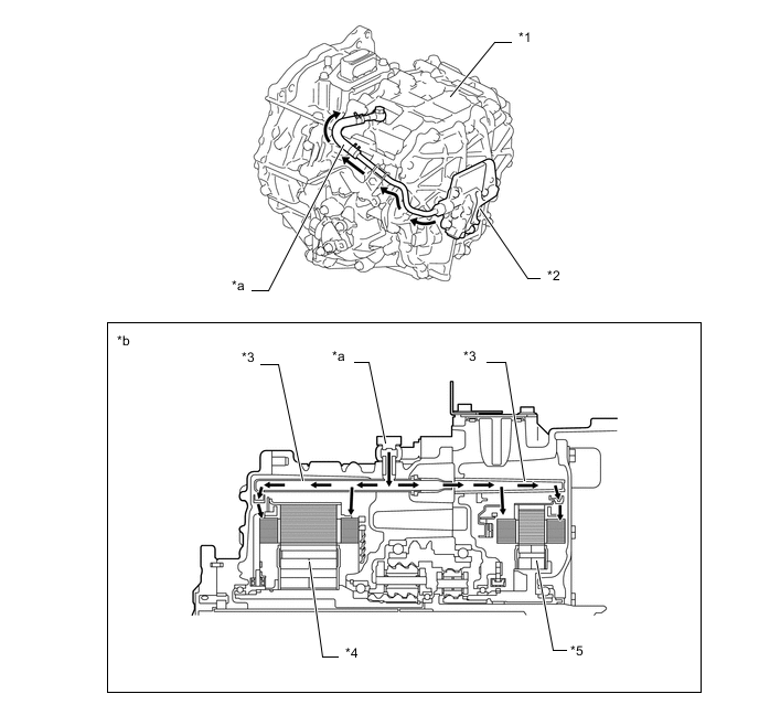
Text in Illustration *1 Transaxle Case *2 Oil Pump Cover *3 Oil Pipe *4 MG2 *5 MG1 - - *a External Oil Path *b Oil Supply Mechanism (Cross Section) Oil Flow - -
-
-
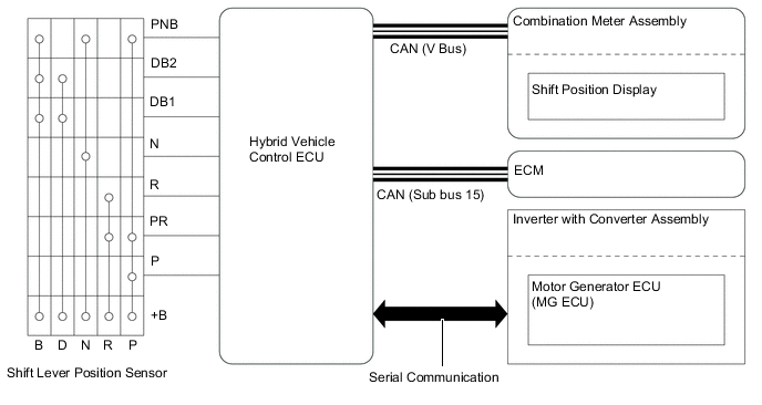
Shift Lever Position Sensor
-
The shift lever position sensor sends the P, R, N, D and B position signals to the hybrid vehicle control ECU.
-
The hybrid vehicle control ECU transmits signals to the combination meter assembly for the shift position display (P, R, N, D and B) in response to the signals received from the sensor.
-
-
Parking Lock Mechanism
-
The parking lock mechanism consists of a parking lock pawl and a parking lock gear which is integrated with the compound gear.
-
When the driver moves the shift lever to P, the parking lock pawl engages with the parking lock gear.
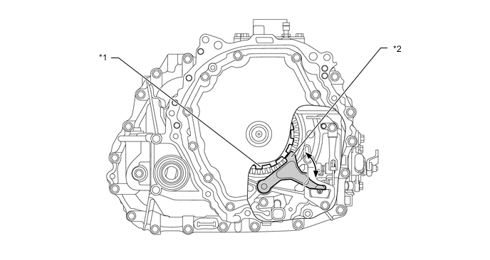
Text in Illustration *1 Parking Lock Gear *2 Parking Lock Pawl
-
-
Shift Lock System
-
The shift lock system is controlled by the shift lock control ECU. It has a key interlock function and a shift lock function. The shift lock system function setting is as follows:
Function without Entry and Start System with Entry and Start System Shift Lock ○ ○ Key Interlock ○ -
-
○: Equipped
-
-: Not equipped
-
-
The shift lock mechanism prevents the shift lever from being moved to any position other than P, unless the ignition switch is ON (IG), and the brake pedal is depressed. This mechanism helps to prevent unintentional acceleration.
-
The key interlock device prevents the key from being pulled out after the ignition switch is turned off, unless the shift lever is moved to P. Thus, the driver is urged to park the vehicle with the shift lever in P.
-
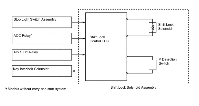
The shift lock system mainly consists of the shift lock control ECU, shift lock solenoid, key interlock solenoid (except models with entry and start system) and shift lock override button.
-
Models with entry and start system: The shift lock control ECU uses the P detection switch to detect the shift lever position, and receives inputs from the stop light switch assembly and power switch. Upon receiving these signals, the shift lock control ECU turns on the shift lock solenoid in order to release the shift lock.
-
Models without entry and start system: The shift lock control ECU uses the P detection switch to detect the shift lever position, and receives inputs from the stop light switch assembly and the ignition switch. Upon receiving these signals, the shift lock control ECU either turns off the key interlock solenoid to release the key interlock, or turns on the shift lock solenoid in order to release the shift lock.
-
-
-
OPERATION
-
Motive Force Transmission Path
-
The motive force created by the engine and MG2 is transmitted by the counter drive gear of the compound gear unit, the counter driven gear, the final drive gear and then the differential gear unit, in order to drive the front wheels.
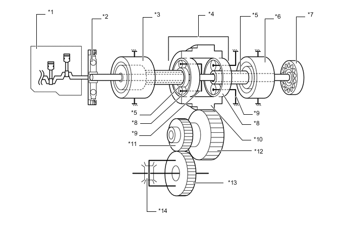
Text in Illustration *1 Engine *2 Transmission Input Damper Assembly *3 MG1 *4 Compound Gear Unit *5 Sun Gear *6 MG2 *7 Oil Pump *8 Ring Gear *9 Carrier *10 Counter Drive Gear (Compound Gear) *11 Final Drive Gear *12 Counter Driven Gear *13 Final Driven Gear *14 Differential Gear Unit
-
-
Engine Motive Force and MG2 Motive Force Transmission Path
-
The engine motive force, which is input by the carrier, is transmitted to the ring gear. The motive force of MG2 is transmitted to the ring gear via the motor speed reduction planetary gear unit. The sum of these two motive forces is transmitted by the compound gear in order to drive the wheels.
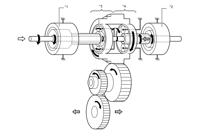
Text in Illustration *1 MG1 *2 MG2 *3 Power Split Planetary Gear Unit *4 Motor Speed Reduction Planetary Gear Unit Rotation Direction From Engine 
From MG2 
To Wheels
-
-
MG2 Motive Force Transmission Path
-
The motive force of MG2 is transmitted via the sun gear and is output to the ring gear in order to drive the wheels. The carrier of the motor speed reduction planetary gear unit is fixed. As a result, the motor speed reduction planetary gear unit reduces the speed of MG2, increasing torque in accordance with a set gear ratio. The direction of rotation of MG2 changes according to whether the vehicle is travelling forward or in reverse.
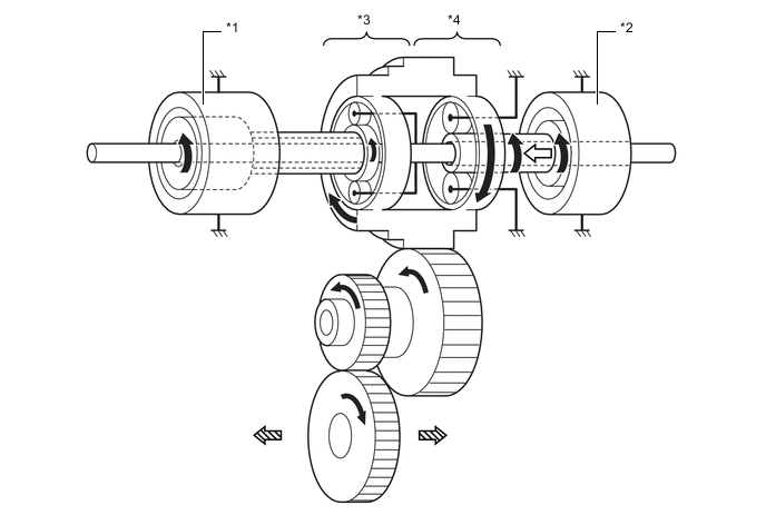
Text in Illustration (Driving Forward:) *1 MG1 *2 MG2 *3 Power Split Planetary Gear Unit *4 Motor Speed Reduction Planetary Gear Unit Rotation Direction From MG2 To Wheel - - 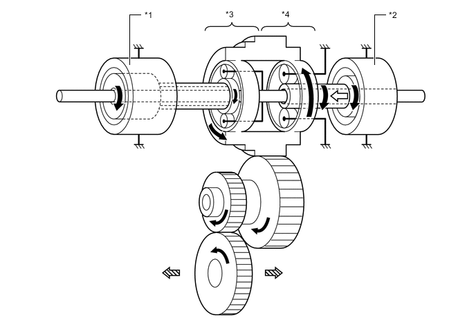
Text in Illustration (Driving in Reverse:) *1 MG1 *2 MG2 *3 Power Split Planetary Gear Unit *4 Motor Speed Reduction Planetary Gear Unit Rotation Direction From MG2 To Wheel - -
-
-
Engine Motive Force Transmission Path
-
The engine motive force, which is input by the carrier, is transmitted to the sun gear. Thus, motive force is transmitted in order to operate MG1 as a generator.

Text in Illustration *1 MG1 *2 MG2 *3 Power Split Planetary Gear Unit *4 Motor Speed Reduction Planetary Gear Unit Rotation Direction From Engine To MG1 - -
-
-
MG1 Motive Force Transmission Path
-
The motive force of MG1 is transmitted via the sun gear and is output to the carrier. Thus, motive force is transmitted in order to start the engine.
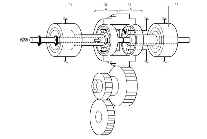
Text in Illustration *1 MG1 *2 MG2 *3 Power Split Planetary Gear Unit *4 Motor Speed Reduction Planetary Gear Unit Rotation Direction From MG1 To Engine - -
-
-