BRAKE CONTROL SYSTEM
-
OUTLINE
-
The brake actuator and the skid control ECU are integrated and a hydraulic brake booster is provided, thus optimizing the hydraulic circuit and offering a weight reduction.
-
The brake control functions (ABS with EBD, Brake Assist, TRC, VSC and Hill-start Assist Control) are provided.
-
An electronically controlled brake system is used to control the hydraulic pressure at the 4 wheels.
-
A regenerative brake cooperative control is used.
-
An emergency brake signal is used. This function automatically flashes the hazard warning lights in 4 Hz cycles during sudden braking, in order to alert vehicles behind and reduce the risk of an accident.
-
-
MAIN FEATURES
-
Electronically Controlled Brake System
-
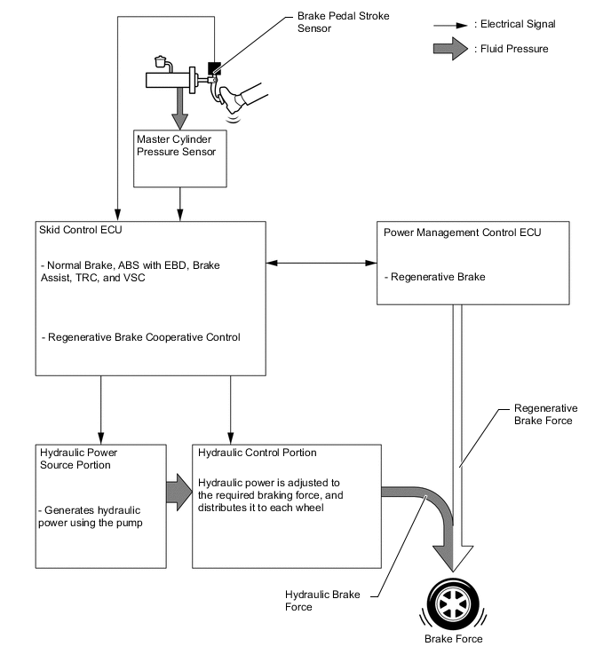
In this system, the conventional brake booster portion has been discontinued. Instead, it consists of hydraulic brake booster, brake actuator and brake booster pump assembly.
-
During normal braking, the fluid pressure generated by the hydraulic brake booster does not directly actuate the wheel cylinders, but serves as a hydraulic pressure signal. Instead, the actual control pressure is obtained by regulating the fluid pressure of the brake booster pump assembly, which actuates the wheel cylinders.
-
When the skid control ECU detects a fault in the system, brake force can be ensured by applying the brake using the fluid pressure boosted by the hydraulic brake booster.
-
-
Regenerative Brake Cooperative Control
-
Regenerative braking consists of a resistance force that is generated at the rotational axle in the reverse direction of the rotation of the generator (MG2) that is generating electricity. The greater the generated amperage (battery charging amperage), the greater will be the resistance force.
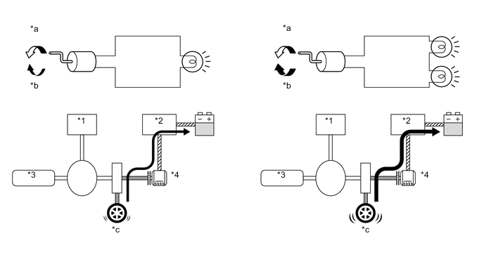
Text in Illustration *1 MG1 *2 Inverter *3 Engine *4 MG2 *a Rotating direction to electricity generation *b Resistance *c Brake Force - - -
The drive wheels and MG2 are joined mechanically. When the drive wheels rotate MG2 and cause it to operate as a generator, a regenerative brake force of MG2 is transmitted to the drive wheels. Based on the signals from the skid control ECU, this force is controlled by the hybrid system, which controls the generation of electricity.
-
The regenerative brake cooperative control does not rely solely on the braking force of the hydraulic brake system to supply the brake force required by the driver. Instead, by effecting cooperative control with the hybrid system, this control provides a joint braking force provided by the regenerative braking and the hydraulic braking. As a result, this control minimizes the loss of the kinetic energy associated with the normal hydraulic braking, and recovers this energy by converting it into electrical energy.
-
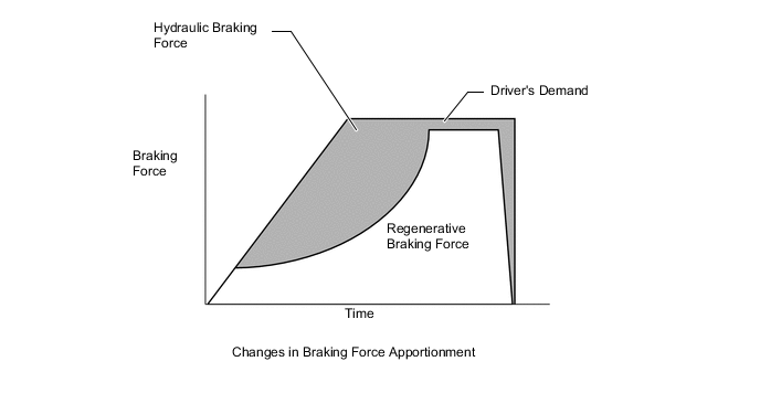
The apportioning of the brake force between the hydraulic braking and the regenerative braking varies by the vehicle speed and time.
-
The apportioning of the brake force between the hydraulic braking and the regenerative braking is accomplished by controlling the hydraulic braking so that the total brake force of the hydraulic braking and the regenerative braking matches the brake force required by the driver.
-
If the regenerative braking becomes inoperative due to a malfunction in the hybrid system, the brake system effects control so that the entire brake force required by the driver is supplied with the hydraulic brake system.
-
-
-
PRECAUTION
-
When brake control system is activated, the brake pedal could shudder, which is a normal occurrence of the system in operation and should not be considered as a malfunction.
-