СИСТЕМА СНИЖЕНИЯ ТОКСИЧНОСТИ ОТРАБОТАВШИХ ГАЗОВ ДЕТАЛЬНОЕ ОПИСАНИЕ
-
FUNCTION OF MAIN COMPONENTS
-
The main components of the exhaust emission control system are as follows:
Component Function TWC Oxidizes CO and HC in the exhaust gas and deoxidizes NOx at the same time, to purify them into CO2, H2O and N2.
Oxygen Sensor The signal of the air fuel ratio sensor changes abruptly between lean and rich at the stoichiometric air fuel ratio. Located downstream of the catalytic converter. Air Fuel Ratio Sensor Is used to determine the concentration of oxygen remaining in the exhaust gas. Has a characteristic where its output is proportional to the engine air fuel ratio. Located upstream of the catalytic converter. ECM Controls the volume of fuel consumed based primarily on the signal from the air fuel ratio sensor, with minor corrections based on the signal from the oxygen sensor. This control optimizes the exhaust emissions. -
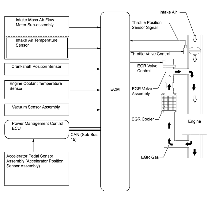
The main components of the EGR system are as follows (Models with EGR System):
Component Function Vacuum Sensor Assembly Detects the pressure in the intake manifold and sends signals to the ECM for EGR control. EGR Valve Assembly Opens and closes based on signals from the ECM and controls the flow rate of the exhaust gas in the EGR bypass. EGR Cooler Assembly The EGR cooler cools the exhaust gas to improve EGR efficiency. Power Management Control ECU Sends signals such as the accelerator pedal position sensor signal to the ECM. ECM Based on the signals received from the sensors, the ECM determines the EGR volume in accordance with the engine operating conditions. -
The main components of the blowby gas ventilation system are as follows:
Component Function PCV Valve (Ventilation Valve Sub-assembly) Opens and closes using vacuum generated in the intake manifold and controls the flow rate of the blowby gas. Oil Separator (Ventilation Case Sub-assembly) Collects oil mist in the blowby gas, reducing the oil consumption. -
The main components of the evaporative emission control system are as follows:
Component Function Charcoal Canister Sub-assembly Contains activated charcoal to adsorb the fuel vapor that is created in the fuel tank assembly. Purge VSV Opens in accordance with the signals from the ECM when the system is purging in order to send the fuel vapor that was adsorbed by the charcoal canister assembly into the intake manifold. ECM Controls the purge VSV in accordance with the signals from various sensor in order to achieve a purge volume that suits the driving conditions.
-
-
SYSTEM CONTROL
-
EGR Control (Models with EGR System)
-
For the EGR system, an amount of EGR gas, which is regulated in accordance with the engine conditions, is allowed to flow into the intake passage, reducing the peak temperature in the engine combustion chamber and achieving low fuel consumption.
-
By sensing the engine driving conditions and the actual amount of the EGR valve assembly opening, the ECM operates the EGR valve assembly and throttle control motor to regulate the amount of exhaust gas that is recirculated.
-
A highly efficient EGR cooler assembly is used to achieve the optimized EGR rate.
-
EGR chambers are provided in the intake manifold so that EGR gas is equally distributed to the cylinders.
-
-
Blowby gas ventilation system
-
By introducing blowby gas into the intake manifold for combustion, the system prevents the blowby gas, which includes a large amount of HC, from being discharged into the atmosphere. The amount of airflow through the crankcase (blowby gas introduction volume) is controlled according to the engine operating conditions. This prevents the excessive consumption of engine oil, and is a factor in idle speed control.
-
This system uses the ventilation method, which sucks the blowby gas directly from the stiffening crankcase assembly, enhancing the ventilation efficiency.
-
An oil separator (ventilation case sub-assembly) is provided in the blowby gas passage inside the cylinder head cover sub-assembly. This separates the engine oil from the blowby gas in order to reduce oil degradation and reduce the amount of engine oil consumed.
-
The Positive Crankcase Ventilation (PCV) valve (ventilation valve sub-assembly) passage returns the blowby gas into the intake manifold in accordance with the intake manifold vacuum.
-
Under light load conditions, the intake manifold vacuum causes the blowby gas to be drawn via the PCV valve into the intake manifold.
-
Under heavy load conditions, the introduction of fresh air is stopped, allowing a large amount of blowby gas to be drawn into the intake system.
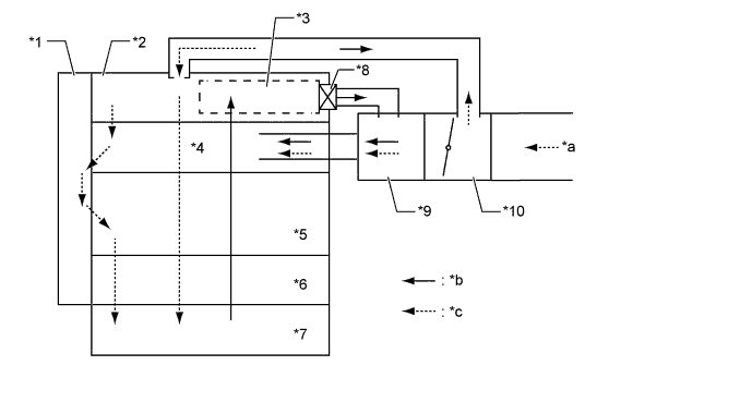
Text in Illustration *1 Timing Chain Cover Assembly *2 Cylinder Head Cover Sub-assembly *3 Oil Separator (Ventilation Case Sub-assembly) *4 Cylinder Head Sub-assembly *5 Cylinder Block Sub-assembly *6 Stiffening Crankcase Assembly *7 Oil Pan Sub-assembly *8 PCV Valve (Ventilation Valve Sub-assembly) *9 Intake Manifold *10 Throttle Body with Motor Assembly *a from Air Cleaner Assembly *b Blowby Gas *c Fresh Air - -
-
-
Evaporative Emission Control
-
When the engine has reached a predetermined state [closed loop, engine coolant temperature above 80°C (176°F), etc.], stored fuel vapor is purged from the charcoal canister sub-assembly whenever the purge VSV is opened by the ECM.
-
The ECM will change the duty ratio cycle of the purge VSV, thus controlling purge flow volume. Purge flow volume is determined by intake manifold pressure and the duty ratio cycle of the purge VSV. Atmospheric pressure is allowed into the charcoal canister sub-assembly to ensure that purge flow is constantly maintained whenever purge vacuum is applied to the charcoal canister sub-assembly.
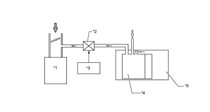
Text in Illustration *1 Engine *2 Purge VSV *3 ECM *4 Charcoal Canister Sub-assembly *5 Fuel Tank Assembly - -
-
-
-
CONSTRUCTION
-
Three-Way Catalyst (TWC)
-
TWCs are provided in the exhaust manifold converter sub-assembly and also in the front exhaust pipe assembly.
-
An exhaust manifold converter sub-assembly with an integrated TWC is used. This realizes quick warm-up of the catalytic converter, helping to reduce emissions immediately after engine start.
-
These TWCs enable improved exhaust emissions through optimized cell density and wall thickness.
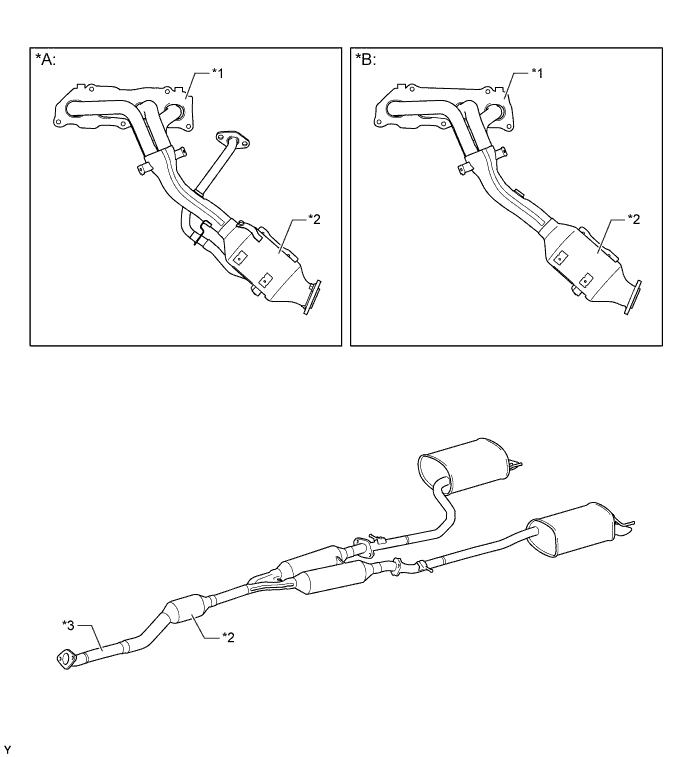
Text in Illustration *A Models with EGR System *B Models without EGR System *1 Exhaust Manifold Converter Sub-assembly *2 TWC *3 Front Exhaust Pipe Assembly - -
-
-
EGR Valve and EGR Cooler
-
A step motor type EGR valve assembly is used to precisely control the EGR gas flow amount.
-
The EGR cooler cools the exhaust gas to improve the EGR efficiency.
-
Stainless steel is used for the EGR cooler assembly in consideration of reliability at high temperatures.
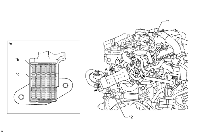
Text in Illustration *1 EGR Valve Assembly *2 EGR Cooler Assembly *a A-A Cross Section *b EGR Gas Passage *c Water Passage - - 
EGR Gas 
Engine Coolant
-
-
Purge VSV
-
The purge VSV controls purge flow volume in accordance with duty signals from the ECM. Purge flow volume is determined by the on/off intervals of the drive signal from the ECM (duty ratio).
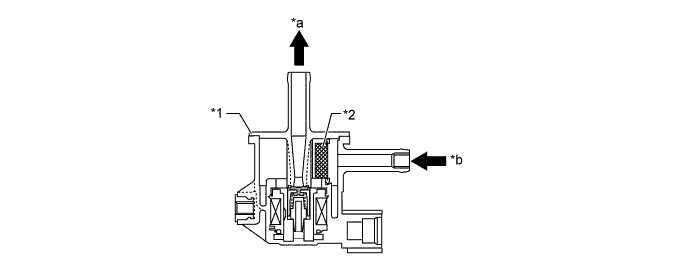
Text in Illustration *1 Vacuum Switching Valve *2 Filter *a to Purge Port *b from Charcoal Canister Sub-assembly
-
-