| *1 |
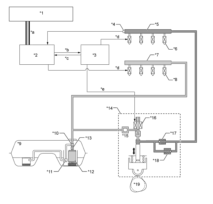
Power Management Control ECU |
*2 |
ECM |
| *3 |
EDU (Injector Driver) |
*4 |
Fuel Pressure Sensor |
| *5 |
Fuel Delivery Pipe Sub-assembly (for Direct Injection) |
*6 |
Fuel Injector Assembly (for Direct Injection) |
| *7 |
Fuel Delivery Pipe Sub-assembly (for Port Injection) |
*8 |
Fuel Injector Assembly (for Port Injection) |
| *9 |
Fuel Tank Assembly |
*10 |
Fuel Pressure Regulator Assembly |
| *11 |
Jet Pump |
*12 |
Fuel Pump Assembly (for Low Pressure) |
| *13 |
Fuel Filter Assembly |
*14 |
Fuel Pump Assembly (for High Pressure) |
| *15 |
Fuel Pressure Pulsation Damper Assembly |
*16 |
Spill Control Valve |
| *17 |
Check Valve (60 kPa) |
*18 |
Fuel Relief Valve (23.6 MPa) |
| *19 |
Intake Camshaft (Cam to Drive Fuel Pump Assembly (for High Pressure)) |
- |
- |
| *a |
CAN (Sub Bus 15) |
*b |
Spill Control Valve Drive Indication Signal |
| *c |
Spill Control Valve Operation Confirmation Signal |
*d |
Injector Drive Signal |
| *e |
Spill Control Valve Drive Signal |
- |
- |