СИСТЕМА SFI ДЕТАЛЬНОЕ ОПИСАНИЕ
-
FUNCTION OF MAIN COMPONENTS
-
The main components of the engine control system are as follows:
Component Outline Quantity Function ECM 32-bit CPU 1 The ECM optimally controls the SFI, ESA and ETCS-i to suit the operating conditions of the engine in accordance with the signals provided by the sensors. Intake Mass Air Flow Meter Sub-assembly Mass Air Flow Meter Hot-wire Type 1 This sensor has a built-in hot-wire to directly detect the intake air mass. Intake Air Temperature Sensor Thermistor Type 1 This sensor detects the intake air temperature by means of an internal thermistor. Engine Coolant Temperature Sensor Thermistor Type 1 This sensor detects the engine coolant temperature by means of an internal thermistor. Fuel Pressure Sensor Semiconductor Type 1 This sensor detects the fuel pressure in the fuel delivery pipe. Crankshaft Position Sensor [No. of Rotor Teeth] Pick-up Coil Type [36 - 2] 1 This sensor detects the engine speed and crankshaft angle. Camshaft Position Sensor (Intake Camshaft) [No. of Rotor Teeth] Magnetic Resistance Element (MRE) Type [3] 1
-
This sensor performs cylinder identification.
-
This sensor is used to detect the intake camshaft position.
Camshaft Position Sensor (Exhaust Camshaft) [No. of Rotor Teeth] Magnetic Resistance Element (MRE) Type [3] 1
-
This sensor performs cylinder identification.
-
This sensor is used to detect the exhaust camshaft position.
Vacuum Sensor Assembly Semiconductor Silicon Chip Type 1 This sensor detects the pressure in the intake manifold and sends signals to the ECM. Throttle Body with Motor Assembly Throttle Position Sensor Linear (Non-contact) Type 1 This sensor detects the throttle valve opening angle. Knock Control Sensor Built-in Piezoelectric Type (Non-resonant Type/Flat Type) 1 This sensor detects an occurrence of engine knocking indirectly through the vibration of the cylinder block. Air Fuel Ratio Sensor Heated Type (Planar Type) 1 As with the oxygen sensor, this sensor detects the oxygen concentration in the exhaust gas. However, it detects the oxygen concentration in the exhaust gas linearly. Oxygen Sensor Heated Type (Cup Type) 1 This sensor detects the oxygen concentration in the exhaust gas by measuring the electromotive force which is generated in the sensor itself. Fuel Injector Assembly For Port Injection 12-hole Type 4 This injector is an electromagnetically-operated nozzle which injects fuel in accordance with signals from the ECM. For Direct Injection High Pressure Single Slit Nozzle Type 4 This injector contains a high-pressure electromagnetically-operated nozzle used to inject fuel directly into the cylinder. EDU (Injector Driver) Built-in DC/DC Converter 1 The EDU converts the signals from the ECM into high-voltage, high-amperage current in order to drive the direct injection injectors. -
-
-
SYSTEM CONTROL
-
The engine control system of the 2AR-FSE engine has the following features:
System Outline Direct Injection 4-stroke Gasoline Engine Superior Version Sequential Multiport Fuel Injection (D-4S SFI) System
-
This is an L-type SFI system. It directly detects the intake air mass with a hot-wire type intake mass air flow meter sub-assembly.
-
The D-4S SFI system is a fuel injection system which combines direct injection injectors and port injection injectors.
-
Based on signals from each sensor, the ECM controls the injection volume and timing of each type of injector (direct and port injection types) in accordance with the engine speed and engine load in order to optimize combustion conditions.
Electronic Spark Advance (ESA)
-
Ignition timing is determined by the ECM based on signals from various sensors. The ECM corrects ignition timing in response to engine knocking.
-
This system selects the optimal ignition timing in accordance with the signals received from the sensors and sends ignition (IGT) signals to the igniters.
Electronic Throttle Control System-intelligent (ETCS-i) Optimally controls the opening angle of the throttle valve in accordance with the accelerator pedal input and the engine and vehicle operating conditions. Variable Valve Timing-intelligent (Dual VVT-i) Controls the intake and exhaust camshafts to the optimal valve timing in accordance with the engine operating conditions. Fuel Pump Control For High Pressure Regulates the fuel pressure within a range of 2.75 MPa to 18 MPa in accordance with driving conditions. For Low Pressure
-
Based on signals from the ECM, the fuel pump control ECU controls the fuel pump assembly.
-
The fuel pump assembly is stopped when any of the Supplemental Restraint System (SRS) airbags are deployed.
Cooling Fan Control The cooling fan ECU steplessly controls the speed of the fans in accordance with the engine coolant temperature, vehicle speed, engine speed, and air conditioning operating conditions. As a result, cooling performance is improved. Air Fuel Ratio Sensor and Oxygen Sensor Heater Control Maintains the temperature of the air fuel ratio sensors or oxygen sensors at an appropriate level to increase the ability of the sensor to accurately detect the concentration of oxygen. Fail-safe When the ECM detects a malfunction, the ECM stops or controls the engine according to the data already stored in memory. Diagnosis When the ECM detects a malfunction, the ECM records the malfunction and related information. -
-
-
FUNCTION
-
Direct Injection 4-stroke Gasoline Engine Superior Version Sequential Multiport Fuel Injection (D-4S SFI) System
-
The D-4S system is a fuel injection system which combines direct injection injectors and port injection injectors.
-
The intake mass air flow meter sub-assembly detects intake air mass to control fuel injection volume.
-
Based on signals from each sensor, the ECM controls the injection volume and timing of each type of fuel injector (direct and port injection types) in accordance with engine load and engine speed in order to optimize combustion conditions.
-
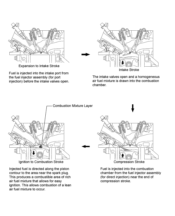
To promote warm-up of the catalyst after a cold engine start, this system uses a stratified air fuel mixture. This creates an area near the spark plug that is richer than the rest of the air fuel mixture. This also allows a greater ignition timing retard to be used, raising the exhaust gas temperature. The increased exhaust gas temperatures promote rapid warm-up of the catalysts, significantly reducing exhaust emissions.
-
When the engine is idling after warm-up, the fuel injector assembly (for port injection) is used to inject fuel, ensuring quietness.
-
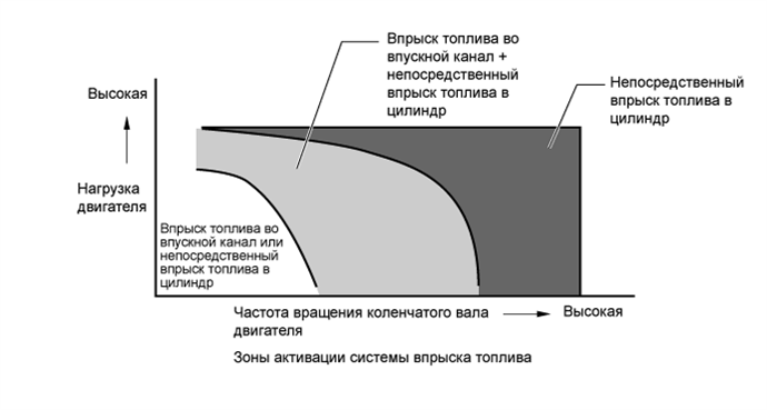
Stratified Combustion: To achieve stratified combustion, immediately after a cold engine start, fuel is injected into the intake port from the fuel injector assembly (for port injection) during the exhaust stroke. Fuel is also injected from the fuel injector assembly (for direct injection) near the end of the compression stroke. This results in an air fuel mixture that is stratified, and the area near the spark plug is richer than the rest of the air fuel mixture. This allows a retarded ignition timing to be used, raising the exhaust gas temperature. The increased exhaust gas temperatures promote rapid warm up of the catalysts, and significantly improve exhaust emission performance.
-
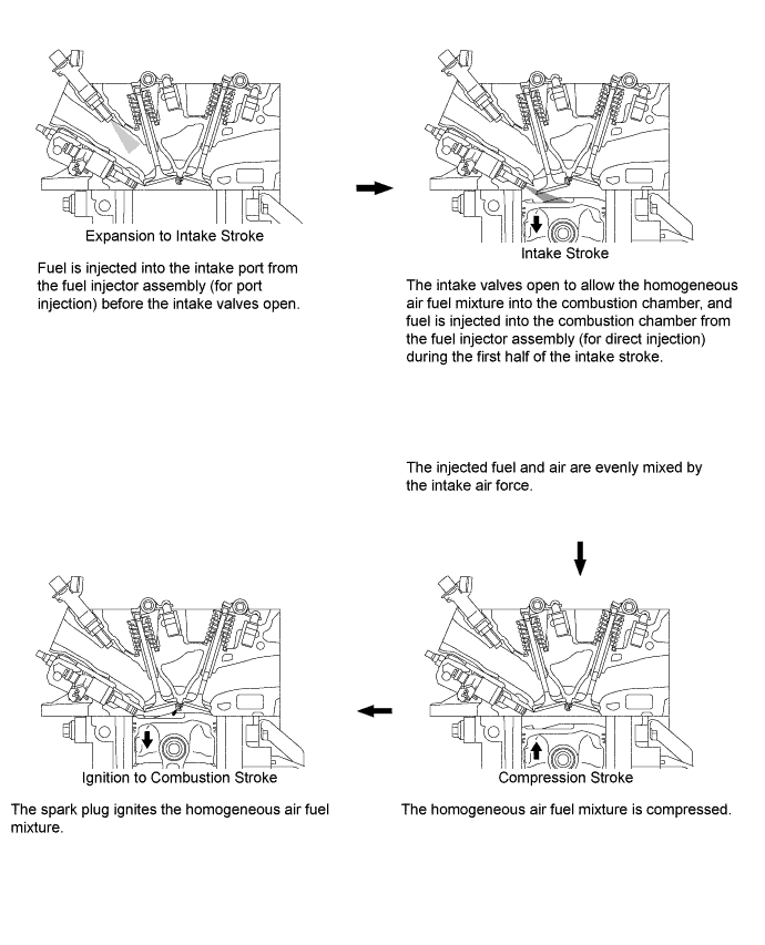
Homogeneous Combustion: To optimize combustion conditions, the ECM controls injection volume and timing of the fuel injector assemblies (for port injection) which inject fuel into the intake ports during the expansion, exhaust, and intake strokes. The ECM also controls the injection volume and timing of the fuel injector assemblies (for direct injection) which inject fuel during the first half of the intake stroke. The homogeneous air fuel mixture is created by either combined or individual use of the 2 different types of injectors. This allows utilization of the evaporation heat of the injected fuel to cool the compressed air, and it also allows an increase of charging efficiency and power output.
-
Air Fuel Ratio Control
-
Fuel injection volume is determined based on the engine speed and the intake air volume. In addition, feedback control is performed for the air-fuel ratio after engine start based on the signal from the air fuel ratio sensor.
Control Combustion State Air/Fuel Ratio Injection Timing* Precondition Lean air-fuel ratio control Stratified Combustion 15 to 16 : 1 Compression Stroke Immediately after cold engine start Stoichiometric air/fuel ratio control Homogeneous Combustion 14 to 15 : 1 Intake Stroke Low to mid-load driving Air/fuel ratio feedback control prohibition Homogeneous Combustion - Intake Stroke High-load driving Cold engine
-
*: Of the fuel injector assembly (for direct injection). The fuel injector assembly (for port injection) performs respective control to inject fuel from the expansion stroke to the intake stroke in accordance with the engine running conditions.
-
-
Fuel Cut
-
When the engine speed exceeds the specified value, fuel injection is stopped to prevent over-revving.
Engine speed for fuel-cut at high revs Engine speed 6400 rpm or more -
-
-
Dual VVT-i System
-
The Dual Variable Valve Timing-intelligent (VVT-i) system is designed to control the intake and exhaust camshafts within a range of 50° and 40° respectively (of crankshaft angle) to provide valve timing that is optimally suited to the engine operating conditions. This improves torque in all speed ranges as well as increasing fuel economy and reducing exhaust emissions.
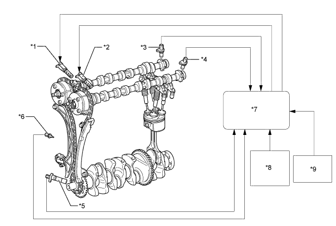
Text in Illustration *1 Camshaft Timing Oil Control Valve Assembly (Intake Side) *2 Camshaft Timing Oil Control Valve Assembly (Exhaust Side) *3 Camshaft Position Sensor (Intake Side) *4 Camshaft Position Sensor (Exhaust Side) *5 Crankshaft Position Sensor *6 Engine Coolant Temperature Sensor *7 ECM *8 Intake Mass Air Flow Meter Sub-assembly
-
Intake Air Temperature Sensor
*9 Throttle Body with Motor Assembly
-
Throttle Position Sensor
- - -
-
-
Electronic Throttle Control System-intelligent (ETCS-i)
-
The ECM performs integrated control to optimally adjust the throttle valve opening angle in accordance with the engine torque command signal from the power management control ECU, realizing smooth driving in any speed range.
-
The throttle body with motor assembly incorporates throttle valve opening angle control (nonlinear control) and idle speed control (ISC).
-
Cooperative control with the powertrain allows for excellent operability and driving comfort.
-
Two CPUs, one for ETCS-i control and one for SFI control, mutually monitor each other, ensuring reliability.
-
The throttle position sensor employs a dual-circuit system to reinforce the fail-safe function, thereby ensuring reliability.
ETCS-i Controls Throttle Valve Opening Angle Control The throttle valve opening angle is controlled to generate engine output in accordance with the vehicle driving conditions and the engine torque command signal from the power management control ECU. Idle Speed Control Controls fast idle speed in accordance with the engine coolant temperature and controls idle speed after the engine has warmed up. Also, controls idle speed using the throttle opening angle in accordance with engine accessory load.
-
-
Fuel Pump Control (for Low Pressure)
-
The fuel pump assembly is controlled by the fuel pump control ECU based on signals from the ECM. The fuel pump control has a fuel cut control. The fuel cut control stops the fuel pump assembly when any of the Supplemental Restraint System (SRS) airbags have deployed.
-
-
Cooling Fan Control
-
The cooling fan control system achieves an optimal fan speed in accordance with the engine coolant temperature, vehicle speed, engine speed, and air conditioning operating conditions.
-
-
-
CONSTRUCTION
-
Intake Mass Air Flow Meter Sub-assembly
-
The intake mass air flow meter sub-assembly, which is a slot-in type, allows a portion of the intake air to flow through the detection area. By directly measuring the mass and the flow rate of the intake air, the detection precision is improved and the intake air resistance is reduced.
-
This intake mass air flow meter sub-assembly has a built-in intake air temperature sensor.
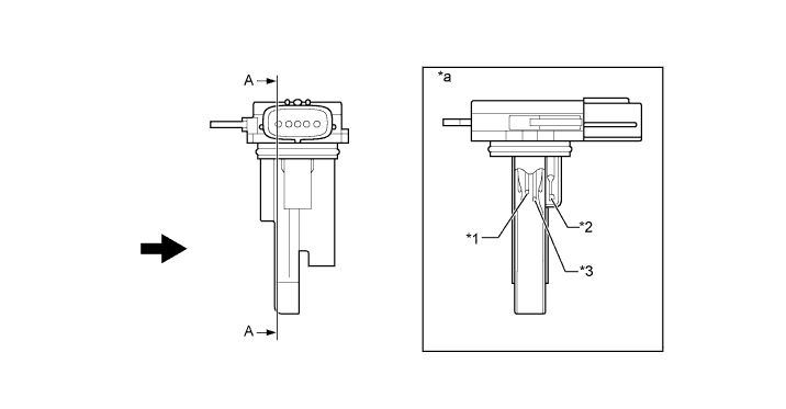
Text in Illustration *1 Platinum Hot-wire Element *2 Intake Air Temperature Sensor *3 Temperature Sensing Element - - *a A - A Cross Section - - 
Air Flow - -
-
-
Vacuum Sensor
-
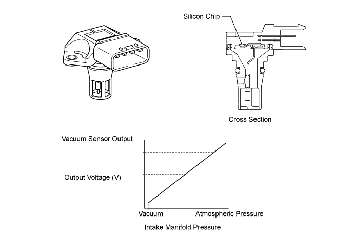
The vacuum sensor assembly detects pressure inside the intake manifold as an absolute pressure with a built-in sensor and outputs a voltage. Based on the voltage from the vacuum sensor assembly, the ECM controls the air fuel ratio and EGR*.
-
*: Models with EGR system
-
-
The vacuum sensor assembly consists of a silicon chip which changes its electrical resistance when pressure is applied to it. The sensor converts the pressure into an electrical signal, and sends the electrical signal to the ECM in an amplified form.
-
-
Crankshaft Position Sensor
-
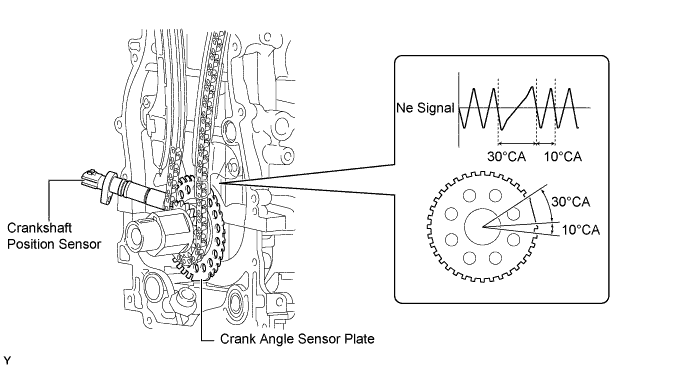
A pick-up type crankshaft position sensor is used to detect the engine speed and crankshaft angle.
-
The crank angle sensor plate (timing rotor) of the crankshaft consists of 34 teeth with 2 teeth missing. The crankshaft position sensor outputs the crankshaft rotation signals every 10°, and the change of the signal due to the missing teeth is used to determine top-dead-center.
-
-
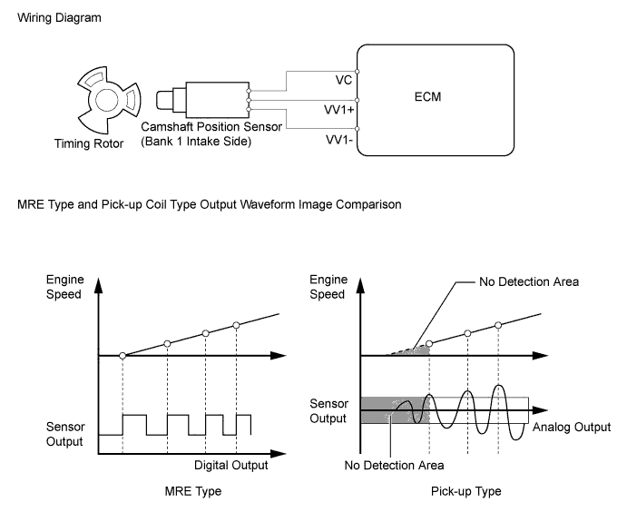
Camshaft Position Sensor
-
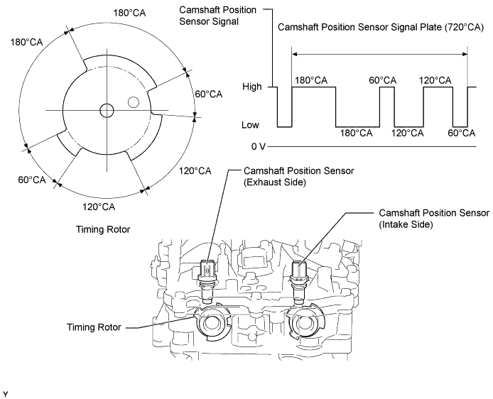
Magnetic Resistance Element (MRE) type camshaft position sensors (intake and exhaust) are used. To detect each camshaft position, a timing rotor that is secured to the camshaft is used to generate 6 (3 high output, 3 low output) pulses for every 2 revolutions of the crankshaft. The timing rotor for each camshaft is part of the respective camshaft.
-
An MRE type camshaft position sensor consists of an MRE, a magnet and a sensor. The direction of the magnetic field changes due to the profile (protruding and non-protruding portions) of the timing rotor, which passes by the sensor. As a result, the resistance of the MRE changes, and the output voltage to the ECM changes to high or low. The ECM detects the camshaft position based on this output voltage.
-
-
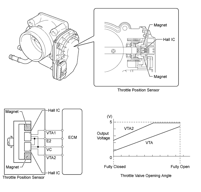
Throttle Position Sensor
-
This non-contact type throttle position sensor uses a Hall IC, which is mounted on the throttle body with motor assembly.
-
The Hall IC is surrounded by a magnetic yoke. The Hall IC converts the changes that occur in the magnetic flux into electrical signals, and outputs them in the form of throttle valve position signals to the ECM.
-
The Hall IC contains circuits for the main and sub signals. It converts the throttle valve opening angle into electric signals that have differing characteristics, and outputs them to the ECM.
-
-
Knock Control Sensor (Flat Type)
-
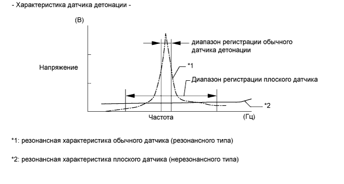
In a conventional knock control sensor (resonant type), a vibration plate is built into the sensor. This plate has the same resonance point as the knocking* frequency of the engine block. This sensor can only detect vibration in this frequency band.
-
*: The term "knock" or "knocking" is used in this case to describe either preignition or detonation of the air fuel mixture in the combustion chamber. This preignition or detonation refers to the air fuel mixture being ignited earlier than is advantageous. This use of "knock" or "knocking" is not primarily used to refer to a loud mechanical noise that may be produced by an engine.
-
-
A flat type knock control sensor (non-resonant type) has the ability to detect vibration in a wider frequency band (from about 5 kHz to 15 kHz). It has the following features:
-
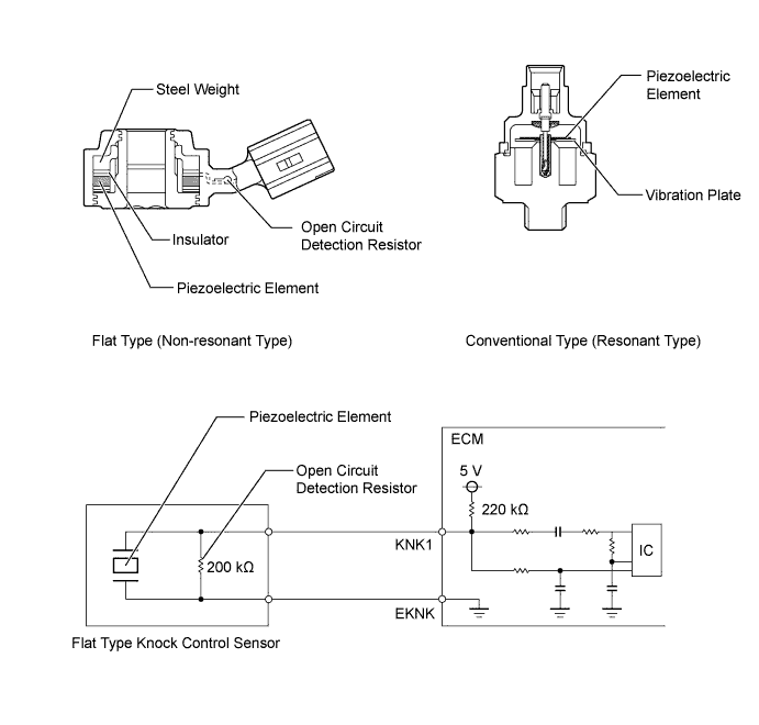
A flat type knock control sensor is installed to an engine by placing it over a stud bolt installed on the cylinder block sub-assembly. For this reason, a hole for the stud bolt exists in the center of the sensor.
-
In the sensor, a steel weight is located in the upper portion. An insulator is located between the weight and a piezoelectric element.
-
An open/short circuit detection resistor is integrated in the sensor.
-
-
The engine knocking frequency will vary slightly depending on the engine speed. The flat type knock control sensor can detect vibration even when the engine knocking frequency changes. Due to the use of the flat type knock control sensor, the vibration detection ability is increased compared to a conventional type knock control sensor, and more precise ignition timing control is possible.
-
An open or short circuit detection resistor is integrated in the sensor. When the ignition is ON, the open circuit detection resistor in the knock control sensor and the resistor in the ECM keep the voltage at terminal KNK1 constant. An Integrated Circuit (IC) in the ECM constantly monitors the voltage of terminal KNK1. If an open or short circuit occurs between the knock control sensor and the ECM, the voltage of terminal KNK1 will change and the ECM will detect this change and store a Diagnostic Trouble Code (DTC).
-
Vibrations caused by knocking are transmitted to the steel weight. The inertia of this weight applies pressure to the piezoelectric element. This action generates electromotive force.
Text in Illustration *1 Steel Weight *2 Piezoelectric Element *a Inertia - -
-
-
Air Fuel Ratio Sensor and Oxygen Sensor
-
A planar type air fuel ratio sensor is used.
-
The planar type air fuel ratio sensor uses alumina, which excels in heat conductivity and electrical insulation, to integrate a sensor element with a heater, thus improving the warm-up performance of the sensor.
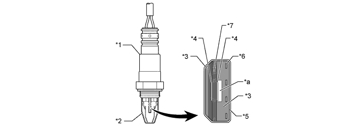
Text in Illustration *1 Air Fuel Ratio Sensor (Planar Type) *2 Cover *3 Alumina *4 Platinum Electrode *5 Coating (Ceramic) *6 Heater *7 Sensor Element (Zirconia) - - *a Atmosphere - - -
The cup type oxygen sensor contains a sensor element that surrounds a heater.
-
The oxygen sensor is located behind the Three-Way Catalyst (TWC). The output voltage of the oxygen sensor changes in accordance with the oxygen concentration in the exhaust gas. The ECM uses this output voltage to determine whether the present air fuel ratio is richer or leaner than the stoichiometric air fuel ratio.
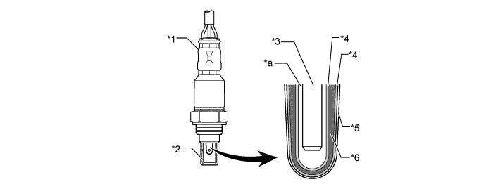
Text in Illustration *1 Oxygen Sensor (Cup Type) *2 Cover *3 Heater *4 Platinum Electrode *5 Coating (Ceramic) *6 Sensor Element (Zirconia) *a Atmosphere - - -
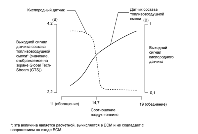
As illustrated below, a conventional oxygen sensor is characterized by a sudden change in its output voltage at the threshold of the stoichiometric air fuel ratio (14.7:1). In contrast, the air fuel ratio sensor data is approximately proportionate to the existing air fuel ratio. The air fuel ratio sensor converts the oxygen density to a current and sends it to the ECM. As a result, the detection precision of the air fuel ratio has been improved. The air fuel ratio sensor data can be viewed using the Global TechStream (GTS).
-
-
Camshaft Timing Oil Control Valve Assembly
-
The camshaft timing oil control valve assembly controls its spool valve using duty-cycle control from the ECM. This allows hydraulic pressure to be applied to the camshaft timing gear assembly or camshaft timing exhaust gear assembly advance or retard side. When the engine is stopped, the camshaft timing oil control valve assembly (intake) will move to the retard position, and the camshaft timing oil control valve assembly (exhaust) will move to the advance position.
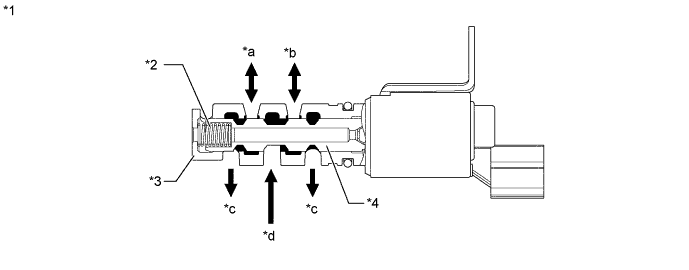
Text in Illustration *1 Camshaft Timing Oil Control Valve Assembly (Intake) *2 Spring *3 Sleeve *4 Spool Valve *a to Camshaft Timing Gear Assembly (VVT-i Controller) (Advance Side)* *b to Camshaft Timing Gear Assembly (VVT-i Controller) (Retard Side)* *c Drain *d Oil Pressure (from Oil Pump)
-
*: On the camshaft timing oil control valve assembly (exhaust), the advance and retard sides are reversed.
-
-
-
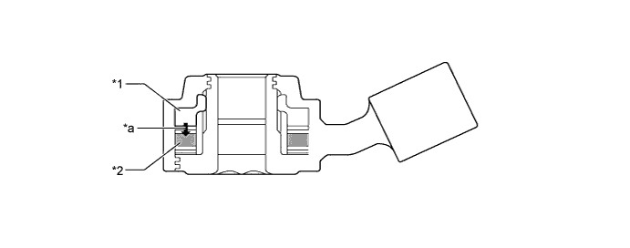
Ignition Coil Assembly
-
The Direct Ignition System (DIS) provides 4 ignition coil assemblies, one for each cylinder. The spark plug caps, which provide contact to the spark plugs, are integrated with the ignition coil assembly. Also, an igniter is enclosed to simplify the system.
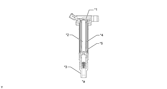
Text in Illustration *1 Igniter *2 Iron Core *3 Plug Cap *4 Secondary Coil *5 Primary Coil - - *a Cross Section - -
-
-
Spark Plug
-
Long-reach type spark plugs are used. This type of spark plug allows the area of the cylinder head sub-assembly that receives the spark plugs to be made thicker. Thus, the cylinder head water jacket can be extended near the combustion chamber, which contributes to cooling performance.
-
The triple ground electrode type iridium-tipped spark plugs are used to achieve a 100000 km (62140 miles) maintenance interval. By making the center electrode out of iridium, it is possible to achieve superior ignition performance and durability when compared to platinum-tipped spark plugs. Furthermore, two ground electrodes have been added to further enhance ignitability, wear resistance, and fouling resistance.
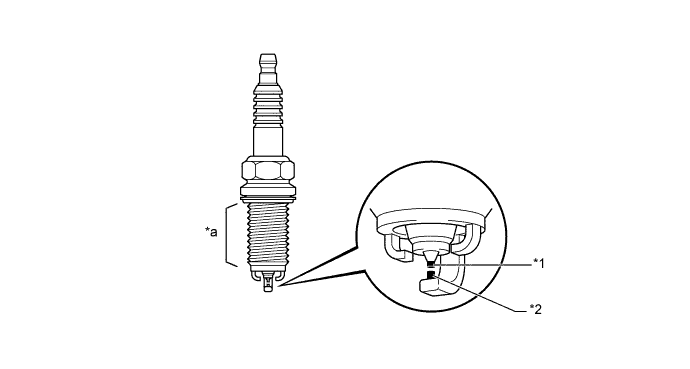
Text in Illustration *1 Iridium Tip *2 Platinum Tip *a Long-reach - -
-
-
-
OPERATION
-
Dual VVT-i System
-
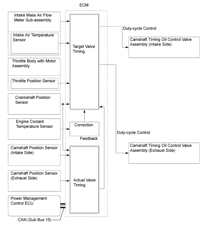
Based on engine speed, intake air volume, throttle position and engine coolant temperature, the ECM calculates optimal valve timing for all driving conditions. The ECM also controls the camshaft timing oil control valve assemblies. In addition, the ECM uses signals from the camshaft position sensors and the crankshaft position sensor to detect the actual valve timing, thus providing feedback control to achieve the target valve timing.
-
When the camshaft timing oil control valve assembly is positioned as illustrated below by the advance signals from the ECM, the resultant oil pressure is applied to the timing advance side vane chamber to rotate the camshaft in the timing advance direction.
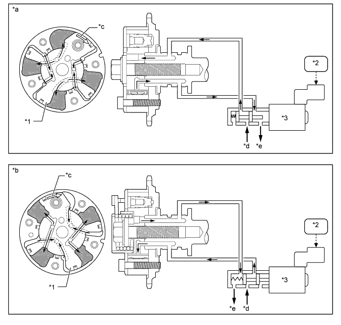
Text in Illustration *1 Vane *2 ECM *3 Camshaft Timing Oil Control Valve Assembly - - *a Advance Side Operation (Intake Side) *b Advance Side Operation (Exhaust Side) *c Rotation Direction *d Oil Pressure *e Drain - - -
When the camshaft timing oil control valve assembly is positioned as illustrated below by the retard signals from the ECM, the resultant oil pressure is applied to the timing retard side vane chamber to rotate the camshaft in the timing retard direction.
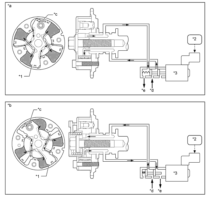
Text in Illustration *1 Vane *2 ECM *3 Camshaft Timing Oil Control Valve Assembly - - *a Retard Side Operation (Intake Side) *b Retard Side Operation (Exhaust Side) *c Rotation Direction *d Oil Pressure *e Drain - - -
After reaching the target timing, the engine valve timing is maintained by keeping the camshaft timing oil control valve assembly in the neutral position unless the engine operating conditions change. This maintains the engine valve timing at the desired target position by preventing the engine oil from running out of the camshaft timing oil control valve assembly.
-
-
Fuel Pump Control (for Low Pressure)
-
In this vehicle, there are 2 types of fuel pump controls. The fuel pump assembly is controlled to an optimum speed to match the engine operating conditions, and the fuel pump assembly operation is stopped when the SRS airbags deploy.
-
The ECM transmits a fuel pump operation request signal to the fuel pump control ECU that corresponds to the engine operating conditions. The fuel pump control ECU receives this request signal and controls the speed of the fuel pump assembly. As a result, under light engine loads, fuel pump assembly speed is kept low to reduce electric power loss.
-
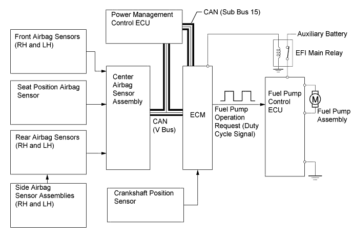
A fuel cut control is used to stop the fuel pump assembly when any of the SRS airbags deploy. In this control, if an airbag deployment signal from the center airbag sensor assembly is detected by the ECM, the ECM will turn off the circuit opening relay. As a result, the power supply to the fuel pump control ECU is stopped, causing the fuel pump assembly to stop operating. After the fuel cut control has been activated, turning the power switch from off to on (IG) cancels the fuel cut control, and the engine can be restarted.
-
The fuel pump control ECU controls fuel pump assembly speed by receiving a duty cycle signal (FPC terminal input) from the ECM.
-
-
Cooling Fan Control
-
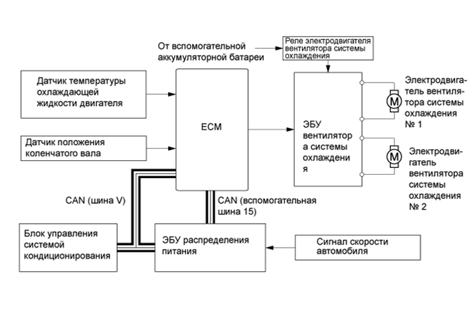
The ECM calculates the cooling fan speed in accordance with the engine coolant temperature, vehicle speed, engine speed and air conditioning operating conditions, and sends the signals to the cooling fan ECU. Upon receiving the signals from the ECM, the cooling fan ECU actuates the cooling fan motor.
-
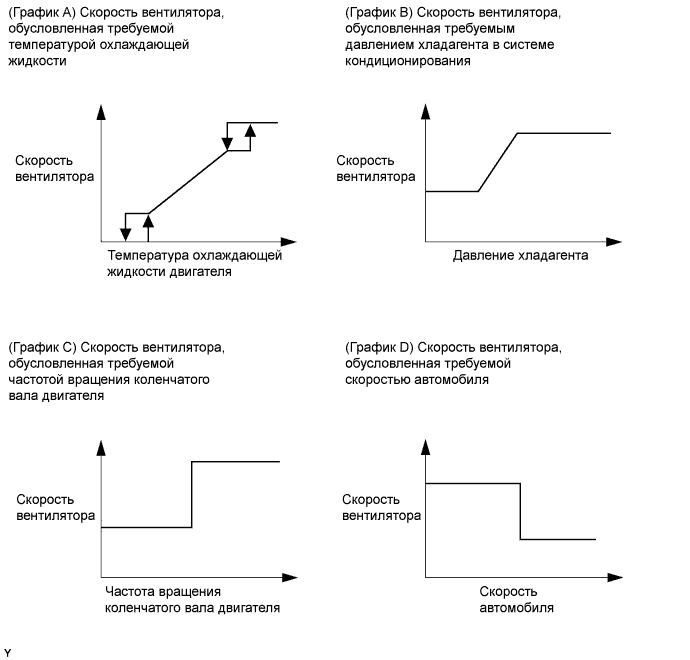
As illustrated below, the ECM determines the required fan speed by selecting the fastest fan speed from among the following:
-
The graphs below show the fan speed required by the engine coolant temperature (Graph A), the fan speed required by the air conditioning refrigerant pressure (Graph B), the fan speed required by the engine speed (Graph C), and the fan speed required by the vehicle speed (Graph D).
-
-