СИСТЕМА SFI РАСПОЛОЖЕНИЕ ДЕТАЛЕЙ
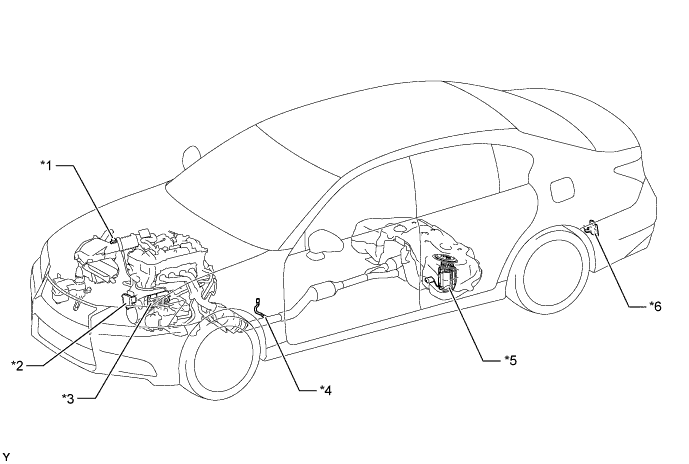
| *1 | Intake Mass Air Flow Meter Sub-assembly
|
*2 | Cooling Fan ECU |
| *3 | ECM | *4 | Oxygen Sensor |
| *5 | Fuel Suction Tube with Pump and Gauge Assembly
|
*6 | Fuel Pump Control ECU |
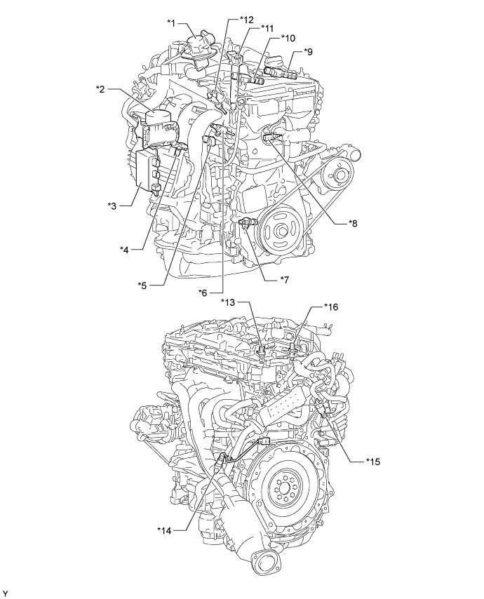
| *1 | Fuel Pump Assembly (for High Pressure) | *2 | Throttle Body with Motor Assembly
|
| *3 | EDU (Injector Driver) | *4 | Vacuum Sensor Assembly |
| *5 | Knock Control Sensor | *6 | Fuel Injector Assembly (for Direct Injection) |
| *7 | Crankshaft Position Sensor | *8 | Engine Coolant Temperature Sensor |
| *9 | Camshaft Timing Oil Control Valve Assembly (Exhaust Side) | *10 | Camshaft Timing Oil Control Valve Assembly (Intake Side) |
| *11 | Ignition Coil Assembly | *12 | Fuel Injector Assembly (for Port Injection) |
| *13 | Camshaft Position Sensor (Exhaust Side) | *14 | Air Fuel Ratio Sensor |
| *15 | Fuel Pressure Sensor | *16 | Camshaft Position Sensor (Intake Side) |
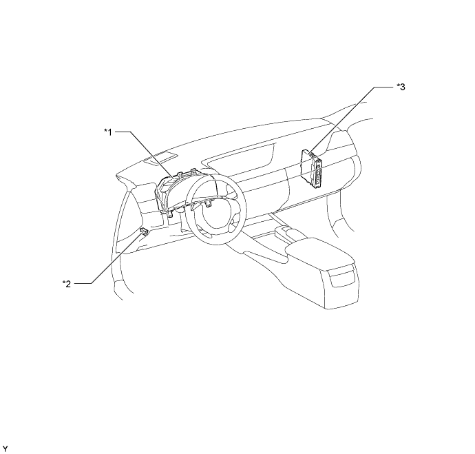
| *1 | Combination Meter Assembly
|
*2 | DLC3 |
| *3 | Power Management Control ECU | - | - |
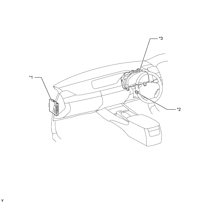
| *1 | Power Management Control ECU | *2 | DLC3 |
| *3 | Combination Meter Assembly
|
- | - |