AUDIO AND VISUAL SYSTEM PARTS LOCATION
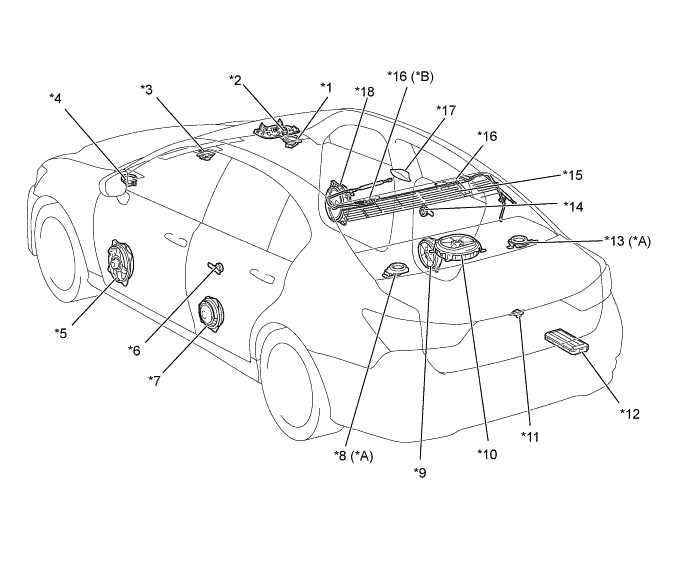
| *A | Models with 17-speaker System | *B | Models with Digital Audio Broadcast (DAB) Antenna |
| *1 | Front No. 2 Speaker Assembly RH | *2 | Map Light Assembly - Telephone Microphone Assembly |
| *3 | Front No. 3 Speaker Assembly | *4 | Front No. 2 Speaker Assembly LH |
| *5 | Front No. 1 Speaker Assembly LH | *6 | Rear No. 2 Speaker Assembly LH |
| *7 | Rear Speaker Assembly LH | *8 | Rear Header Speaker Assembly LH |
| *9 | Rear Speaker Assembly RH | *10 | Rear No. 3 Speaker Assembly |
| *11 | Rear Television Camera Assembly | *12 | Stereo Component Amplifier Assembly |
| *13 | Rear Header Speaker Assembly RH | *14 | Rear No. 2 Speaker Assembly RH |
| *15 | Window Glass Antenna Wire | *16 | Amplifier Antenna Assembly |
| *17 | Telephone Antenna Assembly | *18 | Front No. 1 Speaker Assembly RH |
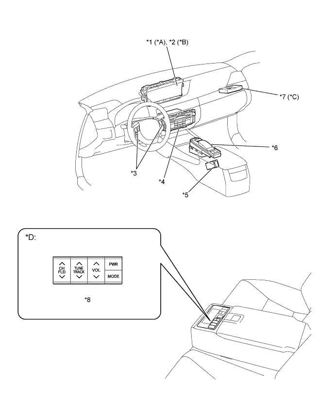
| *A | Models with 8-inch Display | *B | Models with 12.3-inch Display |
| *C | Models with Telematics Transceiver (DCM) | *D | Models with Cooler Control Switch Panel |
| *1 | Multi-display | *2 | Accessory Meter Assembly |
| *3 | Steering Pad Switch Assembly | *4 | Multi-media Module Receiver Assembly |
| *5 | Stereo Jack Adapter Assembly | *6 | Remote Touch |
| *7 | Telematics Transceiver (DCM) | *8 | Cooler Control Switch Panel (Audio Switch) |