BRAKE CONTROL SYSTEM DETAILS
-
FUNCTION OF MAIN COMPONENTS
Component Function Combination Meter Assembly Brake System Warning Light (Red Indicator)
-
Illuminates to alert the driver that the skid control ECU assembly detects the malfunction in the apportioning of the brake force.
-
Illuminates to inform the driver when the parking brake is on or the brake fluid is low.
Brake System Warning Light (Yellow Indicator) Illuminates to alert the driver that a minor malfunction which does not affect the braking force has occurred in the brake system. ABS Warning Light Illuminates to alert the driver when the skid control ECU assembly detects a malfunction in the ABS. Slip Indicator Light
-
Blinks to inform the driver when the TRC, VSC or ABS is operational.
-
Illuminates to alert the driver when the skid control ECU assembly detects a malfunction in the TRC or VSC.
VSC OFF Indicator Light Illuminates to inform the driver when VSC OFF mode is selected. Brake Hold Indicator Light (Yellow Indicator)
-
Illuminates to inform the driver that the brake hold function is operating.
-
Blinks to alert the driver when the skid control ECU assembly detects a malfunction in the brake hold function..
Brake Hold Indicator Light (Green Indicator) Illuminates to inform the driver that the brake hold standby condition has been established. Master Warning Light Illuminates when the warning message is displayed in the multi-information display. Multi-information Display
-
Displays the information message when TRC OFF mode is selected.
-
Displays the warning message when the skid control ECU assembly detects a malfunction in the ABS or EBD.
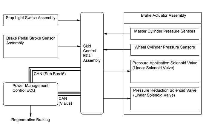
Skid Control Buzzer Assembly Sounds continuously to inform the driver if there is a hydraulic pressure malfunction or power supply failure. Stop Light Switch Assembly Detects the brake pedal depressing signal. Brake Pedal Stroke Sensor Assembly Directly detects the extent of the brake pedal stroke operated by the driver. VSC OFF Switch Enables the driver to select "Normal Mode", "TRC OFF Mode", or "VSC OFF Mode". Brake Hold Switch Switches the brake hold function on and off. Front Door Courtesy Light Switch Assembly (Driver Side) Detects whether the door is open or closed, sends the information to the skid control ECU assembly and activates the electrically controlled brake system when the door is opened while the power switch (push start switch) is off. Speed Sensor Detects the wheel speed of each of the 4 wheels. Yawrate Sensor
-
Detects the vehicle's longitudinal and lateral acceleration.
-
Detects the vehicle's yaw rate.
Steering Sensor Detects the direction and angle of the steering wheel. Brake Master Cylinder Sub-assembly
- Brake Stroke Simulator Cylinder Sub-assembly
Provides a pedal stroke during braking in accordance with the driver's pedal effort. Brake Control Power Supply Assembly
-
An auxiliary power supply to provide stable electrical power to the brake system.
-
When the voltage of the auxiliary battery is low, the brake control power supply assembly supplements the supply of power to the brake system by providing the electric charge that is stored in the unit.
Brake Actuator Assembly Controls the wheel cylinder pressure of each wheel according to a signal from the skid control ECU assembly. Skid Control ECU Assembly Monitors the driving conditions of the vehicle in accordance with the signals received from the sensors, and through cooperative control with each ECU, calculates the required amount of braking force, and controls the brake actuator assembly. Parking Brake ECU Assembly
-
Sends the electric parking brake condition to the skid control ECU assembly.
-
Controls the parking brake with bracket actuator assembly based on the signals received from the skid control ECU assembly.
Power Steering ECU Assembly Controls the steering assist torque based on the signals received from the skid control ECU assembly. Front Steering Control ECU (Models with LDH System)
-
Controls the turning angle of the front wheels based on the signals received from the skid control ECU assembly.
-
Calculates the turning angle of the rear wheels and sends it to the rear steering control ECU.
Rear Steering Control ECU (Model with LDH System) Controls the turning angle of the rear wheels based on the signals received from the front steering control ECU. Absorber Control ECU (Models with AVS) Controls the damping force based on the signals received from the skid control ECU assembly. Driving Support ECU Assembly (Models with Pre-crash Safety System) Makes a request for brake control to the skid control ECU assembly. Power Management Control ECU
-
Actuates regenerative braking upon receiving a signal from the skid control ECU assembly.
-
Sends the actual regenerative braking control value to the skid control ECU assembly.
-
Controls the drive force based on an output control request signal received from the skid control ECU assembly while the VSC or TRC is operating.
-
-
OPERATING CONDITION
-
Brake Hold Function
-
Brake Hold Function Standby Condition
-
To operate the brake hold function, it is first necessary to establish the brake hold standby condition. The brake hold standby condition becomes established when the driver presses the brake hold switch after all the conditions listed below have been met. As a result, the brake hold indicator light (green indicator) illuminates in the combination meter.
Brake Hold Function Standby Conditions
-
Hybrid control system, electric parking brake system and electronically controlled brake system are all operating normally.
-
Driver door is closed.
-
Driver seat belt is buckled.
-
Engine hood is closed.
-
Luggage compartment door is closed.
-
-
-
Brake Hold Function Operation Condition
-
When all of the conditions listed below are met while the brake hold standby condition is established, the brake hold function will operate. When the brake hold function operates, the brake hold indicator light (yellow indicator) will illuminate in the combination meter.
Brake Hold Function Operation Conditions
-
Shift lever is in a position other than P or R.
-
Driver depresses the brake pedal and the vehicle is stopped.
-
Driver is not depressing the accelerator pedal.
-
Vehicle is not on a steep gradient.*
Tech Tips
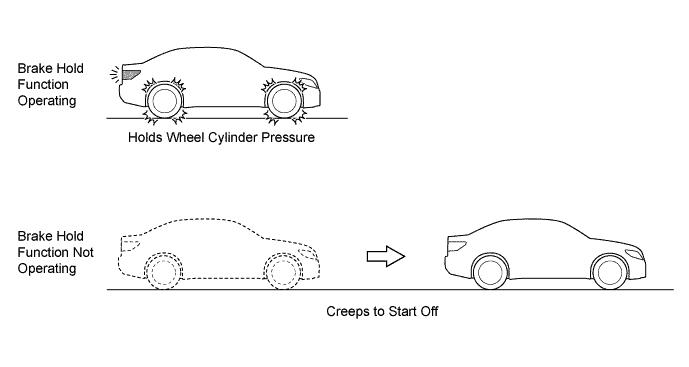
*: If the brake hold function is inoperative because the vehicle is on a steep gradient, the system informs the driver by turning off the brake hold indicator light (yellow indicator) and outputting a warning message on the multi-information display. To support the start-off of the vehicle on a steep uphill gradient, the skid control ECU assembly holds the wheel cylinder pressure for approximately 2 seconds after the driver has released the brake pedal.
-
-
-
Brake Hold Function Operation Ending Condition
-
When one of the conditions listed below has been established, the skid control ECU assembly ends the brake hold function. In addition, it informs the driver that the brake hold function has ended by turning off the brake hold indicator light (yellow indicator).
Brake Hold Function Operation Ending Conditions
-
Driver presses the accelerator pedal.
-
Shift lever is in P.
-
Driver moves the shift lever to R while depressing the brake pedal.
-
-
-
Electric Parking Brake Operation Condition
-
If any one of the conditions listed below is established while the brake hold function is operating and the driver is not depressing the brake pedal, the electric parking brake will lock automatically. At this time, the parking brake will not be canceled even though the accelerator pedal is depressed when starting off the vehicle. Therefore, cancel the parking brake by operating the electric parking brake switch assembly (manual switch) or the shift lever before starting off.
Electric Parking Brake Operation Conditions
-
Driver door is open.
-
Driver seat belt is unbuckled.*
-
Engine hood is open.
-
Luggage compartment door is open.
-
3 minutes have elapsed since the brake hold function operated.*
Tech Tips
*: At this moment, an operation advice message is shown on the multi-information display in the combination meter. By operating in accordance with this message, the electric parking brake does not operate and the brake hold function continues.
-
-
-
Brake Hold Function Standby Condition Canceling Condition
-
If any one of the conditions listed below occurs while the brake hold standby condition is established, the skid control ECU assembly cancels the brake hold standby condition.
Brake Hold Function Standby Condition Canceling Conditions
-
The electric parking brake has locked automatically as a result of the driver seat belt being unbuckled or the driver door, the luggage compartment door or opening the engine hood being opened.
-
Any one of the following takes place while the vehicle is being driven: the driver seat belt is unbuckled or the driver door, luggage compartment door or engine hood is opened..
-
Driver presses the brake hold switch while the brake hold function is inoperative.
-
Driver presses the brake hold switch while depressing the brake pedal and the brake hold function is operating.
-
-
-
Brake Hold Function Operation Prohibition Condition
-
If any system malfunction listed below occurs, the skid control ECU assembly prohibits the operation of the brake hold function. At this time, the skid control ECU assembly alerts the driver by flashing the brake hold indicator light (yellow indicator).
Brake Hold Function Operation Prohibition Conditions
-
Hybrid control system malfunction
-
Electric parking brake system malfunction
-
Electronically controlled brake system malfunction*
Tech Tips
*: When the wheel cylinder pressure cannot be maintained while the brake hold function is operating, the electric parking brake system operates automatically to lock the parking brake. When starting off the vehicle, cancel the parking brake by operating the electric parking brake switch assembly (manual switch) or the shift lever before starting off.
-
-
-
-
-
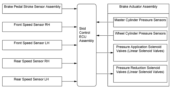
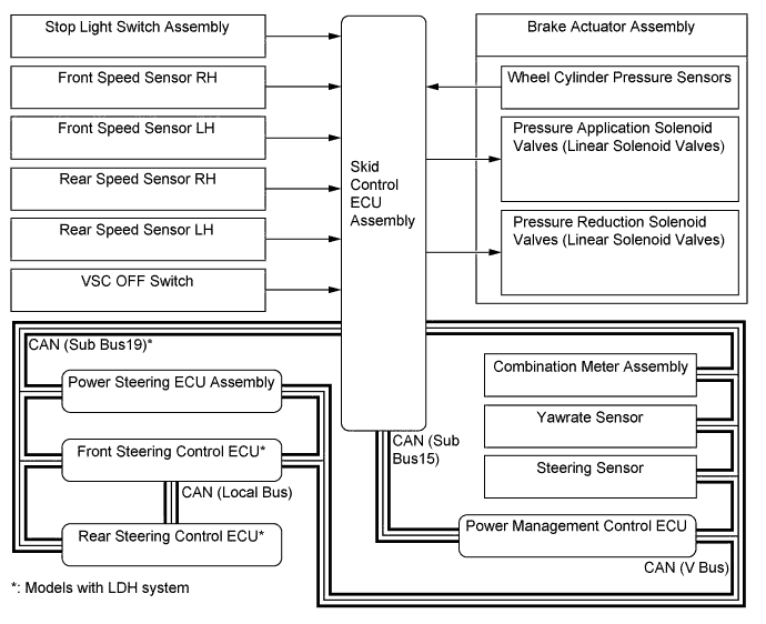
SYSTEM CONTROL
Control Function Electronically Controlled Brake System The electronically controlled brake system detects the amount that the brake pedal is depressed based on signals from the brake pedal stroke sensor. The system uses the skid control ECU assembly to adjust the pressure supplied from the hydraulic pressure source for each wheel, generating optimal braking force. Regenerative Braking Cooperative Control This control performs cooperative control with regenerative braking that is specific to hybrid vehicles to efficiently charge the HV battery. Anti-lock Brake System (ABS) The ABS helps prevent the wheels from locking when the brakes are applied firmly or when braking on a slippery surface. Electronic Brake Force Distribution (EBD) The EBD utilizes ABS, achieving proper brake force distribution between the front and rear wheels in accordance with the driving conditions. In addition, during braking while cornering, the EBD also controls the brake forces of the right and left wheels, helping maintain vehicle behavior. Brake Assist The primary purpose of brake assist is to provide an auxiliary brake force to assist a driver who cannot generate a large brake force during emergency braking, thus helping ensure the vehicle's braking performance. Traction Control (TRC) The TRC helps restrain the slippage of the drive wheels if the driver depresses the accelerator pedal excessively when starting off or while accelerating on a slippery surface. Vehicle Stability Control (VSC) The VSC helps restrain sideways slippage of the vehicle during a strong front wheel skid or strong rear wheel skid, which may occur while cornering. Steering Cooperative Control The steering cooperative control effects cooperative control with the power steering ECU assembly, front steering control ECU* and rear steering control ECU* in order to provide steering assist in accordance with the operating conditions of the vehicle. Brake Hold Function As the driver depresses the brake pedal and the vehicle comes to a stop, this function maintains the hydraulic pressure of the 4 wheels in order to keep the vehicle stopped.
-
*: Models with LDH system
-
Anti-lock Brake System (ABS)
-
The ABS prevents the wheels from locking during sudden braking or braking on a slippery surface. This provides the proper braking force when the vehicle slips, thus ensuring vehicle stability and excellent braking performance.
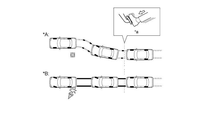
Text in Illustration (Illustration Provides Conceptual Image) *A Models with ABS *B Models without ABS *a Brake Operation - -
-
-
Electronic Brake Force Distribution (EBD)
-
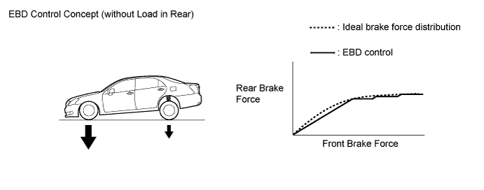
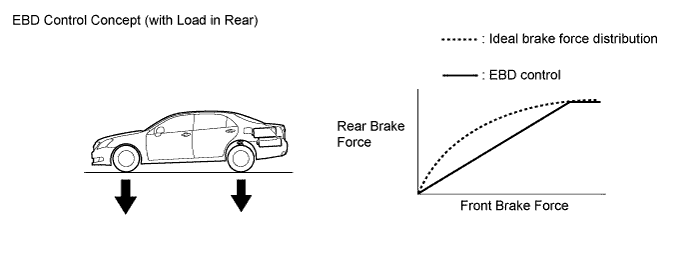
This function controls the brake force that acts on the rear wheels in accordance with the changes in the vehicle conditions such as load factors or deceleration, in order to ensure excellent braking performance.
-
During braking while cornering, this function controls the brake force that acts on the left and right wheels in accordance with the vehicle conditions. This ensures vehicle stability and excellent braking performance.

Text in Illustration 
Control Moment 
Brake Force
-
-
Brake Assist
-
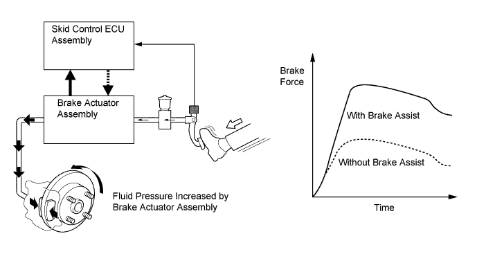
During the brake assist, the skid control ECU assembly calculates the speed and the amount of the brake pedal application based on the signals from the master cylinder pressure sensor and brake pedal stroke sensor assembly, and then determines the intention of the driver to make an emergency brake application. If the skid control ECU assembly determines that the driver intends to make an emergency brake application, this function activates the brake actuator assembly to increase the brake fluid pressure, which increases the brake force.
-
-
Traction Control (TRC)
-
The TRC helps prevent the drive wheels from slipping if the driver depresses the accelerator pedal excessively when starting off or accelerating on a slippery surface. Simultaneously with the hydraulic brake control of the drive wheels, the skid control ECU assembly makes a request to the power management control ECU to effect motive force control. This produces the motive force that suits the driving conditions, in order to ensure the proper start-off acceleration.
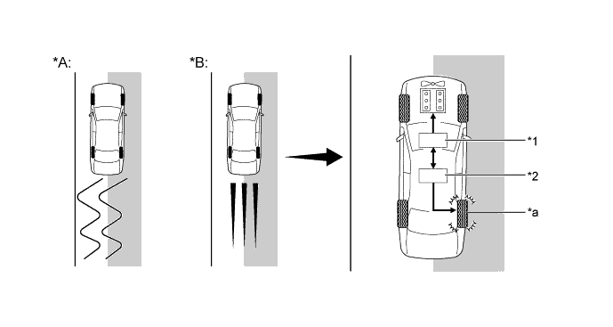
Text in Illustration (Driving on Road with Differing Surface Friction Characteristics) *A Models without TRC *B Models with TRC *1 Power Management Control ECU (Motive Force Control) *2 Skid Control ECU Assembly (Hydraulic Brake Control) *a TRC is Activated - - 
Slippery Surface - -
-
-
Vehicle Stability Control (VSC)
-
The following are 2 examples that can be considered circumstances in which the tires exceed their lateral grip limit. The VSC is designed to help control the vehicle behavior by controlling the motive force and the brakes of each wheel when the vehicle is under one of the conditions indicated below:
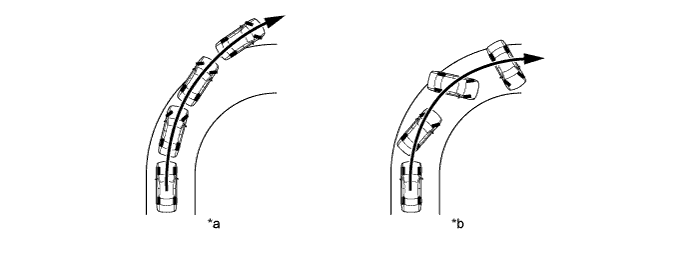
Text in Illustration *a Front Wheel Skid Tendency (Understeer)
- When the front wheels lose grip in relation to the rear wheel
*b Rear Wheel Skid Tendency (Oversteer)
- When the rear wheels lose grip in relation to the front wheels
-
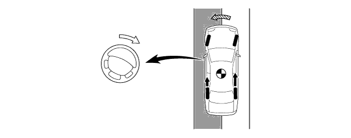
To determine the condition of the vehicle, sensors detect the steering angle, vehicle speed, vehicle yaw rate, and vehicle's lateral acceleration, which are then calculated by the skid control ECU assembly.
-
Whether or not the vehicle is experiencing a front wheel skid is determined by the difference between the target yaw rate and the vehicle's actual yaw rate. When the vehicle's actual yaw rate is smaller than the target yaw rate (which is determined based on the vehicle speed and steering angle) that should be generated when the driver operates the steering wheel, it means the vehicle is making a turn at a greater angle than the target locus of travel. Thus, the skid control ECU assembly determines that there is a large front wheel skid tendency.
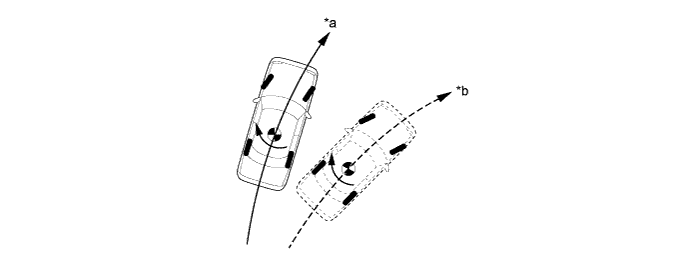
Text in Illustration *a Actual Locus of Travel (Actual Yaw Rate) *b Locus of Travel Based on Target Yaw Rate -
Whether or not the vehicle is experiencing a rear wheel skid is determined by the values of the vehicle's slip angle and the vehicle's slip angular velocity (time-dependent changes in the vehicle's slip angle). When the vehicle's slip angle is large, and the slip angular velocity is also large, the skid control ECU assembly determines that the vehicle has a large rear wheel skid tendency.

Text in Illustration *a Travel Direction of Vehicle's Center of Gravity *b Movement of Vehicle Slip Angle - - -
When the skid control ECU assembly determines that the vehicle is exhibiting a tendency to experience a front wheel skid or a rear wheel skid, it decreases the motive force and applies the brakes of each wheel to control the vehicle's yaw moment. The basic operation of the VSC is described below. However, the control method differs depending on the vehicle's characteristics and driving conditions.
-
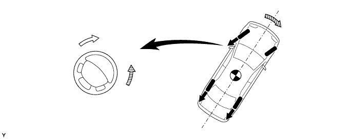
When the skid control ECU assembly determines that there is a large front wheel skid tendency, it takes countermeasures in accordance with the extent of that tendency. The skid control ECU assembly controls the motive force and applies the brakes of both rear wheels and the front wheel on the outside of the turn in order to help restrain the front wheel skid tendency.

Text in Illustration Brake Force - - -
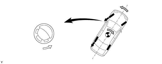
When the skid control ECU assembly determines that there is a large rear wheel skid tendency, it takes countermeasures in accordance with the extent of that tendency. The skid control ECU assembly applies the brakes of the front and rear wheels of the outer circle of the turn, and generates an outward moment of inertia in the vehicle, in order to restrain the rear wheel skid tendency. Along with the reduction in the vehicle speed caused by the braking force, excellent vehicle stability is ensured. In some cases, the skid control ECU applies the brake of the rear wheels, as necessary.

Text in Illustration Control Moment Brake Force
-
-
Steering Cooperative Control
-
If the driver suddenly applies the brakes on a road surface with a considerable difference in friction coefficient between the right and left wheels, the difference in the brake force between the right and left wheels will cause the vehicle posture to become unstable and create a yaw moment. In this state, the skid control ECU assembly controls the VSC to stabilize the vehicle posture.
-
The skid control ECU assembly effects cooperative control with the power steering ECU assembly to provide steering torque assist, which facilitates the driver's steering maneuvers to stabilize the vehicle posture.
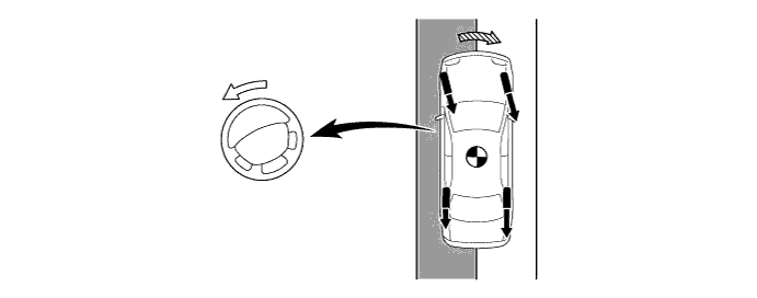
Text in Illustration Steering Torque Assist Direction Brake Force 
Yaw Moment during Brake Control - - Slippery Surface - - -
If the driver suddenly starts off or accelerates on a road surface with a considerable difference in friction coefficient between the right and left wheels, the slippage of a drive wheel will cause the vehicle posture to become unstable and negatively affect its acceleration performance. In this state, the skid control ECU assembly causes the TRC to control the hydraulic brake of the slipping drive wheel, and makes a request to the power management control ECU to effect motive force control.
-
The skid control ECU assembly effects cooperative control with the power steering ECU assembly to provide steering torque assist, which facilitates the driver's steering maneuvers to stabilize the vehicle posture.
Text in Illustration Steering Torque Assist Direction Drive Force Yaw Moment during Acceleration - - Slippery Surface - - -
When the skid control ECU assembly determines a front wheel skid tendency, it controls the VSC to dampen the front wheel skid, and makes a request to the power management control ECU to effect motive force control.
-
The skid control ECU assembly effects cooperative control with the power steering ECU assembly to provide steering torque assist, which controls the driver's steering maneuvers to stabilize the vehicle posture. Steering torque assist is provided to inform the driver of a front wheel skid, and to prevent the driver's excessive turning of the steering wheel. In the assist for preventing excessive turning, the skid control ECU assembly increases the resistance to counter the driver's steering effort, if the driver turns the steering wheel excessively.
Text in Illustration Steering Torque Assist Direction (to Inform of Front Wheel Skid) 
Steering Torque Assist Direction (to Prevent Excessive Turning) Brake Force Moment of Force to Restrict Front Wheel Skid -
When the skid control ECU assembly determines a rear wheel skid tendency, it controls the VSC to dampen the rear wheel skid and makes a request to the power management control ECU to effect motive force control.
-
The skid control ECU assembly effects cooperative control with the power steering ECU assembly to provide steering torque assist, which facilitates the driver's steering maneuvers in the appropriate direction to correct the rear wheel skid.
Text in Illustration Steering Torque Assist Direction Rear Wheel Skid Moment Brake Force Moment of Force to Restrict Rear Wheel Skid
-
-
Brake Hold Function
-
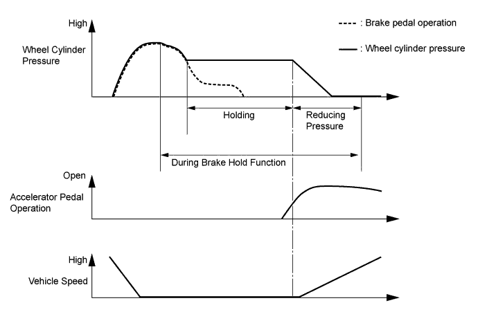
When the driver depresses the brake pedal and brings the vehicle to a stop on a level road surface or gentle slope, the brake hold function maintains the wheel cylinder pressure of the 4 wheels, in order to keep the vehicle stationary. As a result, the vehicle will remain stationary even if the driver reduces the pressure on the brake pedal.
-
While the brake hold function is operating, the skid control ECU assembly illuminates the stoplights.
-
When the driver starts the vehicle off, the system automatically releases the wheel cylinder pressure as the driver depresses the accelerator pedal.
-
-
-
FUNCTION
-
VSC OFF Switch
-
The operation of the VSC and TRC functions can be stopped by the VSC OFF switch. While the vehicle is running off the shoulder of the road or running on a dirt road, the motive force control is stopped to maintain drive torque.
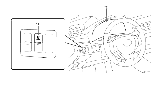
Text in Illustration *1 VSC OFF Switch *2 Combination Meter -
The VSC OFF switch can select 3 modes (Normal mode, TRC OFF mode, and VSC OFF mode).
-
Briefly pressing the VSC OFF switch in Normal mode selects TRC OFF mode.
-
Pressing and holding the VSC OFF switch for 3 seconds or more with the vehicle stopped selects VSC OFF mode, disabling the TRC and VSC functions.
-
Briefly pressing the VSC OFF switch in TRC OFF mode or VSC OFF mode or turning the power switch (push start switch) off returns to the Normal mode.
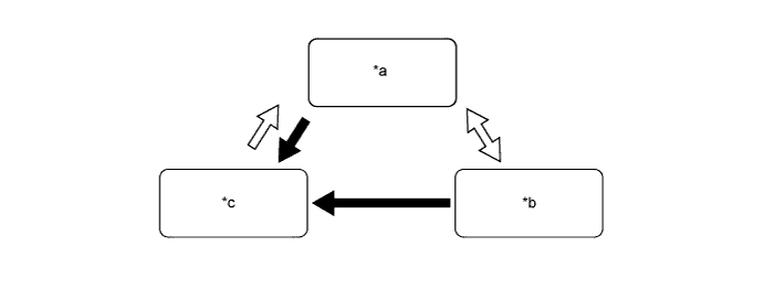
Text in Illustration *a Normal Mode *b TRC OFF Mode *c VSC OFF Mode - - VSC OFF Switch Operation (Press and Hold for 3 Seconds or More) VSC OFF Switch Operation (Brief) -
The operations of the brake control functions in each mode are as follows:
Mode Brake Control Function Combination Meter TRC VSC VSC OFF Indicator Light Multi-information Display Normal Mode Controllable Controllable - - TRC OFF Mode Not Controllable Controllable - Displays VSC OFF Mode Not Controllable Not Controllable* Illuminates - Tech Tips
*: The control is effected during braking or while the yaw rate is large.
-
-
-
CONSTRUCTION
-
Steering Sensor
-
The steering sensor detects the steering direction and angle.
-
2 pairs of magnetoresistive elements are provided in the actuator to detect rotation of the magnet built into the detection gear. The actuator detects magnetic resistance changes during detection of gear rotation as the rotation of the steering wheel.
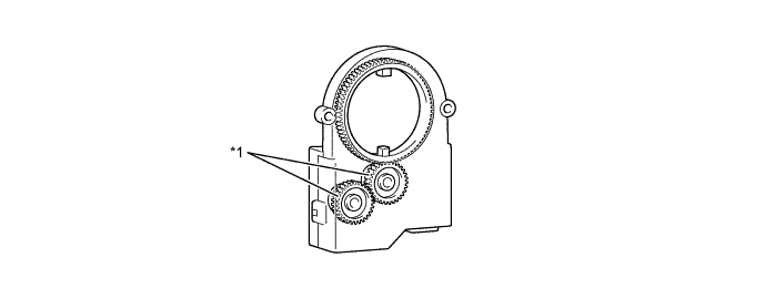
Text in Illustration *1 Detection Gear - -
-
-
Yawrate Sensor
-
The yawrate sensor and the deceleration sensor are integrated together for compactness and located in the lower portion of the center console.
-
The yawrate sensor detects capacitance changes caused by the vehicle's vertical axis rotation as a rotation angle speed.
-
The deceleration sensor detects capacitance changes between the movable electrode and fixed electrode as the vehicle's deceleration. 2 deceleration sensors, installed at 45-degree angles in the vehicle's front and rear directions, are used to enable the detection of the whole vehicle's deceleration in the horizontal direction.

-
-
Speed Sensor
-
An active type speed sensor is used. This sensor contains a sensor IC, which consists of 2 Magnetic Resistance Elements (MREs).
-
The magnet type rotor, which consists of N and S poles that are arranged in a circle, is integrated with the hub bearing inner race.
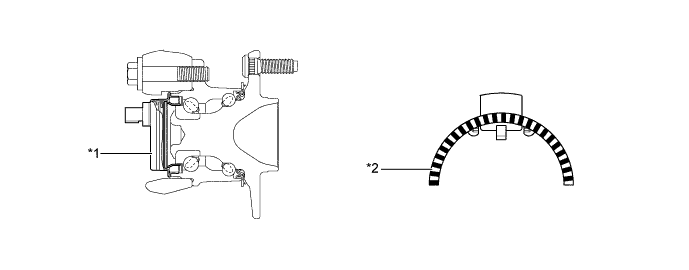
Text in Illustration (Front Axle) *1 Front Speed Sensor *2 Sensor Rotor 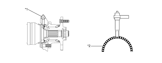
Text in Illustration (Rear Axle) *1 Rear Speed Sensor *2 Sensor Rotor
-
-
Brake Pedal Stroke Sensor Assembly
-
This non-contact type brake pedal stroke sensor uses a Hall IC, which is mounted on the brake pedal support assembly.
-
This sensor detects the extent of the brake pedal stroke and transmits it to the skid control ECU assembly.
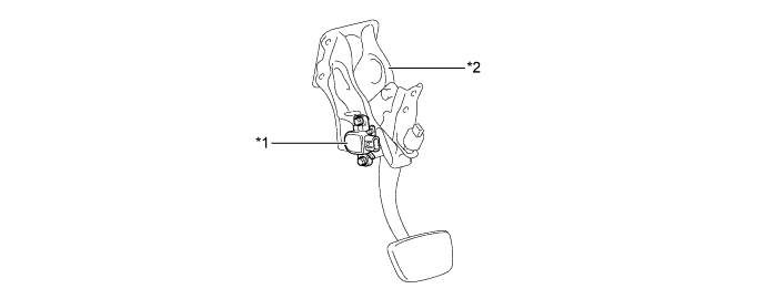
Text in Illustration *1 Brake Pedal Stroke Sensor Assembly *2 Brake Pedal Support Assembly
-
-
Brake Control Power Supply Assembly
-
The brake control power supply is used as an auxiliary power source, in order to supply power to the brake system in a stable manner.
-
The brake control power supply assembly contains 12 capacitor cells, which store an electrical charge provided by the (12 V) vehicle power supply. When the voltage of the (12 V) vehicle power supply drops, the electrical charge stored in the capacitor cells is used as an auxiliary power supply for the brake system.
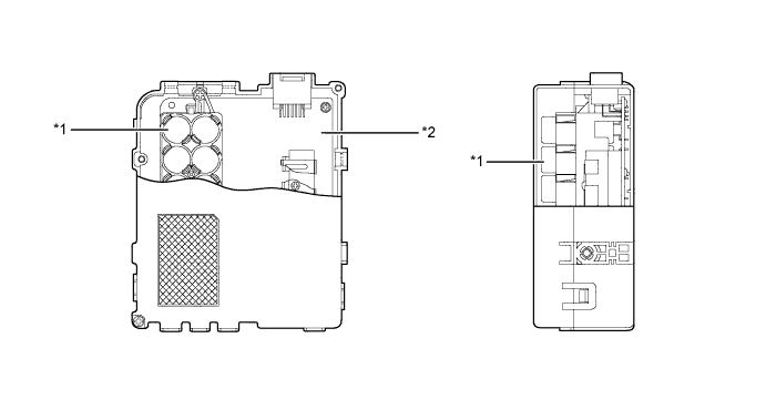
Text in Illustration *1 Capacitor Cell *2 Control Board Tech Tips
Immediately after the power switch (push start switch) is turned off, this brake power supply assembly is in the discharging state, and some voltage remains in the capacitors. Therefore, make sure to check for residual voltage and discharge it if necessary, before removing the brake control power supply assembly from the vehicle or opening and inspecting the inside of the brake control power supply assembly case. For details, refer to the Repair Manual.
-
-
Brake Stroke Simulator Cylinder Sub-assembly
-
The brake stroke simulator cylinder sub-assembly consists of 2 types of coil springs with different spring constants.
-
The brake stroke simulator cylinder sub-assembly produces a natural feeling when operating the brake pedal in response to the driver's depression force by optimally operating the piston in the cylinder.
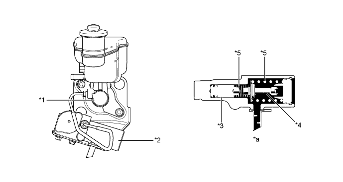
Text in Illustration *1 Brake Master Cylinder Sub-assembly *2 Brake Stroke Simulator Cylinder Sub-assembly *3 Piston *4 Stopper *5 Spring - - *a Brake Stroke Simulator Cylinder Sub-assembly Cross Section - -
-
-
Brake Actuator Assembly
-
The brake actuator assembly consists of hydraulic control and hydraulic power source portions.
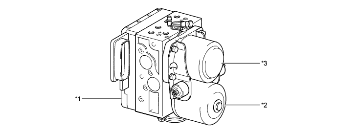
Text in Illustration *1 Hydraulic Control Portion *2 Hydraulic Power Source Portion
- Pump and Pump Motor
*3 Hydraulic Power Source Portion
- Accumulator
- - Function of Brake Actuator Assembly Components Component Function Hydraulic Control Portion Master Cylinder Pressure Sensor The master cylinder pressure sensor converts the fluid pressure generated by the master cylinder into electrical signals and transmits them to the skid control ECU assembly. Accordingly, the skid control ECU assembly determines the braking force required by the driver. Relief Valve This valve returns the brake fluid to the brake master cylinder reservoir assembly to prevent excessive pressure if the pump motor operates continuously due to a malfunction of the accumulator pressure sensor. Accumulator Pressure Sensor This sensor constantly monitors the brake fluid pressure in the accumulator and transmits a signal to the skid control ECU assembly. Accordingly, the skid control ECU assembly controls the pump motor. Master Cylinder Cut Solenoid Valve (Switching Solenoid Valve)
-
When the brake pedal is depressed, this valve cuts the hydraulic passage between the brake master cylinder sub-assembly and the wheel cylinder.
-
When the brake pedal is not depressed or a failure occurs in the hydraulic power source portion, the valves open to maintain the hydraulic passage to the front wheel cylinders and ensure braking.
-
When a failure occurs, a greater effort than normal is required to depress the brake pedal.
Pressure Application Solenoid Valve (Linear Solenoid Valve) This valve is controlled by the skid control ECU assembly, regulating the fluid pressure from the accumulator in order to amplify the fluid pressure to the wheel cylinders. Pressure Reduction Solenoid Valve (Linear Solenoid Valve) This valve is controlled by the skid control ECU, regulating the fluid pressure in order to reduce the fluid pressure to the wheel cylinders. Wheel Cylinder Pressure Sensor This sensor detects the fluid pressure that acts on their respective wheel cylinders and transmits the pressure to the skid control ECU assembly to provide feedback. Accordingly, the skid control ECU assembly can monitor the fluid pressure of the wheel cylinders and control the pressure application solenoid valves and the pressure reduction solenoid valves, in order to achieve the optimal wheel cylinder pressures. Hydraulic Power Source Portion Pump and Pump Motor Draw up the brake fluid from the brake master cylinder reservoir assembly and provides high hydraulic pressure to the accumulator. Accumulator Stores the hydraulic pressure that was generated by the pump. The accumulator is filled with high pressure nitrogen gas. -
-
A plunger type pump is used. This pump is operated by rotation of the camshaft driven by the pump motor, and then supplies high hydraulic pressure to the accumulator.
-
The high pressure nitrogen gas is charged and sealed in the accumulator. A metallic bellows-formed tube is used, in order to enhance the gastight performance of the accumulator.
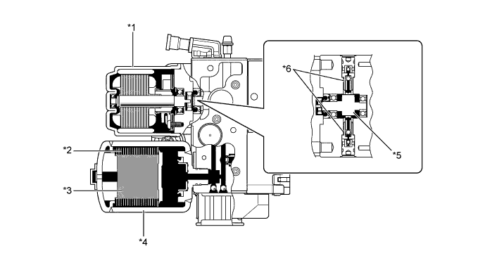
Text in Illustration *1 Pump Motor *2 Bellows-formed *3 High Pressure Nitrogen Gas *4 Accumulator *5 Camshaft *6 Pump -
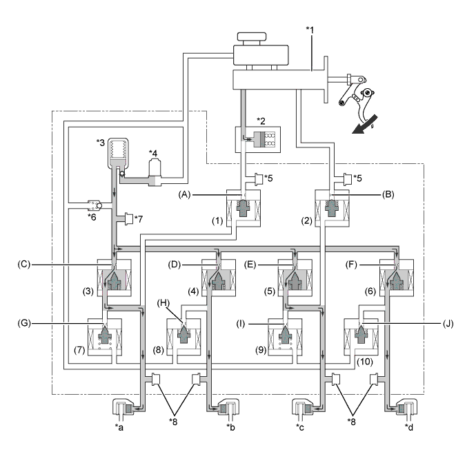
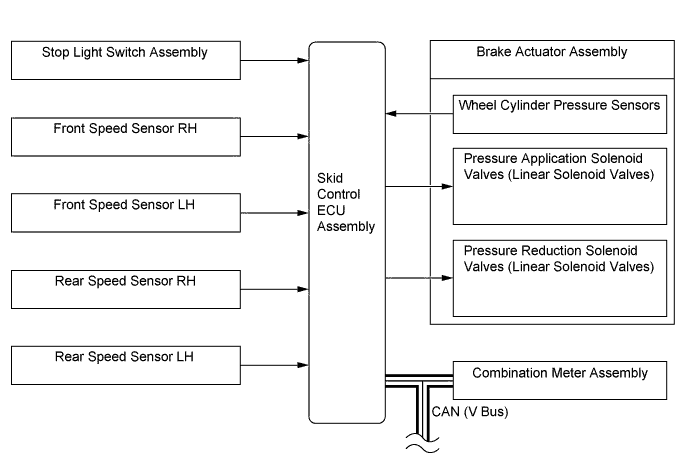
2 master cylinder pressure sensors, 4 wheel cylinder pressure sensors, an accumulator pressure sensor, 2 master cylinder cut solenoid valves, 4 pressure application solenoid valves and 4 pressure reduction solenoid valves are installed in the hydraulic control portion.
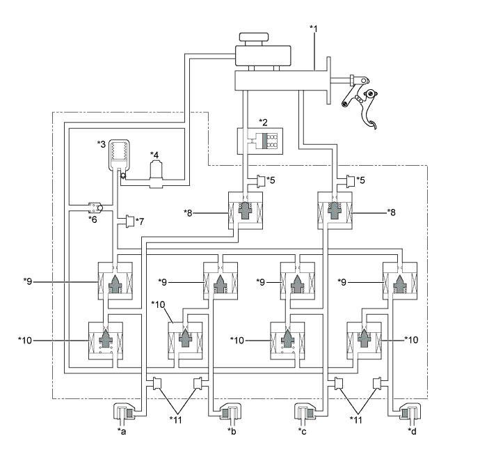
Text in Illustration *1 Brake Master Cylinder Sub-assembly *2 Brake Stroke Simulator Cylinder Sub-assembly *3 Accumulator *4 Pump Motor *5 Master Cylinder Pressure Sensor *6 Relief Valve *7 Accumulator Pressure Sensor *8 Master Cylinder Cut Solenoid Valve (Switching Solenoid Valve) *9 Pressure Application Solenoid Valve (Linear Solenoid Valve) *10 Pressure Reduction Solenoid Valve (Linear Solenoid Valve) *11 Wheel Cylinder Pressure Sensor - - *a Front Brake LH *b Rear Brake RH *c Front Brake RH *d Rear Brake LH -
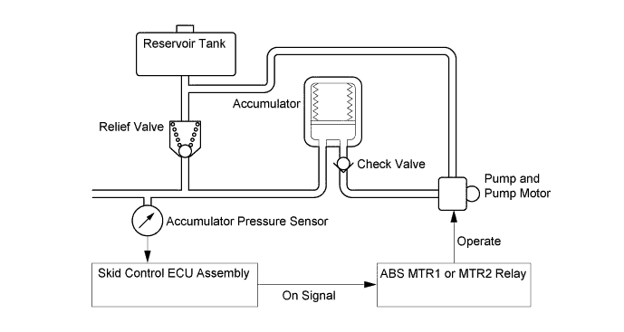
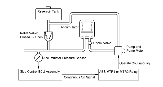
The brake fluid that is discharged by the pump passes through the check valve and is stored in the accumulator. The hydraulic pressure that is stored in the accumulator is used for providing the hydraulic pressure that is needed for normal braking and for operating the brake control.
-
The pump motor is activated upon receipt of signals from the skid control ECU assembly to turn on the ABS MTR1 and ABS MTR2 relays.
-
The accumulator pressure sensor constantly monitors the pressure in the accumulator and transmits it to the skid control ECU assembly. If the accumulator pressure drops below the set pressure, the skid control ECU assembly sends an activation signal to the motor relay in order to actuate the pump motor until the pressure in the accumulator reaches the set pressure.
-
If the pump and the pump motor continue to operate unintendedly, such as due to the failure of the accumulator pressure sensor, a high level of pressure would be created in the accumulator. At this time, the relief valve will open to return the brake fluid to the reservoir tank, to limit the accumulator pressure.
-
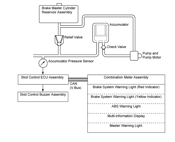
If the accumulator pressure drops abnormally to a level below the pressure set at the ECU, the skid control ECU assembly illuminates the brake system warning light (red indicator), brake system warning light (yellow indicator), ABS warning light and master warning light. Then, a warning message appears on the multi-information display, and the skid control buzzer sounds to alert the driver of the malfunction.
-
-
-
OPERATION
-
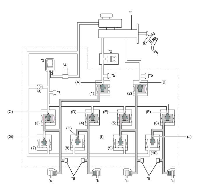
Normal Brake Operation (with Regenerative Brake Cooperative Control)
-
During normal braking, the master cylinder cut solenoid valves are closed and the fluid pressure circuits to the wheel cylinders remain independent. Accordingly, the fluid pressure generated by the brake master cylinder sub-assembly will not directly cause the wheel cylinders to actuate.
-
The skid control ECU assembly calculates the braking force required by the driver in accordance with the signals received from the master cylinder pressure sensors and the brake pedal stroke sensor assembly.
-
Then, the skid control ECU assembly calculates the ECU request regenerative brake force value out of the required brake force and transmits this calculated value to the power management control ECU. Upon receiving the value, the power management control ECU generates a regenerative brake force.
-
At the same time, the power management control ECU transmits the actual regenerative brake force value (regenerative braking execution value) to the skid control ECU assembly. The skid control ECU assembly controls the solenoid valves in order to cause the hydraulic brake system to generate a brake force which is obtained by subtracting the regenerative braking execution value from the brake force value required by the driver.
-
The skid control ECU assembly calculates the target wheel cylinder pressure (equivalent to the brake force required by the driver) in accordance with the signals received from the master cylinder pressure sensor and the brake pedal stroke sensor.
-
The skid control ECU assembly compares the wheel cylinder pressure sensor signal and the target wheel cylinder pressure. If the wheel cylinder pressure is lower than the target, the skid control ECU assembly boosts the pressure using the brake actuator assembly.
-
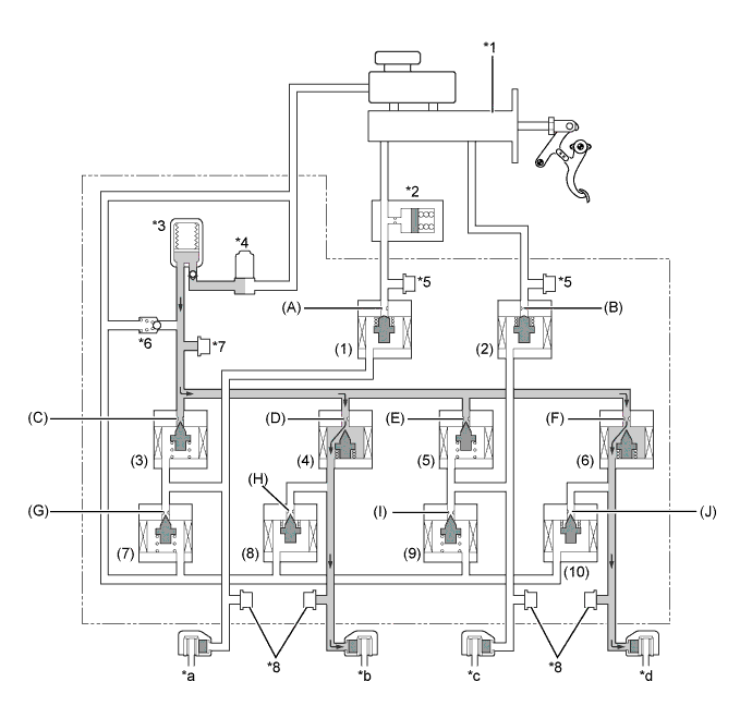
Accordingly, the fluid pressure in the accumulator is fed into the wheel cylinder. Moreover, this operation is the same as when the hydraulic brake force must be increased in order to perform cooperative control in accordance with changes in the regenerative braking force.
Text in Illustration *1 Brake Master Cylinder Sub-assembly *2 Brake Stroke Simulator Cylinder Sub-assembly *3 Accumulator *4 Pump Motor *5 Master Cylinder Pressure Sensor *6 Relief Valve *7 Accumulator Pressure Sensor *8 Wheel Cylinder Pressure Sensor *a Front Brake LH *b Rear Brake RH *c Front Brake RH *d Rear Brake LH -
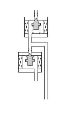
Each valve operates as shown below:
Item Normal Braking Increase Mode (1) Master Cylinder Cut Solenoid Valve (Switching Solenoid Valve) Port (A) On (Closed) (2) Master Cylinder Cut Solenoid Valve (Switching Solenoid Valve) Port (B) On (Closed) (3) Pressure Application Solenoid Valve (Linear Solenoid Valve) Port (C) On* (4) Pressure Application Solenoid Valve (Linear Solenoid Valve) Port (D) On* (5) Pressure Application Solenoid Valve (Linear Solenoid Valve) Port (E) On* (6) Pressure Application Solenoid Valve (Linear Solenoid Valve) Port (F) On* (7) Pressure Reduction Solenoid Valve (Linear Solenoid Valve) Port (G) Off (Closed) (8) Pressure Reduction Solenoid Valve (Linear Solenoid Valve) Port (H) Off (Closed) (9) Pressure Reduction Solenoid Valve (Linear Solenoid Valve) Port (I) Off (Closed) (10) Pressure Reduction Solenoid Valve (Linear Solenoid Valve) Port (J) Off (Closed) Tech Tips
*: The solenoid valve constantly regulates the amount of opening of the port in order to control the fluid pressure.
-
The skid control ECU assembly calculates the target wheel cylinder pressure (equivalent to the brake force required by the driver) in accordance with the signals received from the master cylinder pressure sensor and the brake pedal stroke sensor.
-
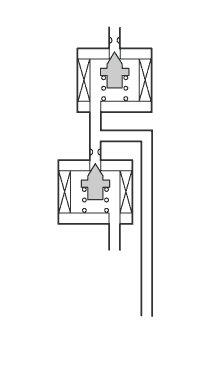
The skid control ECU assembly compares the wheel cylinder pressure signal with the target wheel cylinder pressure. If they are equal, the skid control ECU assembly holds the pressure using the brake actuator assembly.
-
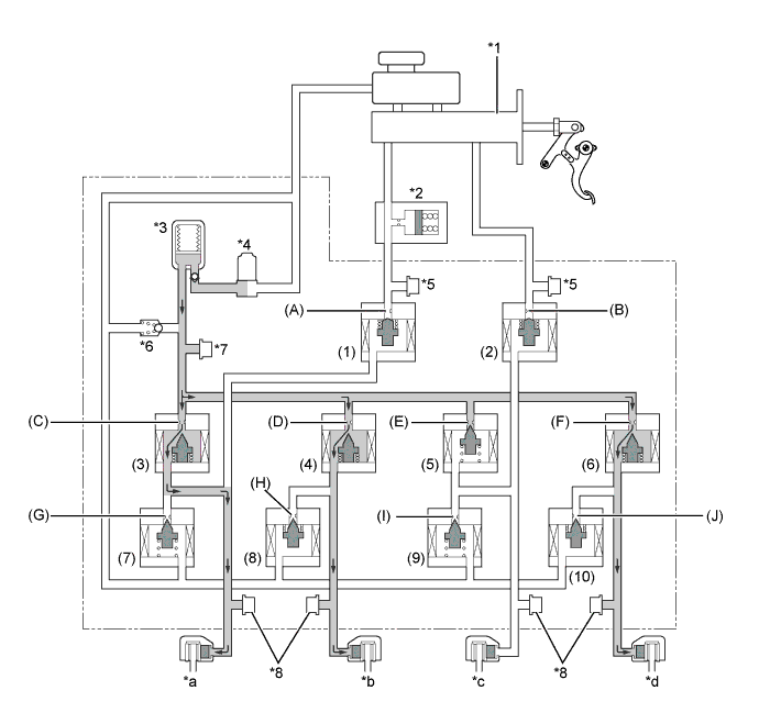
Accordingly, the wheel cylinder will be held at a constant pressure.
Text in Illustration *1 Brake Master Cylinder Sub-assembly *2 Brake Stroke Simulator Cylinder Sub-assembly *3 Accumulator *4 Pump Motor *5 Master Cylinder Pressure Sensor *6 Relief Valve *7 Accumulator Pressure Sensor *8 Wheel Cylinder Pressure Sensor *a Front Brake LH *b Rear Brake RH *c Front Brake RH *d Rear Brake LH -
Each valve operates as shown below:
Item Normal Braking Increase Mode (1) Master Cylinder Cut Solenoid Valve (Switching Solenoid Valve) Port (A) On (Closed) (2) Master Cylinder Cut Solenoid Valve (Switching Solenoid Valve) Port (B) On (Closed) (3) Pressure Application Solenoid Valve (Linear Solenoid Valve) Port (C) Off (Closed) (4) Pressure Application Solenoid Valve (Linear Solenoid Valve) Port (D) Off (Closed) (5) Pressure Application Solenoid Valve (Linear Solenoid Valve) Port (E) Off (Closed) (6) Pressure Application Solenoid Valve (Linear Solenoid Valve) Port (F) Off (Closed) (7) Pressure Reduction Solenoid Valve (Linear Solenoid Valve) Port (G) Off (Closed) (8) Pressure Reduction Solenoid Valve (Linear Solenoid Valve) Port (H) On (Closed) (9) Pressure Reduction Solenoid Valve (Linear Solenoid Valve) Port (I) Off (Closed) (10) Pressure Reduction Solenoid Valve (Linear Solenoid Valve) Port (J) On (Closed) -
The skid control ECU assembly calculates the target wheel cylinder pressure (equivalent to the brake force required by the driver) in accordance with the signals received from the master cylinder pressure sensor and the brake pedal stroke sensor.
-
The skid control ECU assembly compares the wheel cylinder pressure signal with the target wheel cylinder pressure. If wheel cylinder pressure is higher than the target pressure, the skid control ECU assembly reduces the pressure using the brake actuator.
-
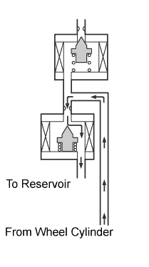
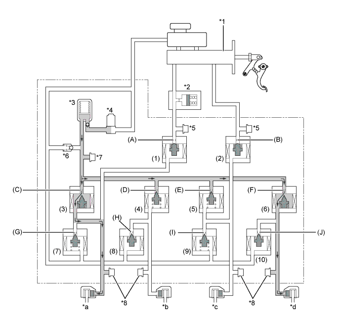
Accordingly, the pressure in the wheel cylinder decreases.
-
Moreover, this operation is the same as when the hydraulic brake force must be decreased in order to perform cooperative control in accordance with changes in the regenerative braking force.
Text in Illustration *1 Brake Master Cylinder Sub-assembly *2 Brake Stroke Simulator Cylinder Sub-assembly *3 Accumulator *4 Pump Motor *5 Master Cylinder Pressure Sensor *6 Relief Valve *7 Accumulator Pressure Sensor *8 Wheel Cylinder Pressure Sensor *a Front Brake LH *b Rear Brake RH *c Front Brake RH *d Rear Brake LH -
Each valve operates as shown below:
Item Normal Braking Increase Mode (1) Master Cylinder Cut Solenoid Valve (Switching Solenoid Valve) Port (A) On (Closed) (2) Master Cylinder Cut Solenoid Valve (Switching Solenoid Valve) Port (B) On (Closed) (3) Pressure Application Solenoid Valve (Linear Solenoid Valve) Port (C) Off (Closed) (4) Pressure Application Solenoid Valve (Linear Solenoid Valve) Port (D) Off (Closed) (5) Pressure Application Solenoid Valve (Linear Solenoid Valve) Port (E) Off (Closed) (6) Pressure Application Solenoid Valve (Linear Solenoid Valve) Port (F) Off (Closed) (7) Pressure Reduction Solenoid Valve (Linear Solenoid Valve) Port (G) On* (8) Pressure Reduction Solenoid Valve (Linear Solenoid Valve) Port (H) On* (9) Pressure Reduction Solenoid Valve (Linear Solenoid Valve) Port (I) On* (10) Pressure Reduction Solenoid Valve (Linear Solenoid Valve) Port (J) On* Tech Tips
*: The solenoid valve constantly regulates the amount of opening of the port in order to control the fluid pressure.
-
-
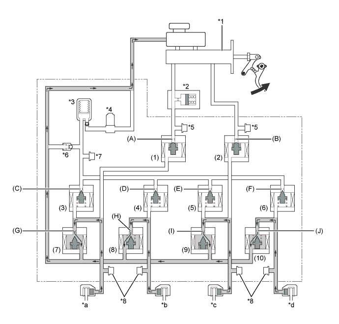
When Electronically Controlled Brake System Stops or during Power Supply Malfunction
-
If the electronically controlled brake system stops or no accumulator pressure is supplied due to a malfunction, the skid control ECU assembly operates the fail-safe function.
-
This function opens the master cylinder cut solenoid valve in the brake actuator assembly, in order to secure a fluid passage between the brake master cylinder sub-assembly and the wheel cylinder. Thus, the brakes can be applied by operating only the front wheel cylinders using the fluid pressure generated by the brake master cylinder sub-assembly.
-
In addition, to inform the driver, the skid control ECU assembly sends a warning signal to the combination meter assembly in addition to sounding the skid control buzzer assembly.
Text in Illustration *1 Brake Master Cylinder Sub-assembly *2 Brake Stroke Simulator Cylinder Sub-assembly *3 Accumulator *4 Pump Motor *5 Master Cylinder Pressure Sensor *6 Relief Valve *7 Accumulator Pressure Sensor *8 Wheel Cylinder Pressure Sensor *a Front Brake LH *b Rear Brake RH *c Front Brake RH *d Rear Brake LH -
Each valve operates as shown below:
Item Normal Braking Increase Mode (1) Master Cylinder Cut Solenoid Valve (Switching Solenoid Valve) Port (A) Off (Open) (2) Master Cylinder Cut Solenoid Valve (Switching Solenoid Valve) Port (B) Off (Open) (3) Pressure Application Solenoid Valve (Linear Solenoid Valve) Port (C) Off (Closed) (4) Pressure Application Solenoid Valve (Linear Solenoid Valve) Port (D) Off (Closed) (5) Pressure Application Solenoid Valve (Linear Solenoid Valve) Port (E) Off (Closed) (6) Pressure Application Solenoid Valve (Linear Solenoid Valve) Port (F) Off (Closed) (7) Pressure Reduction Solenoid Valve (Linear Solenoid Valve) Port (G) Off (Closed) (8) Pressure Reduction Solenoid Valve (Linear Solenoid Valve) Port (H) Off (Open) (9) Pressure Reduction Solenoid Valve (Linear Solenoid Valve) Port (I) Off (Closed) (10) Pressure Reduction Solenoid Valve (Linear Solenoid Valve) Port (J) Off (Open)
-
-
ABS and EBD Operation
-
Based on the signals received from the 4 speed sensors, the skid control ECU assembly calculates each wheel speed and checks for wheel slippage. In accordance with the wheel slippage, the skid control ECU assembly controls each pressure application solenoid valve and pressure reduction solenoid valve in order to adjust the fluid pressure of the each wheel cylinder in the following 3 modes: pressure reduction, pressure holding and pressure increase modes.
Not Activated Normal Braking - - Activated Increase Mode Holding Mode Reduction Mode Front Brake Hydraulic Circuit 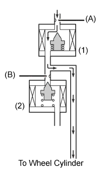
(1) Pressure Application Solenoid Valve Port (A) On* Off (Closed) ← (2) Pressure Reduction Solenoid Valve Port (B) Off (Closed) ← On* Rear Brake Hydraulic Circuit 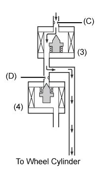
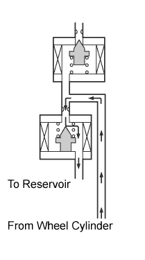
(3) Pressure Application Solenoid Valve Port (C) On* Off (Closed) ← (4) Pressure Reduction Solenoid Valve Port (D) On (Closed) ← On* Wheel Cylinder Pressure Increases Holds Reduces Tech Tips
*: The solenoid valve constantly regulates the amount of opening of the port in order to control the fluid pressure.
-
-
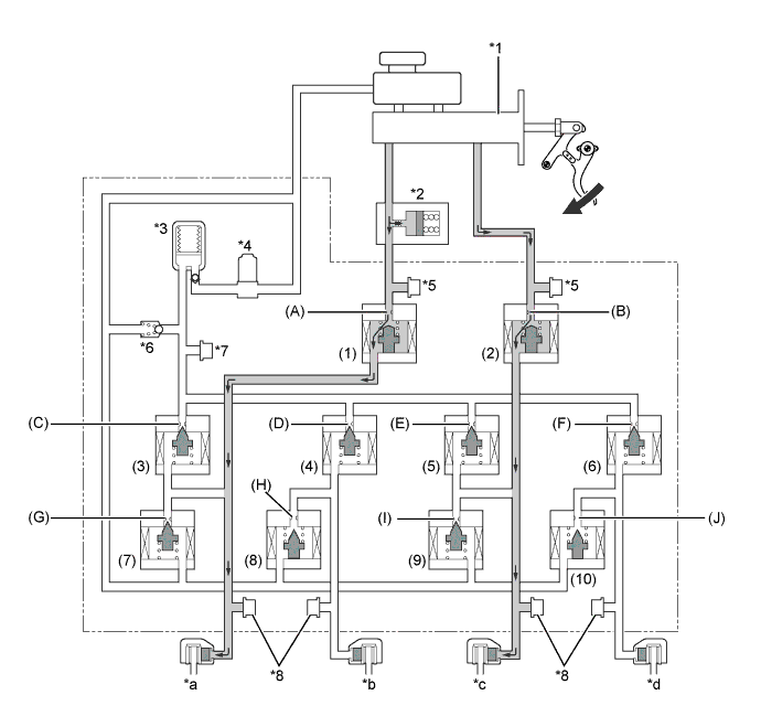
Brake Assist Operation
-
In the event of emergency braking, the skid control ECU assembly detects the driver's intention based on the speed of the pressure increase in the brake master cylinder subassembly determined by the pressure sensor signals. If the ECU judges the need for the additional brake assist, additional fluid pressure is generated by the pump motor in the brake actuator assembly and directed to the wheel cylinders.
Text in Illustration *1 Brake Master Cylinder Sub-assembly *2 Brake Stroke Simulator Cylinder Sub-assembly *3 Accumulator *4 Pump Motor *5 Master Cylinder Pressure Sensor *6 Relief Valve *7 Accumulator Pressure Sensor *8 Wheel Cylinder Pressure Sensor *a Front Brake LH *b Rear Brake RH *c Front Brake RH *d Rear Brake LH -
Each valve operates as shown below:
Item Normal Braking Increase Mode Brake Assist Activated (1) Master Cylinder Cut Solenoid Valve (Switching Solenoid Valve) Port (A) On (Closed) ← (2) Master Cylinder Cut Solenoid Valve (Switching Solenoid Valve) Port (B) On (Closed) ← (3) Pressure Application Solenoid Valve (Linear Solenoid Valve) Port (C) On* ← (4) Pressure Application Solenoid Valve (Linear Solenoid Valve) Port (D) On* ← (5) Pressure Application Solenoid Valve (Linear Solenoid Valve) Port (E) On* ← (6) Pressure Application Solenoid Valve (Linear Solenoid Valve) Port (F) On* ← (7) Pressure Reduction Solenoid Valve (Linear Solenoid Valve) Port (G) Off (Closed) ← (8) Pressure Reduction Solenoid Valve (Linear Solenoid Valve) Port (H) On (Closed) ← (9) Pressure Reduction Solenoid Valve (Linear Solenoid Valve) Port (I) Off (Closed) ← (10) Pressure Reduction Solenoid Valve (Linear Solenoid Valve) Port (J) On (Closed) ←
-
-
TRC Operation
-
The fluid pressure generated by the pump motor is regulated by the pressure application solenoid valve and pressure reduction solenoid valve to the required pressure. Thus, the wheel cylinders of the drive wheels are controlled in the following 3 modes: pressure reduction, pressure holding and pressure increase modes, to restrain the slippage of the drive wheels.
-
The pressure application solenoid valve and the pressure reduction solenoid valve are turned on and off in accordance with the ABS operation pattern.
-
The diagram shows the hydraulic circuit in the pressure increase mode when the TRC function is activated.
Text in Illustration *1 Brake Master Cylinder Sub-assembly *2 Brake Stroke Simulator Cylinder Sub-assembly *3 Accumulator *4 Pump Motor *5 Master Cylinder Pressure Sensor *6 Relief Valve *7 Accumulator Pressure Sensor *8 Wheel Cylinder Pressure Sensor *a Front Brake LH *b Rear Brake RH *c Front Brake RH *d Rear Brake LH -
Each valve operates as shown below:
Item TRC Not Activated TRC Activated Increase Mode Holding Mode Reduction Mode (1) Master Cylinder Cut Solenoid Valve (Switching Solenoid Valve) Port (A) On (Closed) ← ← ← (2) Master Cylinder Cut Solenoid Valve (Switching Solenoid Valve) Port (B) On (Closed) ← ← ← (3) Pressure Application Solenoid Valve (Linear Solenoid Valve) Port (C) Off (Closed) ← ← ← (4) Pressure Application Solenoid Valve (Linear Solenoid Valve) Port (D) Off (Closed) On* Off (Closed) ← (5) Pressure Application Solenoid Valve (Linear Solenoid Valve) Port (E) Off (Closed) ← ← ← (6) Pressure Application Solenoid Valve (Linear Solenoid Valve) Port (F) Off (Closed) On* Off (Closed) ← (7) Pressure Reduction Solenoid Valve (Linear Solenoid Valve) Port (G) Off (Closed) ← ← ← (8) Pressure Reduction Solenoid Valve (Linear Solenoid Valve) Port (H) Off (Open) On (Closed) ← On* (9) Pressure Reduction Solenoid Valve (Linear Solenoid Valve) Port (I) Off (Closed) ← ← ← (10) Pressure Reduction Solenoid Valve (Linear Solenoid Valve) Port (J) Off (Open) On (Closed) ← On* Tech Tips
*: The solenoid valve constantly regulates the amount of opening of the port in order to control the fluid pressure.
-
-
VSC Operation
-
The VSC controls the solenoid valves in order to send the fluid pressure stored in the accumulator to the brake wheel cylinders at the respective wheels, through routes that are different from those used during normal braking. Thus, the function operates in the following 3 modes: pressure reduction, pressure holding and pressure increase modes. As a result, the tendency of the front wheels or the rear wheels to skid is restrained.
-
In the front wheel skid restraining control, the brakes of the front wheel on the outer circle of the turn and the rear wheels are applied. Also, depending on whether the brake is on or off and also depending on the condition of the vehicle, there are circumstances in which the brake might not be applied to the wheels even if the wheel is targeted for braking. The following diagram shows the hydraulic circuit in the pressure increase mode, as it controls the front wheel skid condition while the vehicle is making a right turn.
-
The pressure application solenoid valve and the pressure reduction solenoid valve are turned on and off in accordance with the ABS operation pattern.
Text in Illustration *1 Brake Master Cylinder Sub-assembly *2 Brake Stroke Simulator Cylinder Sub-assembly *3 Accumulator *4 Pump Motor *5 Master Cylinder Pressure Sensor *6 Relief Valve *7 Accumulator Pressure Sensor *8 Wheel Cylinder Pressure Sensor *a Front Brake LH *b Rear Brake RH *c Front Brake RH *d Rear Brake LH -
Each valve operates as shown below:
Item VSC Not Activated VSC Activated Increase Mode Holding Mode Reduction Mode (1) Master Cylinder Cut Solenoid Valve (Switching Solenoid Valve) Port (A) On (Closed) ← ← ← (2) Master Cylinder Cut Solenoid Valve (Switching Solenoid Valve) Port (B) On (Closed) ← ← ← (3) Pressure Application Solenoid Valve (Linear Solenoid Valve) Port (C) Off (Closed) On* Off (Closed) ← (4) Pressure Application Solenoid Valve (Linear Solenoid Valve) Port (D) Off (Closed) On* Off (Closed) ← (5) Pressure Application Solenoid Valve (Linear Solenoid Valve) Port (E) Off (Closed) ← ← ← (6) Pressure Application Solenoid Valve (Linear Solenoid Valve) Port (F) Off (Closed) On* Off (Closed) ← (7) Pressure Reduction Solenoid Valve (Linear Solenoid Valve) Port (G) Off (Closed) ← ← On* (8) Pressure Reduction Solenoid Valve (Linear Solenoid Valve) Port (H) Off (Open) On (Closed) ← On* (9) Pressure Reduction Solenoid Valve (Linear Solenoid Valve) Port (I) Off (Closed) ← ← ← (10) Pressure Reduction Solenoid Valve (Linear Solenoid Valve) Port (J) Off (Open) On (Closed) ← On* Tech Tips
*: The solenoid valve constantly regulates the amount of opening of the port in order to control the fluid pressure.
-
During the rear wheel skid restraining control, the brakes of the front and rear wheels on the outer circle of the turn are applied. Also, depending on whether the brake is on or off and also depending on the condition of the vehicle, there are circumstances in which the brake might not be applied to the wheels even if the wheel is targeted for braking. The following diagram shows the hydraulic circuit in the pressure increase mode, as it controls the rear wheel skid condition while the vehicle is making a right turn.
-
As in rear wheel skid restraint control, the pressure application solenoid valve and the pressure reduction solenoid valve are turned on and off in accordance with the ABS operating pattern.
Text in Illustration *1 Brake Master Cylinder Sub-assembly *2 Brake Stroke Simulator Cylinder Sub-assembly *3 Accumulator *4 Pump Motor *5 Master Cylinder Pressure Sensor *6 Relief Valve *7 Accumulator Pressure Sensor *8 Wheel Cylinder Pressure Sensor *a Front Brake LH *b Rear Brake RH *c Front Brake RH *d Rear Brake LH -
Each valve operates as shown below:
Item VSC Not Activated VSC Activated Increase Mode Holding Mode Reduction Mode (1) Master Cylinder Cut Solenoid Valve (Switching Solenoid Valve) Port (A) On (Closed) ← ← ← (2) Master Cylinder Cut Solenoid Valve (Switching Solenoid Valve) Port (B) On (Closed) ← ← ← (3) Pressure Application Solenoid Valve (Linear Solenoid Valve) Port (C) Off (Closed) On* Off (Closed) ← (4) Pressure Application Solenoid Valve (Linear Solenoid Valve) Port (D) Off (Closed) ← ← ← (5) Pressure Application Solenoid Valve (Linear Solenoid Valve) Port (E) Off (Closed) ← ← ← (6) Pressure Application Solenoid Valve (Linear Solenoid Valve) Port (F) Off (Closed) On* Off (Closed) ← (7) Pressure Reduction Solenoid Valve (Linear Solenoid Valve) Port (G) Off (Closed) ← ← On* (8) Pressure Reduction Solenoid Valve (Linear Solenoid Valve) Port (H) Off (Open) ← ← ← (9) Pressure Reduction Solenoid Valve (Linear Solenoid Valve) Port (I) Off (Closed) ← ← ← (10) Pressure Reduction Solenoid Valve (Linear Solenoid Valve) Port (J) Off (Open) On (Closed) ← On* Tech Tips
*: The solenoid valve constantly regulates the amount of opening of the port in order to control the fluid pressure.
-
-
Brake Hold Function
-
Based on the signals received from the yawrate sensor, the skid control ECU assembly applies a wheel cylinder pressure to the 4 wheels that is appropriate for the gradient condition of the road surface. As a result, the vehicle will remain stationary even if the driver reduces the pressure on the brake pedal. If the vehicle moves while the brake hold function is operating, the skid control ECU assembly increases the wheel cylinder pressure in order to keep the vehicle stopped.
-
The fluid pressure that has been generated by the pump in the brake actuator is directed to the wheel cylinder.
-
-
-
FAIL-SAFE
-
If a failure occurs in the skid control ECU assembly, sensors or brake actuator assembly, the system continues effecting brake control by excluding the failed area and using only the areas that are operating normally.
-
If the regenerative brake becomes unusable due to a failure in communication with the power management control ECU, the skid control ECU assembly uses the hydraulic brake force to control the entire braking force.
-
-
DIAGNOSIS
-
If the skid control ECU assembly detects a malfunction in the brake control system, the warning lights illuminate and a warning message is displayed on the multi-information display. At the same time, a Diagnostic Trouble Code (DTC) is stored in the memory of the skid control ECU assembly.
-
If the skid control ECU assembly detects a malfunction during a sensor signal check (test mode), it stores the DTCs in its memory.
-
For details of DTCs and the check function, refer to the Repair Manual.
-