DYNAMIC REAR STEERING SYSTEM DETAILS
-
FUNCTION OF MAIN COMPONENTS
Component Function Rear Steering Link Assembly Motor Rotates to create the turning angle of the rear wheel upon receiving the signals from the rear steering control ECU. Reduction Mechanism Uses a planetary gear type reduction mechanism to reduce the rotation of the motor. Stroke Sensor Detects the stroke amount of the rear steering link assembly. Rotation Angle Sensor Transmits the rotation angle of the motor to the rear steering control ECU. Combination Meter Assembly Multi-information Display Displays the warning message to inform the driver of a malfunction in the system. Master Warning Light Illuminates when the warning message is displayed in the multi-information display. Multi Buzzer Sounds to warn the driver of a malfunction in the system. Steering Sensor Detects the steering direction and angle of the steering wheel. Rear Steering Control ECU Drives the motor in the rear steering link assembly in accordance with a control angle signal from the front steering control ECU. Front Steering Control ECU
-
Calculates the target vehicle characteristics based on the signals from the steering sensor, vehicle speed and each ECU.
-
Drives the motor of the steering actuator assembly.
-
Sends the control signal to the rear steering control ECU.
Power Steering ECU Assembly Sends the steering assist signal to the front steering control ECU. Skid Control ECU Assembly
-
Outputs the vehicle speed signal.
-
Requests the control of the turning angle of the front wheel and rear wheel during cooperative control.
Absorber Control ECU Outputs the damping force control condition. Driving Support ECU Assembly (Models with Pre-crash Safety System) Requests the control of the turning angle of the front wheel and rear wheel during cooperative control. -
-
CONSTRUCTION
-
Rear Steering Link Assembly
-
The rear steering link assembly is located on the same axis as the motor and reduction mechanism, thus giving a compact construction.
Note
Please make sure to jack the vehicle up when forcibly driving the rear steering link assembly using the Global TechStream (GTS).
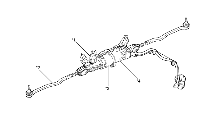
Text in Illustration *1 Stroke Sensor *2 Rear Steering Rack End Assembly *3 Reduction Mechanism Portion *4 Motor
-
-
Motor and Reduction Mechanism
-
The motor is a brushless type motor that has high power output, low inertia and low noise.
-
The motor is located on the same axis as the rear steering rod, and it consists of a rotation angle sensor, a rotor and a stator.
-
A planetary gear is used for the reduction mechanism, and a sun gear is located at the edge of the rotor. The rotation of the rotor is reduced by the planetary gear and is transmitted to the rear steering nut, which is connected to the carrier. The rotation of the rear steering nut causes the rear steering rod to stroke.
-
The shape and location of the rear steering nut have been optimized, thus ensuring output effectiveness and strength and also enhancing holding force in reaction to input from the road surface.
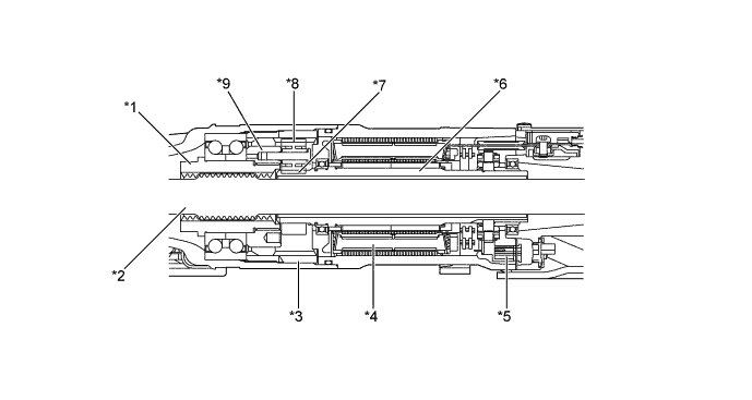
Text in Illustration *1 Rear Steering Nut *2 Rear Steering Rod *3 Ring Gear *4 Stator *5 Rotation Angle Sensor *6 Rotor *7 Sun Gear *8 Planetary Gear *9 Carrier - -
-
-
Stroke Sensor
-
A resolver sensor type stroke sensor is used.
-
A gear mechanism is used to convert the stroke of the rear steering rod into the rotation of the stroke sensor, thus detecting the position of the rear steering rod.

Text in Illustration *1 Gear *2 Rear Steering Rod *3 Resolver Sensor - -
-
-
-
FAIL-SAFE
-
If a malfunction occurs in the DRS system, the rear steering control ECU gradually reduces or blocks current output to the motor to ban control of the turning angle of the rear wheels.
-
-
DIAGNOSIS
-
If the rear steering control ECU detects a malfunction in the DRS system, it lights up the master warning light, indicates the warning message on the multi-information display, sounds the multi buzzer to alert the driver of the malfunction.
-
The rear steering control ECU will also store a Diagnostic Trouble Code (DTC). The DTC can be accessed through the use of a Global TechStream (GTS). For details, refer to the Repair Manual.
-