FUEL SYSTEM DETAILS
-
FUNCTION OF MAIN COMPONENTS
-
The D-4S system has the following components and functions:
Component Function Fuel Pump Assembly (for Low Pressure) Sends fuel (400 kPa) from the fuel tank assembly to the fuel pump assembly (for high pressure) and fuel injector assembly (for port injection). Fuel Pump Assembly (for High Pressure) Increases the pressure of the fuel from the fuel pump assembly (for low pressure) to a pressure of 2.4 to 18 MPa and sends it to the fuel delivery pipe sub-assembly (for direct injection). Spill Control Valve Closes and opens the fuel flow path to the high-pressure fuel system in accordance with signals from the EDU (Injector Driver). Fuel Delivery Pipe Sub-assembly (for Port Injection) Delivers the low-pressure fuel to the fuel injector assembly (for port injection). Fuel Delivery Pipe Sub-assembly (for Direct Injection) Delivers the high-pressure fuel to the fuel injector assembly (for direct injection). Fuel Pressure Pulsation Damper Assembly Reduces the fuel pressure fluctuation (pulsation) and noise. Fuel Pressure Sensor Senses the fuel pressure and outputs a signal to the ECM. Fuel Injector Assembly (for Port Injection) Injects a calculated (by the ECM) quantity of 400 kPa (low pressure) fuel into the intake port. Fuel Injector Assembly (for Direct Injection) Injects a calculated (by the ECM) quantity of 2.4 to 18 MPa (high pressure) fuel directly into the combustion chamber. Solenoid Valve Assembly Applies current to the coils based on a signal from the ECM and returns fuel to the fuel tank assembly. EDU (Injector Driver) Transforms signals sent from the ECM (fuel injection request and high-pressure fuel injection volume control) into high-pressure and high-voltage operation signals in order to operate the fuel injector assemblies (for direct injection) and spill control valve at high-speed. ECM Depending on the vehicle condition, and based on signals from various sensors, the ECM calculates the optimal injection timing and volume, and controls the fuel injector assembly (for direct injection) and fuel pump assembly (for high pressure).
-
-
CONSTRUCTION
-
Fuel Pump Assembly (for Low Pressure)
-
A compact fuel pump assembly is used. Its basic components are a fuel pump, a fuel filter assembly, a fuel pressure regulator assembly, a fuel main valve assembly, a fuel main valve assembly (return) and a fuel sender gauge assembly.
-
The fuel pump assembly (for low pressure) is located in the fuel tank assembly. This fuel pump pressurizes the fuel from the fuel tank assembly and sends the fuel to the high-pressure and low-pressure fuel systems.
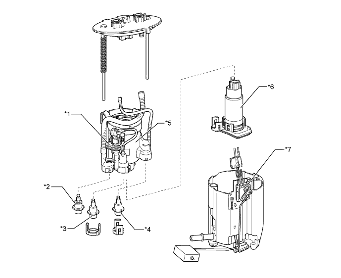
Text in Illustration *1 Jet Pump *2 Fuel Main Valve Assembly *3 Fuel Pressure Regulator Assembly *4 Fuel Main Valve Assembly (Return) *5 Fuel Filter Assembly *6 Fuel Pump *7 Fuel Sender Gauge Assembly - - -
By integrating the fuel filter assembly, fuel pressure regulator assembly and fuel pump, it is possible to discontinue the return of fuel from the engine area, thus preventing temperature rise inside the fuel tank assembly. This reduces the generation of evaporative emissions in the fuel tank assembly.
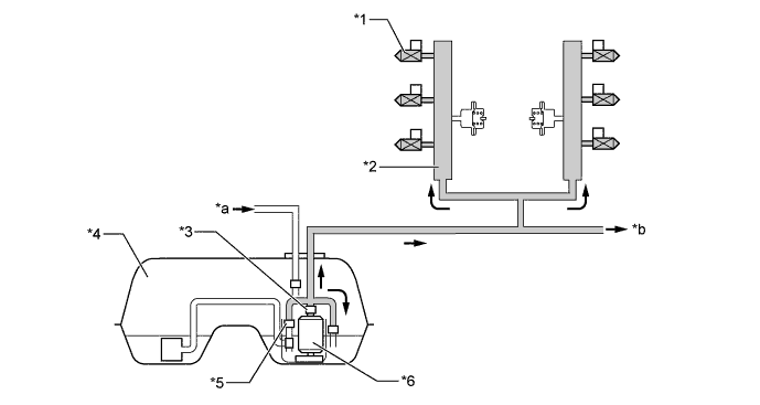
Text in Illustration *1 Fuel Injector Assembly (for Port Injection) *2 Fuel Delivery Pipe Sub-assembly (for Port Injection) *3 Fuel Filter Assembly *4 Fuel Tank Assembly *5 Fuel Main Valve Assembly *6 Fuel Pump Assembly *a Return Fuel (for High Pressure) *b To High-pressure Fuel System 
Low-pressure Fuel - -
-
-
Fuel Pump Assembly (for High Pressure)
-
The fuel pump assembly (for high pressure) consists of a plunger, a spill control valve, a check valve and a relief valve.
-
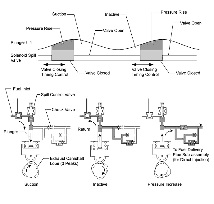
The plunger is moved up and down by a lobe that is located at the rear end of the exhaust camshaft on the right bank of the engine. This lobe causes 3 strokes of the pump piston to occur for each camshaft revolution (3 protrusions exist 120 degrees from each other on the same camshaft "lobe").
-
The plunger is driven by the roller lifter (fuel pump lifter assembly) to accommodate a high level of output and fuel pressure.
-
A fuel pressure pulsation damper is provided at the place where low pressure fuel enters from the fuel tank assembly, thus reducing fuel pulsation.
-
An orifice to reduce fuel pressure when the engine is stopped is used.
-
A spill control valve is used to control the pump discharge pressure. The spill control valve is located in the inlet passage of the fuel pump assembly (for high pressure). The valve is electrically opened and closed by the EDU, based on instructions from the ECM.
-
A check valve is present in the outlet of the fuel pump assembly (for high pressure). As the pressure in the outlet of the pump rises, and becomes high enough to push the check valve off its seat, fuel will begin to flow to the fuel delivery pipe sub-assembly (for direct injection), (minimum pressure to open the check valve is 60 kPa).
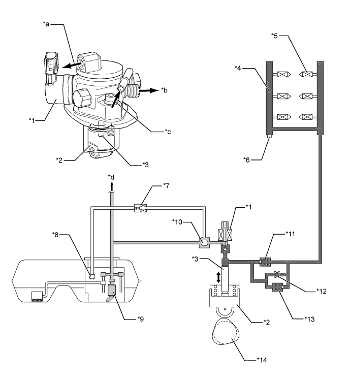
Text in Illustration *1 Spill Control Valve *2 Fuel Pump Lifter Assembly *3 Plunger *4 Fuel Delivery Pipe Sub-assembly (for Direct Injection) *5 Fuel Injector Assembly (for Direct Injection) *6 Fuel Pressure Sensor *7 Solenoid Valve Assembly *8 Fuel Main Valve Assembly (Return) *9 Fuel Pump Assembly (for Low Pressure) *10 Fuel Pressure Pulsation Damper *11 Check Valve *12 Orifice *13 Relief Valve *14 Exhaust Camshaft (Cam to Drive Fuel Pump) *a Return Fuel (to Fuel Tank Assembly) *b To Fuel Delivery Pipe Sub-assembly (for Direct Injection) *c From Fuel Pump Assembly (for Low Pressure) *d To Low-pressure Fuel System Low-pressure Fuel 
High-pressure Fuel
-
-
Fuel Delivery Pipe Sub-assembly (for Port Injection)
-
Stamped steel fuel delivery pipes are used for the fuel delivery pipe sub-assembly (for port injection).
-
A fuel pressure pulsation damper assembly is mounted on the left and right delivery pipes respectively to reduce fuel pulsation. Integrating the delivery pipe and fuel pipe allows for use of less complex fuel piping.
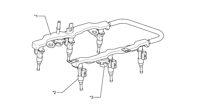
Text in Illustration *1 Fuel Delivery Pipe (for Port Injection) *2 Fuel Injector Assembly (for Port Injection) *3 Fuel Pressure Pulsation Damper Assembly - -
-
-
Fuel Delivery Pipe Sub-assembly (for Direct Injection)
-
A fuel delivery pipe sub-assembly (for direct injection), which is forged from iron, is used.
-
A fuel pressure sensor is installed on the fuel delivery pipe sub-assembly (for direct injection).
-
An injector clamp is provided for each area of the fuel delivery pipe where a fuel injector assembly (for direct injection) is installed. This clamp applies a constant spring force to the injector to prevent the injector from moving when the combustion pressure is applied to the injector while the engine is being started, during which the fuel pressure is low. As a result, the clamp increases the sealing performance of the injector, while reducing vibration and noise.
-
An O-ring and a backup ring are used on the fuel injector assembly (for direct injection). This reduces the transfer of activation sound of the fuel injector assembly (for direct injection) to improve quietness and ensure air tightness in the connecting portion.
-
Metal tapered seal is used on the connection portions between the fuel pressure sensor and the high pressure fuel pipe (No. 1 fuel pipe and fuel delivery pipe, No. 2 fuel pipe and fuel delivery pipe).
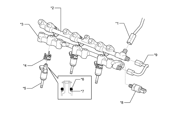
Text in Illustration *1 No. 1 Fuel Pipe *2 Fuel Delivery Pipe Sub-assembly RH (for Direct Injection) *3 Fuel Delivery Pipe Sub-assembly LH (for Direct Injection) *4 Injector Clamp *5 Fuel Injector Assembly (for Direct Injection) *6 O-ring *7 Backup Ring *8 Fuel Pressure Sensor *9 No. 2 Fuel Pipe - -
-
-
Fuel Injector Assembly (for Port Injection)
-
Compact and lightweight 12-hole injectors are used as fuel injectors for port injection.
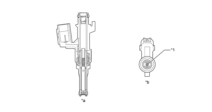
Text in Illustration *1 Injection Nozzle - - *a Cross Section *b Bottom Side View
-
-
Fuel Injector Assembly (for Direct Injection)
-
Slit-nozzle type injectors, which have 1 slit-shaped injection orifice, are used as fuel injectors for direct injection.
-
Each injector, based on signals from the ECM, measures the flow of high-pressure fuel. The fuel is injected as a fine-atomized mist in a fan shaped pattern, directly to the combustion chamber, via a slit type nozzle.
-
An insulator is used in the area in which the injector comes in contact with the cylinder head, and a Teflon shaft seal is used to seal the injector against the combustion pressure in the cylinders. This is conducted in order to reduce vibration and noise and to enhance sealing performance.
-
Each nozzle tip is coated to reduce the adhesion of deposits.
-
The injectors are actuated by the EDU using high voltage and constant-current control based on instructions from the ECM. This control allows the injectors to inject high-pressure fuel in a short amount of time.
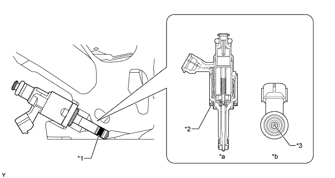
Text in Illustration *1 Teflon Shaft Seal *2 Insulator *3 Injection Nozzle - - *a Cross Section *b Bottom Side View
-
-
Solenoid Valve Assembly
-
The solenoid valve assembly is installed in the fuel pipe on the return side in order to return fuel to the fuel tank assembly by opening the valve in accordance with a signal from the ECM.
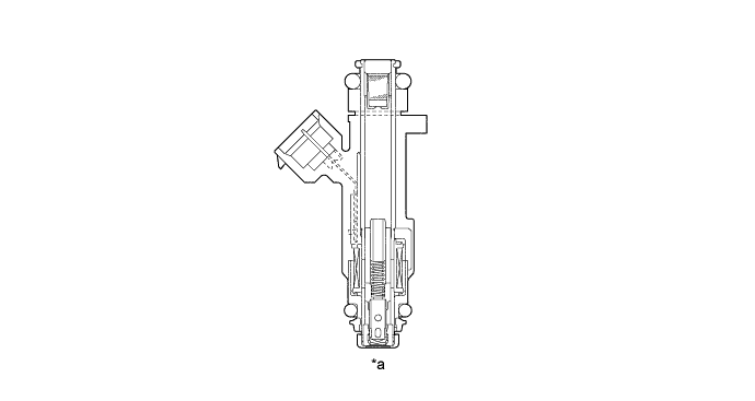
Text in Illustration *a Cross Section - -
-
-
Fuel Tank Assembly
-
A multi-layer plastic fuel tank is used. The multiplex layered plastic fuel tank consists of 6 layers of 4 types of materials, and one of those is a recyclable material to address environmental concerns.
-
A fuel drain mark has been provided at the lowest position of the fuel tank assembly. When dismantling (scrapping) the vehicle, drain fuel by drilling a hole at the drain mark.
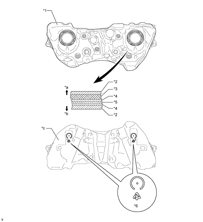
Text in Illustration *1 Fuel Tank Assembly *2 High Density Polyethylene (HDPE) *3 Regrind Material *4 Adhesive *5 Ethylene Vinyl Alcohol Copolymer (EVOH) *6 Fuel Drain Mark *a Fuel Tank Outside *b Fuel Tank Inside *c Bottom Side View - - -
The fuel tank uses a saddle shape to allow the propeller shaft to pass under the center portion of the tank. Also, a jet pump is used to transfer the fuel from the side of the tank without the fuel pump to the side with the fuel pump.
-
A fuel tank with such a shape tends to cause fuel to be present in both chamber A and chamber B when the fuel level is low. This stops the fuel in chamber B from being pumped out. To prevent this from occurring, a jet pump has been provided to transfer the fuel from chamber B to chamber A.
-
This is accomplished by utilizing the flow of the fuel through the jet pump, so that the pressure difference, which is created by the fuel as it passes through the venturi, is used to suck the fuel out of chamber B and send it to chamber A.
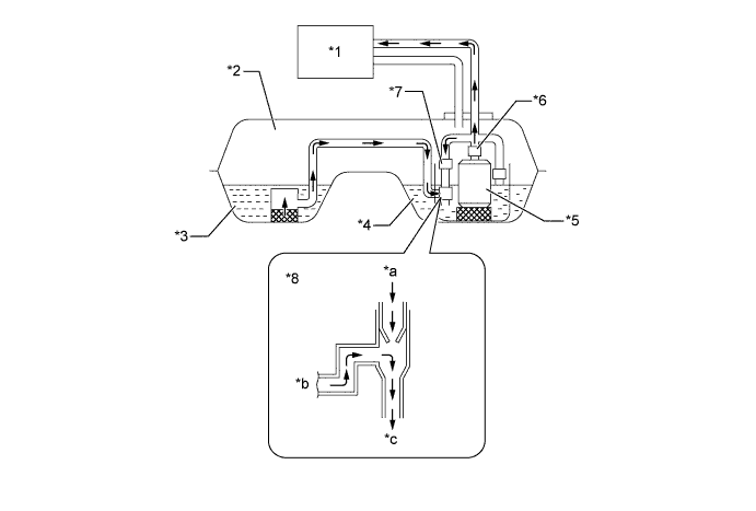
Text in Illustration *1 Engine *2 Fuel Tank Assembly *3 Chamber B *4 Chamber A *5 Fuel Pump *6 Fuel Filter Assembly *7 Fuel Main Valve Assembly *8 Jet Pump *a From Fuel Pump (Return) *b From Chamber B *c To Chamber A - -
-
-
-
OPERATION
-
Fuel Pump Assembly (for High Pressure)
-
During the intake portion of the pump cycle, the spill control valve is opened, and the pump plunger (piston) is moved downward by spring force. This allows fuel to be drawn into the cylinder of the pump. If the spill control valve has not been closed yet, when the cam forces the plunger to move upward, the fuel in the pump cylinder (this fuel is not pressurized) will be pushed back to the pump inlet (fuel tank side).
-
In order to close the spill control valve as the piston is moving upward, the ECM sends a signal to the valve via the EDU. When the spill control valve is closed and the plunger is moving upward, the pressure in the pump cylinder will rise. As this pressure rises above 60 kPa (or the pressure of the delivery pipe, whichever is higher), the fuel will begin to flow to the fuel delivery pipe sub-assembly (for direct injection). The ECM calculates the target fuel pressure based on driving conditions. The ECM controls the pressure by operating the spill control valve via the EDU. The timing and duration of the spill control valve closing are varied to cause the pump pressure to meet the target pressure.
-
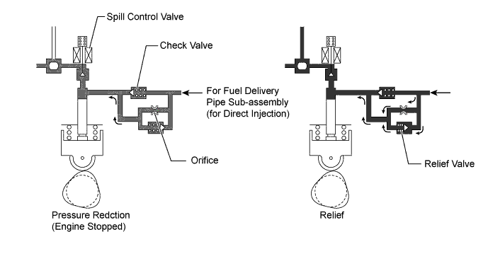
The relief valve opens and leaks fuel when a high pressure fuel part malfunctions to suppress the fuel pressure to a level within the pressure resistance level of the fuel system.
-
Fuel pressure is reduced by the orifice when the engine is stopped, thus improving fuel pressure control performance.
-
-
Fuel Return System
-
When the fuel temperature or fuel pressure exceeds the predetermined level due to vehicle driving conditions, fuel is returned to the fuel tank assembly by operating the solenoid valve assembly in accordance with a signal from the ECM, thus preventing fuel evaporation.
-
A fuel main valve assembly (return) is provided in the fuel pump assembly (for low-pressure) to maintain appropriate fuel pressure in the return pipe.
-
-