LIGHTING SYSTEM
-
FUNCTION OF MAIN COMPONENTS
-
Daytime Running Light System
Component Function Headlight Assembly Daytime Running Lights The Light Emitting Diode (LED) light illuminates. Main Body ECU (Multiplex Network Body ECU) The main body ECU (multiplex network body ECU) receives various signals and illuminates the daytime running lights via headlight light control ECU assembly. Headlight Light Control ECU Assembly LH
-
The headlight light control ECU assembly LH receives the daytime running light on signal from main body ECU (multiplex network body ECU).
-
The headlight light control ECU assembly LH turn the LH side daytime running light on.
-
Then the headlight light control ECU assembly LH sends these signals to the headlight light control ECU assembly RH.
Headlight Light Control ECU Assembly RH The headlight light control ECU assembly RH turn the RH side daytime running light on. Headlight Dimmer Switch Assembly Light Control Switch The light control switch outputs a light control signal and transmits it to the main body ECU (multiplex network body ECU). -
-
Light Emitting Diode (LED) Headlight System
Component Function Headlight Dimmer Switch Assembly Light Control Switch The light control switch transmits a head position signal to the main body ECU (multiplex network body ECU). Main Body ECU (Multiplex Network Body ECU) The main body ECU (multiplex network body ECU) receives the Head position signal from the light control switch and transmits a signal to the headlight light control ECU assembly LH/RH. Headlight Assembly Headlight Light Control ECU Assembly LH
-
The headlight light control ECU assembly LH receives the headlight on signal from main body ECU (multiplex network body ECU).
-
The headlight light control ECU assembly LH turn the LH side Light Emitting Diode for headlight on.
-
Then the headlight light control ECU assembly LH sends the signal to the headlight light control ECU assembly RH.
Headlight Light Control ECU Assembly RH The headlight light control ECU assembly RH turn the RH side Light Emitting Diode (LED) for headlight on. Combination Meter Assembly Taillight Indicator Light The taillight indicator lights up to inform the driver when the taillights turn on. Master Warning Light The master warning light blinks to inform the driver when the headlight light control ECU assembly LH detects malfunctions in this system. Multi-information Display The multi-information display displays a warning message to inform the driver when the headlight light control ECU assembly LH detects a malfunction in this system. -
-
Intelligent Adaptive Front-lighting System (AFS)
Component Function Headlight Assembly Headlight Light Control ECU Assembly LH
-
The headlight light control ECU assembly LH receives the various signals calculates the target lighting angle, and actuates the headlight swivel motor LH.
-
The headlight light control ECU assembly LH sends these signals to the headlight light control ECU assembly RH.
Headlight Light Control ECU Assembly RH The headlight light control ECU assembly LH receives these signals and actuates the headlight swivel motor RH. Headlight Swivel Motor LH/RH Driven by the headlight light control ECU assembly LH/RH and headlight swivel motor moves the low beam headlight left or right to the angle calculated by the headlight light control ECU assembly LH. Steering Sensor The steering sensor outputs the steering angle. Main Body ECU (Multiplex Network Body ECU) The main body ECU (multiplex network body ECU) receives a head position signal from the head light dimmer switch and transmits it to the headlight light control ECU assembly LH. Skid Control ECU Assembly The skid control ECU assembly transmits the signals of the speed sensors to the headlight light control ECU assembly LH. Headlight Dimmer Switch Assembly Light Control Switch The light control switch transmits a HEAD position signal to the main body ECU (multiplex network body ECU). Combination Meter Assembly AFS OFF Indicator Light
-
The AFS OFF indicator light lights up when the AFS control is stopped by the multi-information display.
-
The AFS OFF indicator light flashes when the headlight light control ECU assembly LH detects a malfunction.
Multi-information Display
-
The multi-information display displays a warning message to inform the driver when the headlight light control ECU assembly LH detects a malfunction in this system.
-
The combination meter assembly (multi-information display) outputs an AFS OFF signal and transmits it to the headlight light control ECU assembly LH.
-
-
Automatic Headlight Beam Level Control System
Component Function Headlight Light Control ECU Assembly LH
-
The headlight light control ECU assembly detects changes of vehicle movement based on the rear height control sensor sub-assembly LH and speed signal.
-
The headlight light control ECU assembly LH outputs control signals to the headlight leveling motor LH*1 or headlight swivel motor LH*2 based on the detected value.
-
The headlight light control ECU assembly LH outputs control signals to the headlight light control ECU assembly RH.
-
This ECU provides a fail safe function.
Headlight Light Control ECU Assembly RH The headlight light control ECU assembly RH outputs control signals to the headlight leveling motor RH*1 or headlight swivel motor RH*2 based on the signals from headlight light control ECU assembly LH. Headlight Assembly Headlight Leveling Motor LH/RH*1 Driven by the headlight light control ECU assembly LH/RH and headlight leveling motor moves the low beam headlight to vary its angle. Headlight Swivel Motor LH/RH*2 Driven by the headlight light control ECU assembly LH/RH and headlight swivel motor moves the low beam headlight to vary its angle. Main Body ECU (Multiplex Network Body ECU) The main body ECU (multiplex network body ECU) receives a head position signal from the headlight dimmer switch and transmits it to the headlight light control ECU assembly LH. Skid Control ECU Assembly The skid control ECU assembly outputs information about the vehicle speed. This information is used by the headlight light control ECU assembly LH to control automatic headlight beam level control system. Headlight Dimmer Switch Assembly Light Control Switch The headlight dimmer switch assembly transmits the light control switch position signal to the main body ECU. Rear Height Control Sensor Sub-assembly LH The rear height control sensor sub-assembly LH detects vehicle movement and transmits a signal to the headlight light control ECU assembly LH. Combination Meter Assembly Multi-information Display The multi-information display displays a warning message to inform the driver when the headlight light control ECU assembly LH detects a malfunction in this system.
-
*1: Models without AFS
-
*2: Models with AFS
-
-
Automatic Light Control System
Component Function Light Relay The light relay supplies power to the headlight light control ECU assembly LH/RH. Integration Relay The integration relay supplies power to the taillights and license plate lights. Headlight Light Control ECU Assembly LH/RH The headlight light control ECU assembly LH/RH supplies power to the clearance lights, side marker lights and headlights. Certification ECU (Smart Key ECU Assembly) The certification ECU receives the engine switch push signal and transmits it to the main body ECU. Main Body ECU (Multiplex Network Body ECU) The main body ECU (multiplex network body ECU) receives various signals and controls the automatic light control system. Automatic Light Control Sensor The automatic light control sensor detects the ambient light level and transmits it to the main body ECU. Headlight Dimmer Switch Assembly Light Control Switch The headlight dimmer switch assembly transmits the AUTO position signal to the main body ECU. Combination Meter Assembly Taillight Indicator Light The taillight indicator light lights up to inform the driver when the taillights turn on. -
Light Auto Turn-off System
Component Function Light Relay The light relay supplies power to the headlight light control ECU assembly LH/RH. Integration Relay (TAIL Relay) The TAIL relay supplies power to the taillights, clearance lights and license plate lights. Headlight Light Control ECU Assembly LH/RH The headlight light control ECU assembly LH/RH supplies power to the clearance lights, side marker lights and headlights. Main Body ECU (Multiplex Network Body ECU) The main body ECU (multiplex network body ECU) receives various signals and controls the light auto turn-off system. Courtesy Light Switch Assemblies Front (LH, RH), Rear (LH, RH) The courtesy light switch assembly detects whether a door is open or closed and transmits a signal to the main body ECU (multiplex network body ECU). Door Unlock Detection Switches Front (LH, RH), Rear (LH, RH) The door unlock detection switch detects whether a door is locked or unlocked and transmits a signal to the main body ECU (multiplex network body ECU). Door Control Receiver The door control receiver receives the ID code from the transmitter in the actuation area and transmits it to the main body ECU (multiplex network body ECU). Certification ECU (Smart Key ECU Assembly)
-
The certification ECU (smart key ECU assembly) judges and certifies the ID code from the door control receiver.
-
The certification ECU (smart key ECU assembly) receives the engine switch push signal and transmits it to the main body ECU (multiplex network body ECU).
-
-
Door Mirror Foot Light System
Component Function Door Lock Control Switch Driver, Front Passenger The door lock control switch outputs the lock/unlock signal to the main body ECU (multiplex network body ECU) or multiplex network master switch assembly. Certification ECU (Smart Key ECU Assembly) The certification ECU (smart key ECU assembly) judges and certifies the ID code. Main Body ECU (Multiplex Network Body ECU) The main body ECU (multiplex network body ECU) receives various signals and transmits them to the multiplex network door ECUs. Multiplex Network Door ECUs (LH, RH) The multiplex network door ECUs receive various signals and illuminates the door mirror foot lights. Power Management Control ECU The power management control ECU receives the shift position signals from the shift lever position sensor and transmits them to the main body ECU (multiplex network body ECU). Courtesy Light Switch Assemblies Front (LH, RH), Rear (LH, RH) The courtesy light switch assembly detects whether a door is open or closed and transmits a signal to the main body ECU (multiplex network body ECU). Door Unlock Detection Switches Front (LH, RH), Rear (LH, RH) The door unlock detection switch detects the whether a door is locked or unlocked and transmits a signal to the main body ECU (multiplex network body ECU). Multiplex Network Master Switch Assembly The multiplex network master switch assembly sends the driver side door lock switch signal to the main body ECU (multiplex network body ECU). -
Illumination System
Component Function Certification ECU (Smart Key ECU Assembly) The certification ECU (smart key ECU assembly) judges and certifies the ID code from the door control receiver. Main Body ECU (Multiplex Network Body ECU) The main body ECU (multiplex network body ECU) receives various signals and illuminates the clearance lights, taillights and license plate lights. Door Control Receiver The door control receiver receives the ID code from the electrical key transmitter sub-assembly in the actuation area and transmits it to the main body ECU (multiplex network body ECU). Headlight Assemblies (LH, RH) Clearance Lights The Light Emitting Diode (LED) light illuminates. Rear Combination Light Assemblies (LH, RH) Taillights The Light Emitting Diode (LED) light illuminates. Rear Light Assemblies (LH, RH) Automatic Light Control Sensor Assembly The automatic light control sensor assembly detects the ambient light level and transmits them to the main body ECU (multiplex network body ECU). -
Emergency Brake Signal System
Component Function Skid Control ECU Assembly Manages signals from each sensor and sends the operation signal of the emergency brake signal to the integration relay. Yawrate Sensor Detects vehicle acceleration and sends the information to the skid control ECU. Speed Sensors Detects the wheel speed of each of the 4 wheels. Stop Light Switch Assembly Detects the brake pedal depressing signal. Multi-media Module Receiver Assembly Hazard Warning Signal Switch Sends the operation signal of the hazard warning light to the combination meter assembly. Stop Light Blinks when the system is controlled. Combination Meter Assembly Controls the hazard warning lights. -
Automatic High Beam (AHB) System
Component Function Headlight Light Control ECU Assembly LH
-
The headlight light control ECU assembly LH receives the lights of oncoming vehicles, preceding vehicles and other lights signals from the froward recognition camera via CAN communication.
-
The headlight light control ECU assembly LH receives various signals and controls the automatic high beam system.
-
When the high beam headlight is on, the headlight light control ECU assembly LH sends high beam actuation signals to the headlight light control ECU RH via CAN communication.
Forward Recognition Camera
-
The forward recognition camera identifies the lights of oncoming vehicles, preceding vehicles and other lights from the picture information of its camera sensor.
-
Then, the sensor sends these signals to the headlight light control ECU assembly LH via CAN communication.
-
Transmits an operation signal to the camera heater.*1
Camera Heater (Forward Recognition Hood with Heater Sub-assembly)*1 Heats the sheet heater in accordance with the signals from the forward recognition camera. Power Management Control ECU The power management control ECU receives the shift position signals from the shift lever position sensor and transmits a signal to the headlight light control ECU assembly LH. Main Body ECU (Multiplex Network Body ECU) The main body ECU (multiplex network body ECU) receives the light control switch position from headlight dimmer switch assembly. Headlight Solenoid*2 The headlight solenoid rotates the shade, which is built into headlight assembly, down to allow use of the lower illumination area, thus increasing the illumination area when the high beam request signal is received. Skid Control ECU Assembly The skid control ECU assembly outputs information about the speed of the wheel. This information is used by the automatic high beam control to control switching between the high beams and low beams of the automatic high beam system. Shift Lever Position Sensor The shift lever position sensor outputs signals to indicate the position of the shift lever. Based on these signals, the power management control ECU determines the intended shift condition and direction of vehicle movement. Headlight Dimmer Switch Assembly Light Control Switch The light control switch transmits an AUTO position signal to the main body ECU (multiplex network body ECU). Dimmer Switch The dimmer switch transmits high beam position signal to the main body ECU (multiplex network body ECU). Integration Control and Panel Assembly Automatic High Beam Switch The automatic high beam switch outputs the automatic high beam system on or off signal to the headlight light control ECU assembly LH. Automatic Light Control Sensor The automatic light control sensor detects the ambient light level and transmits a signal to the main body ECU (multiplex network body ECU). Yawrate Sensor The yawrate sensor outputs the yaw rate information. Combination Meter Assembly Automatic High Beam Indicator Light The automatic high beam indicator light illuminates to inform the driver when the automatic high beam system is activated. High Beam Indicator Light The high beam indicator light illuminates to inform the driver when the high beams are on. Multi-information Display
-
When the headlight dimmer switch is not in high beam position and the automatic high beam switch is on, then the multi-information display shows an advice message.
-
When the headlight light control ECU assembly LH detects a malfunction in the automatic high beam system, a warning message is displayed in the multi-information display to warn the driver.
-
*1: Models with camera heater
-
*2: Models with projector type headlight
-
-
Adaptive High-beam System (AHS)
Component Function Forward Recognition Camera
-
The forward recognition camera identifies the lights of oncoming vehicles, preceding vehicles and other lights from the picture information of its camera. Then, the sensor sends signals to the headlight light control ECU assembly LH via the CAN network.
-
Transmits an operation signal to the camera heater.*
Camera Heater (Forward Recognition Hood with Heater Sub-assembly)* Heats the sheet heater in accordance with the signals from the forward recognition camera. Headlight Light Control ECU Assembly LH
-
The adaptive high beam system turns on and off according to whether the integration control and panel assembly (AHS switch) is on or off.
-
The headlight light control ECU assembly LH receives the signals from forward recognition camera and other ECUs.
-
The headlight light control ECU assembly LH determines when to turn the hi beams or half shade beams on or off.
-
Then the headlight light control ECU assembly LH sends these signals to the headlight light control ECU assembly RH and swivel actuator.
Headlight Light Control ECU Assembly RH Controls the hi beams, lo beams and variable shade beams for the headlight on the right side according to the control status signal from the headlight light control ECU assembly LH. Headlight Leveling Motor LH/RH The headlight leveling motor controls the vertical light beam axis of the headlight. LED Light Control ECU LH/RH Illuminates, turns off or adjusts the LEDs used for the hi beams and variable shade beams according to signals from the headlight light control ECU assembly LH or the headlight light control ECU assembly RH. Rear Height Control Sensor Sub-assembly LH The rear height control sensor sub-assembly LH detects vehicle movement and transmits a signal to the headlight light control ECU assembly LH. Yawrate Sensor The yawrate sensor sends a yaw rate signal via CAN communication. Speed Sensor Detects the vehicle speed and transmits it to the skid control ECU assembly. Skid Control ECU Assembly The skid control ECU assembly outputs information about the vehicle speed. This information is used by the headlight light control ECU assembly LH to control Adaptive High-beam System (AHS). Headlight Dimmer Switch Assembly The headlight dimmer switch assembly transmits the auto position signal and the hi beam position signal to the main body ECU. Integration Control and Panel Assembly (AHS Switch) Outputs the on and off switching signal of the Adaptive Highbeam System (AHS) to the headlight light control ECU assembly LH. Automatic Light Control Sensor The automatic light control sensor detects the ambient light level. Combination Meter Assembly
-
Receives signals from the headlight light control ECU assembly LH and illuminates or turns off the adaptive high-beam indicator lights.
-
If a system malfunction display request signal is received, this component displays a warning message on the multiinformation display.
Main Body ECU (Multiplex Network Body ECU) Sends the headlight dimmer switch assembly and automatic light control sensor signals to the main body ECU and headlight light control ECU assembly LH. Shift Lever Position Sensor The shift lever position sensor outputs the shift position signal to the power management control ECU. Power Management Control ECU The power management control ECU receives the shift position signals from the shift lever position sensor and transmits a signal to the headlight light control ECU assembly LH.
-
*: Models with camera heater
-
-
-
OPERATING CONDITION
-
Daytime Running Light System
-
The daytime running lights illuminate when the following conditions are met:
-
The power switch is on (READY).
-
Light control switch OFF or AUTO position (when taillight is not being controlled by the automatic light control).
-
The parking brake is off.
-
-
-
Intelligent Adaptive Front-lighting System (AFS)
-
The intelligent AFS will operate when all of the following conditions are met:
-
The power switch is on (READY).
-
The vehicle is moving forward at a speed above or equal to 10 km/h (6 mph) but below 30 km/h (19 mph).*1
-
The vehicle is moving forward at a speed of 30 km/h (19 mph) or more.*2
-
Steering angle is 27° or more.*1
-
Steering angle is 7.5° or more.*2
-
The headlights are operating in low beam.
-
The intelligent AFS is on.
Tech Tips
*1: Low speed control is performed.
*2: Medium-to-high speed control is performed.
-
-
-
Automatic High Beam System
-
The automatic high beam system operates as follows:
Condition Details Active When all of the following conditions are met, the automatic high beam system is activated and the automatic high beam indicator light turns on:
-
The power switch is on (IG).
-
The headlight dimmer switch assembly is in the AUTO or HEAD position and high beam position.
-
automatic high beam switch is on.
High Beams on When all of the following conditions are met, the automatic high beam system turns on the high beams after a short delay:
-
Vehicle speed is more than approx. 30 km/h (19 mph).
-
The area in front of the vehicle is dark (the automatic light control sensor outputs the night mode signal).
-
No oncoming vehicles are present with the headlights on.
-
No preceding vehicles are present with the taillights on.
-
Few streetlights are present along the street ahead.
High Beams off When any of the following conditions are met, the automatic high beam system turns off the high beams after a short delay:
-
Vehicle speed is less than approx. 25 km/h (16 mph).
-
The area in front of the vehicle is not dark.
-
An oncoming vehicle with headlights on is detected.
-
A preceding vehicle with taillights on is detected.
-
Several streetlights are present along the street ahead.
-
-
-
Light Auto Turn-off System
-
The light auto turn-off system operates as follows:
Condition Details Driver Door-linked When all of the following conditions are met, the exterior lights automatically turn off:
-
The power switch is turned off or on (ACC).
-
The driver door is closed and then opened.
-
The headlight dimmer switch assembly is in the TAIL position.
Follow Me Home When approx. 30 seconds elapse after all of the following conditions are met, the head lights turn off:
-
The power switch is turned off.
-
All doors are closed.
-
The headlight dimmer switch assembly is in the pass position, then neutral position.
-
-
-
Door Mirror Foot Light System
-
The door mirror foot light system operates as follows:
Condition Details Actuation Area-linked When all of the following conditions are met, the door mirror lights automatically turn on:
-
The power switch is off.
-
All doors are closed.
-
The electrical key transmitter sub-assembly is detected in the actuation area.
When the following condition is met, the door mirror lights automatically turn off:
-
The electrical key transmitter sub-assembly is not detected in the actuation area.
Door Unlock-linked When all of the following conditions are met, the door mirror lights automatically turn on:
-
The power switch is off.
-
Any door is unlocked.
-
All doors are closed.
Door Lock-linked When one of the following conditions is met, the door mirror lights automatically turn off:
-
All doors are locked.
-
All doors are closed.
-
A door lock control switch outputs the lock signal.
Door-linked When the following condition is met, the door mirror lights automatically turn on:
-
The power switch is off.
-
Any door is opened and then closed.
Delay When approx. 15 seconds elapse after one of the following conditions is met, the door mirror lights turn off:
-
An actuation area-linked function is used.
-
The door unlock-linked function is activated.
-
Any door is opened and then closed.
-
-
-
Emergency Brake Signal
-
The activating and deactivating conditions for the emergency brake signal are as shown in the following table:
Condition Details Emergency Brake Signal Operating Conditions When all of the following conditions are met, the emergency brake signal starts operating:
-
Vehicle speed is above 55 km/h (35 mph).
-
Driver is depressing the brake pedal.
-
Emergency braking is detected from the vehicle deceleration.
Emergency Brake Signal Ending Conditions When any of the following conditions is met, the emergency brake signal stops operating:
-
Driver has released the brake pedal.
-
Emergency braking is no longer detected from the vehicle deceleration.
-
Driver has pressed the hazard warning signal switch.
-
-
-
Illumination System
-
The Illumination system operates as follows:
Condition Details Door Unlock-linked When all of the following conditions are met, the clearance lights and taillights automatically turn on:
-
The power switch is off.
-
Any door is unlocked.
-
All doors are closed.
Door Lock-linked When one of the following conditions is met, the clearance lights and taillights automatically turn off:
-
All doors are locked.
-
All doors are closed.
-
-
-
Adaptive High-beam System (AHS)
-
The Adaptive High-beam System (AHS) operates as follows:
Condition Details System Activation When all of the following conditions are met, the Adaptive High-beam System (AHS) is activated and the adaptive high beam indicator light turns on:
-
The power switch is on (IG).
-
The headlight dimmer switch assembly is in the AUTO position or HEAD position and hi beam position.
-
The automatic light control sensor outputs the night mode signal.
-
The AHS switch is on.
Hi Beam Headlight On When all of the following conditions are met, the Adaptive High-beam System (AHS) turns on the hi beam headlights after a short delay:
-
Vehicle speed is more than approximately 15 km/h (9 mph)*1 or 60 km/h (37 mph)*2.
-
Oncoming vehicles with the headlights on are not detected.
-
Preceding vehicles with the taillights on are not detected.
-
Few streetlights are present along the street ahead and the area in front of the vehicle is dark.
Hi Beam Headlight Off (Lo Beam Headlight On) When any of the following conditions are met, the automatic system turns off the hi beam headlights after a short delay:
-
Vehicle speed is less than approximately 10 km/h (6 mph)*1 or 40 km/h (25 mph)*2.
-
Several streetlights are present along the street ahead and the area in front of the vehicle is not dark.
-
Many oncoming vehicles or preceding vehicles are detected in front of the vehicle.
-
The preceding vehicle is moving quickly and the vehicle is struck by glare from that vehicle.
Variable Shade Beam On When all of the following conditions are met, the variable shade beam turns on after a short delay:
-
Vehicle speed is less than approximately 15 km/h (9 mph)*1 or 60 km/h (37 mph)*2.
-
Several streetlights are present along the street ahead and the area in front of the vehicle is dark.
-
An oncoming vehicle with the headlights on can be detected.
-
A preceding vehicle with the taillights on can be detected.
-
*1: Except models for Europe
-
*2: Models for Europe
-
-
-
-
SYSTEM CONTROL
-
Intelligent AFS (Low Speed Control)
-
The headlight light control ECU assembly LH calculates the swivel angle from the steering angle, vehicle speed and drives the headlight swivel motor on the side facing into the turn to illuminate the road ahead during cornering.
Headlight Swivel Motor LH RH Driving Condition (LHD Models) Right Turn 0° Fixed 0° to 10° to Right Left Turn 0° to 20° to Left 0° Fixed Driving Condition (RHD Models) Right Turn 0° Fixed 0° to 20° to Right Left Turn 0° to 10° to Left 0° Fixed
-
-
Intelligent AFS (Medium-to-high Speed Control)
-
Based on the steering angle and vehicle speed, the headlight light control ECU assembly LH calculates the swivel angle of the low beam headlights so that the headlights can illuminate the position which the vehicle will reach after 3 seconds, and drives both headlight swivel motors to illuminate the road ahead during cornering.
Headlight Swivel Motor LH RH Driving Condition (LHD Models) Right Turn 0° to 5° to Right 0° to 10° to Right Left Turn 0° to 15° to Left 0° to 7.5° Left Driving Condition (RHD Models) Right Turn 0° to 7.5° to Right 0° to 15° to Right Left Turn 0° to 10° to Left 0° to 5° Left
-
-
Intelligent AFS (Initial Set Control)
-
When the power switch is on (READY), the headlight light control ECU assembly LH drives the headlight swivel motors, moves the headlight to the operation limit in the direction toward the vehicle center and then returns it to the proper position. In this way, the headlight light control ECU assembly LH determines the standard position of the headlight.
-
-
-
FUNCTION
-
Automatic High Beam System
-
When passing an oncoming vehicle:
-
The automatic high beam system turns off the high beams before an oncoming vehicle comes within approximately 800 m (2600 ft.).
-
When an oncoming vehicle passes out of camera sensor range, the automatic high beam system turns the high beams on after a short delay.
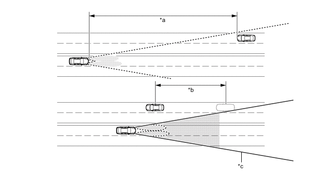
Text in Illustration *a Approx. 800 m (2600 ft.) *b Delay *c Camera Sensor Angle - - Tech Tips
-
The detection distance varies depending on detected objects.
-
The timing of turning on and off the high beams varies depending on the intensity of oncoming (and preceding) vehicle lights.
-
-
When passing a preceding vehicle:
-
When approaching a preceding vehicle, the automatic high beam system turns off the high beams approximately 600 m (1950 ft.) before reaching it.
-
When a preceding vehicle passes out of camera sensor range, the automatic high beam system turns the high beams on after a short delay.
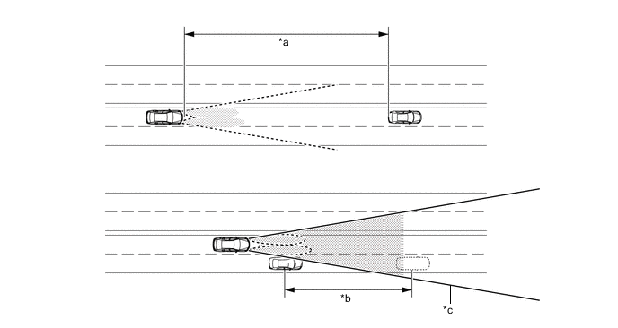
Text in Illustration *a Approx. 600 m (1950 ft.) *b Delay *c Camera Sensor Angle - - Tech Tips
The timing of turning on and off the high beams varies depending on the intensity of the preceding vehicle lights.
-
-
-
Adaptive High-beam System (AHS)
-
An Adaptive High-beam System (AHS), which detects preceding and oncoming vehicles and automatically switches between the hi beam, lo beam and variable shade beam headlights, has been provided depending on the model.
-
When the lo beam illumination conditions are met while the Adaptive High-beam System (AHS) is operating, the system changes light distribution for the lo beam headlights.
-
When the hi beam illumination conditions are met while the Adaptive High-beam System (AHS) is operating, the system illuminates the hi beam headlights in a light distribution mode appropriate for the vehicle speed.
-
The light distribution of the hi beam headlights has 3 different modes:
-
Town Mode
-
This extends illumination to the sides at low-speeds.
-
Normal Mode
-
This ensures brightness in front of the vehicle while extending illumination to the left and right sides at medium-speeds.
-
High-speed Mode
-
This provides superior visibility in front of the vehicle at high-speeds.
-
-
When the variable shade beam illumination conditions are met while the Adaptive High-beam System (AHS) is operating, the system illuminates, turns off or adjusts the light of the numerous LEDs arranged in the hi beam headlights to prevent glare from striking preceding and oncoming vehicles while illuminating other areas.
-
When the hi beam headlights are illuminated, the system estimates the corner angle in the direction of travel according to the steering wheel operation angle, etc., and operates electronic swivel control to illuminate in the direction of travel.
-
Light Distribution Control Function
-
The light distribution of the hi beam headlights can create a condition where the brightness and illumination range are optimized according to the vehicle speed.
Light Distribution Mode Control Description Vehicle Speed Town Mode (Except Models for Europe)
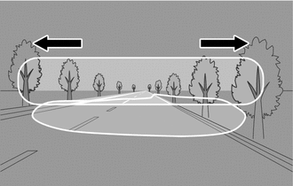
The illumination ranges to the left and right sides are expanded in consideration of visibility at low speeds. Furthermore, a brightness suitable for pedestrian visibility is achieved while glare is reduced for pedestrians. Also, illumination to the sides is reduced to suppress illumination which reaches the sides of the road and sidewalks. 15 km/h to 30 km/h (9 mph to 19 mph) Normal Mode
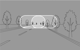
The necessary amount of light is spread to the left and right sides and light is distributed towards the center area for long-range visibility. 30 km/h to 80 km/h (19 mph to 50 mph)*1
60 km/h to 120 km/h (37 mph to 74 mph)*2
High-speed Mode
Light distribution is performed to narrow the illumination range, achieving even further long-range visibility in consideration of visibility at high-speeds. Also, outermost hi beams are illuminated. 80 km/h (50 mph) or more*1
120 km/h (74 mph) or more*2
Manual Hi Beam
Illuminates in the same way as normal mode. - *1: Except models for Europe
*2: Models for Europe
-
-
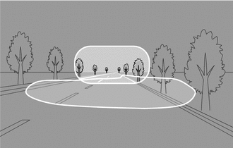
Shade Control Function
-
The illumination of LEDs is controlled according to the positions of preceding and oncoming vehicles to shade multiple areas as needed, ensuring night-time visibility while reducing glare.
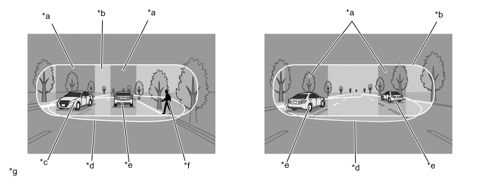
Text in Illustration *a Hi Beam Headlight Shade Area *b Hi Beam Headlight Illuminated Area *c Oncoming Vehicle *d Lo Beam Headlight Illuminated Area *e Preceding Vehicle *f Pedestrian *g The illustrations shown examples only. - -
-
-
Electronic Swivel Control
-
When driving around curves with the hi beam headlights illuminated, this function variably controls the LED brightness to illuminate in the direction of travel, ensuring visibility in the direction of travel.
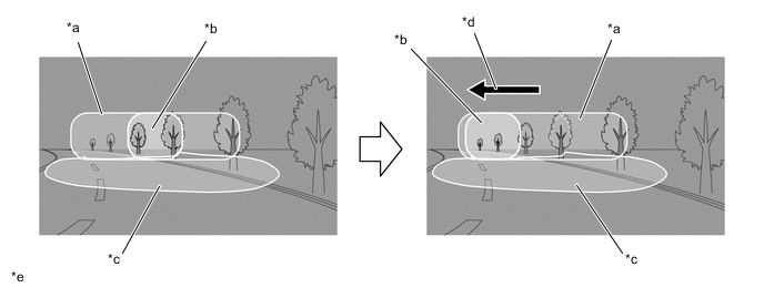
Text in Illustration *a Hi Beam Headlight Illuminated Area *b High Brightness Area *c Lo Beam Headlight Illuminated Area *d Travel the high brightness area to the direction of the curve. *e The illustrations shown examples only. - -
-
-
Lo Beam Headlight Cut Line Tilt Control Function
-
The headlight leveling motor built into the headlight assembly is operated according to the position of the preceding vehicle detected by the forward recognition camera. As a result, the illumination area of the lo beam headlights is optimally controlled to illuminate the longest range possible while reducing glare.
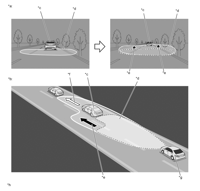
Text in Illustration *a The low beam headlight illuminated area image (view from the driver). *b The low beam headlight illuminated area image (bird-eye view). *c Lo Beam Headlight Illuminated Area *d Lo Beam Illuminated Area *e Movement of the Lo Beam Illuminated Area *f Movement of the Preceding Vehicle *g Own Vehicle *h The illustrations shown an example only.
-
-
Adaptive High-beam System (AHS) Manual Switching Operation
-
The headlights can be manually switched between the lo and hi beams while the headlights are controlled by the Adaptive High-beam System (AHS) by performing the following operation.
-
When switching from the hi beams or variable shade beam illumination to the lo beams, change the dimmer switch of the light control switch to the lo beam position. This operation cancels the Adaptive High-beam System (AHS) and illuminates the lo beams.*1
-
When switching from the lo beams to the hi beams, turn the AHS switch off. This operation turns the Adaptive High-beam System (AHS) off and illuminates the hi beams.*2
Tech Tips
*1: When using the Adaptive High-beam System (AHS) again, operate the dimmer switch to the hi beam position.
*2: When using the Adaptive High-beam System (AHS) again, turn the AHS switch on.
-
-
Combination Meter Assembly
-
When the Adaptive High-beam System (AHS) is activated, the combination meter assembly informs the driver by illuminating the adaptive high-beam indicator light.
-
When the hi beam headlights are on, the combination meter assembly informs the driver by illuminating the hi beam headlight indicator light.
-
If malfunctions occur in the AHS, the combination meter assembly warns the driver by indicating a message on the multi-information display, sounding the buzzer and illuminates the master warning light when receiving signals from the headlight light control ECU assembly LH.
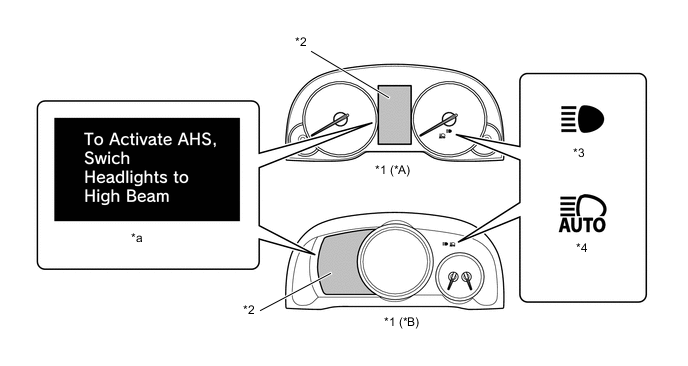
Text in Illustration *A Except F SPORT *B F SPORT *1 Combination Meter Assembly *2 Multi-information Display *3 Hi Beam Indicator Light *4 Adaptive High-beam Indicator Light *a Advisory Display - -
-
-
-
-
CONSTRUCTION
-
Projector Type Headlight Assembly
-
Bi-function
-
If the low beam is selected, the lower illumination area of the LED is blocked by a shade and only the upper illumination area is used.
-
If the high beam is selected, the headlight solenoid rotates the shade down to allow use of the lower illumination area, thus increasing the illumination area and improving visibility when the high beam is selected.
-
The bi-function is activated by the headlight light control ECU assembly LH/RH. The headlight light control ECU assembly activates the built-in headlight solenoid to slide the shade down.
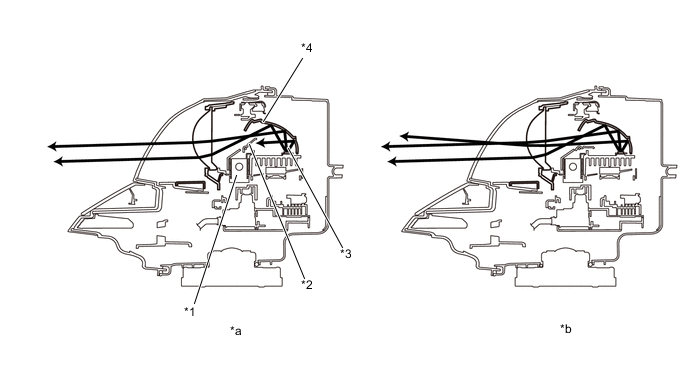
Text in Illustration *1 Headlight Solenoid *2 Shade *3 LED *4 Reflector *a Low Beam *b High Beam
-
-
-
Triple Projector Type Headlight Assembly
-
LEDs are arranged behind a uniquely shaped lens used for the lo and hi beam headlights in the headlight assembly.
Text in Illustration *1 Lens *2 LED *3 Reflector - - *a Low Beam Headlight *b High Beam Headlight *c The illustration is shown an example only. - - -
On models with Adaptive High-beam System (AHS), 11 LEDs are included in the hi beam portion, creating the variable shade beam of the Adaptive High-beam System (AHS). Also, when the hi beams are illuminated during high-speed driving, the intensities of the outermost areas of the hi beam headlights are increased.
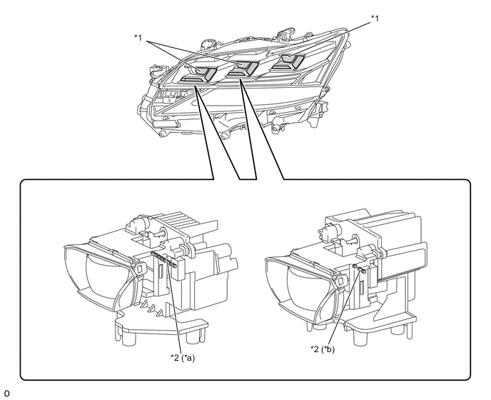
Text in Illustration *1 Hi Beam for AHS *2 LEDs *a 8 LEDs *b 3 LEDs
-
-
Headlight Light Control ECU assembly and LED Light Control ECU
-
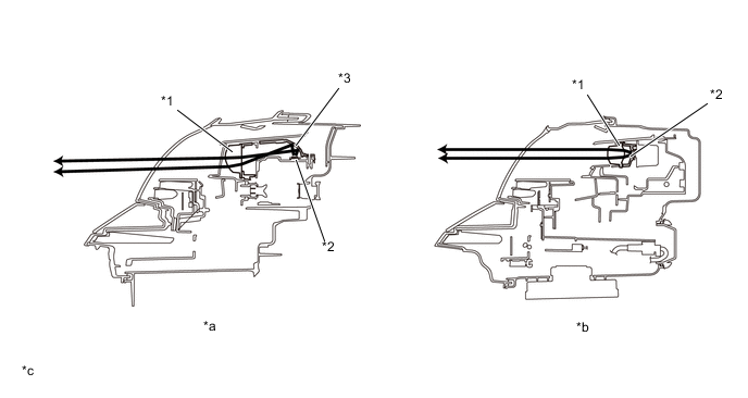
The headlight light control ECU assembly LH/RH illuminates the LED used as a light source for the low beam headlights and high beam headlights.
-
When the low beam headlights or high beam headlights are illuminated, a constant current flows to the LED to instantly stabilize the headlights.
-
Also, changes in the LED current due to fluctuations in the voltage are reduced to prevent the lights from flickering.
-
The LED light control ECU illuminates the LED used as a high beam source for the Adaptive High beam System (AHS).
-
Also, changes in the each LED current for control the axes of the hi-beam headlight.
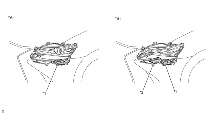
Text in Illustration *A Models with Projector Type Headlight Assembly *B Models with Triple Projector Type Headlight Assembly *1 Headlight Light Control ECU Assembly LH/RH *2 LED Light Control ECU *a The illustration is shown an example only. - -
-
-
-
FAIL-SAFE
-
Combination Meter Assembly
-
When a malfunction is detected in the Adaptive High-beam System (AHS), Automatic High Beam (AHB) system, intelligent Adaptive Front-lighting System (AFS), automatic headlight beam level control system and LED headlight system, the headlight light control ECU assembly LH performs fail-safe operation and outputs a warning request signal to the combination meter assembly.
-
In accordance with this signal, a warning message is displayed on the multi-information display in the combination meter assembly, the master warning light illuminates and the buzzer sounds. Furthermore, refer to the repair manual for details regarding fail-safe operation.
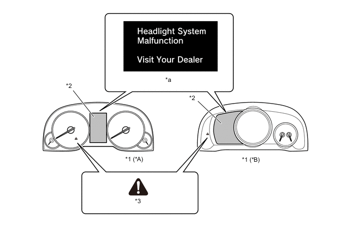
Text in Illustration *A Except F SPORT *B F SPORT *1 Combination Meter Assembly *2 Multi-information Display *3 Master Warning Light - - *a Warning Message - -
-
-