LEXUS PARKING ASSIST-SENSOR SYSTEM
-
FUNCTION OF MAIN COMPONENTS
-
The components have the following functions:
Component Function No. 1 Ultrasonic Sensors Detect the distance between the vehicle and the obstacle. Clearance Warning ECU Assembly Judges the approximate distance between the vehicle and obstacle based on the signals from the ultrasonic sensors and sends the buzzer signal to the clearance warning buzzer. No. 1 Clearance Warning Buzzer Sounds intermittently to inform the driver that the clearance warning ECU assembly has detected an obstacle within the prescribed range. Back Sonar or Clearance Sonar Switch Assembly The Lexus parking assist-sensor system can be turned on or off by operating this switch. Combination Meter Assembly
-
Transmits received vehicle speed signals to the clearance warning ECU assembly
-
Displays the detection location on the multi-information display when an obstacle is detected.
Multi-media Module Receiver Assembly Sends information to the multi display when obstacles are detected. Multi-display*1 Displays signals from the multi-media module receiver assembly on the screen. Accessory Meter Assembly*2 Power Management Control ECU Sends shift position information to the Clearance Warning ECU Assembly. Central Gateway ECU Transmits the signal between the CAN communication bus.
-
*1: Models with 8-inch display
-
*2: Models with 12.3-inch display
-
-
-
OPERATING CONDITION
-
The operating condition of each ultrasonic sensor differs in accordance with its installed position as shown in the table below:
Installation Position Operating Condition Front Corner
-
Power switch is on (IG).
-
Back sonar or clearance sonar switch assembly is on.
-
Shift lever is in anything except P.
-
Vehicle speed is approximately 10 km/h (6 mph) or less.
Front Center
-
Power switch is on (IG).
-
Back sonar or clearance sonar switch assembly is on.
-
Shift lever is in anything except P and R.
-
Vehicle speed is approximately 10 km/h (6 mph) or less.
Rear Center or Corner
-
Power switch is on (IG).
-
Back sonar or clearance sonar switch assembly is on.
-
Shift lever is in R.
-
-
-
CONSTRUCTION
-
No. 1 Ultrasonic Sensor (Front Center)
-
The ultrasonic sensor consists of a circuit portion and a microphone that transmits and receives ultrasonic waves.
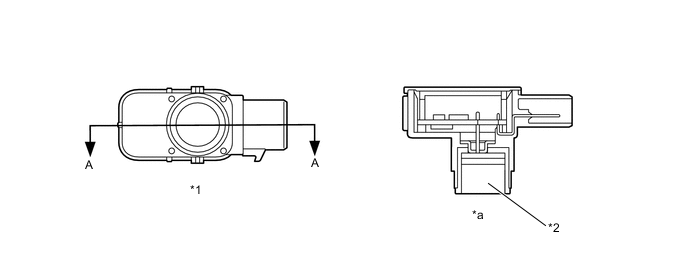
Text in Illustration *1 No. 1 Ultrasonic Sensor *2 Microphone *a A - A Cross Section - -
-
-
No. 1 Ultrasonic Sensor (Front Corner, Rear Center and Rear Corner)
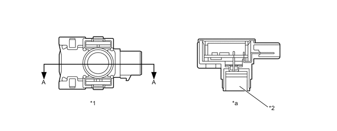
Text in Illustration *1 No. 1 Ultrasonic Sensor *2 Microphone *a A - A Cross Section - - -
No. 1 Clearance Warning Buzzer
-
When the ultrasonic sensor transmits ultrasonic waves and receives the reflected waves from an obstacle, the buzzer sounds in stages in accordance with the distance to the obstacle.

-
-
-
OPERATION
-
The on and off times of the clearance warning buzzer assembly vary as shown in the table below, depending on the distance between the obstacle and the ultrasonic sensor.
Front Ultrasonic Sensor - Obstacle Distance [mm (in.)] Off Time (ms) On Time (ms) Detection Area A B Ultrasonic Sensor Center Corners Detection Level 1st Approx. 500 (19.7) to 1000 (39.4) - 500 200 2nd Approx. 400 (15.7) to 500 (19.7) Approx. 450 (17.7) to 600 (23.6) 200 200 3rd Approx. 300 (11.8) to 400 (15.7) Approx. 300 (11.8) to 450 (17.7) 100 100 4th Approx. 300 (11.8) or less Approx. 300 (11.8) or less 0 Continuous Rear Ultrasonic Sensor - Obstacle Distance [mm (in.)] Off Time (ms) On Time (ms) Detection Area C D Ultrasonic Sensor Center Corners Detection Level 1st Approx. 600 (23.6) to 1500 (59.0) - 500 200 2nd Approx. 450 (17.7) to 600 (23.6) Approx. 450 (17.7) to 600 (23.6) 200 200 3rd Approx. 350 (13.8) to 450 (17.7) Approx. 300 (11.8) to 450 (17.7) 100 100 4th Approx. 350 (13.8) or less Approx. 300 (11.8) or less 0 Continuous 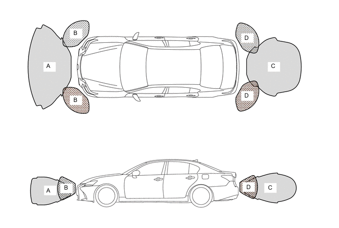
-
Multi-information Display
-
The items displayed on the multi-information display show the location of an obstacle, the approximate distance between the vehicle and the obstacle, and warning messages relating to a sensor malfunction, sensor freezing, or the presence of dirt on a sensor. When any warning messages are displayed, the master warning light illuminates and the multi buzzer in the combination meter assembly sounds.
-
The number of lines shown on the display changes based on the actual distance, and the lines flash when the distance is short.
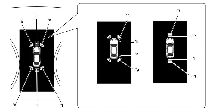
Text in Illustration *a Front Corner Sensor LH *b Front Center Sensor *c Front Corner Sensor RH *d Rear Corner Sensor LH *e Rear Center Sensor *f Rear Corner Sensor RH *g Long *h Short
-
-
Multi Display
-
The items displayed on the multi display show the location of an obstacle and the approximate distance between the vehicle and the obstacle, warning messages relating to sensor malfunction, sensor freezing, or presence of dirt on the sensor. When any warning messages are displayed, the master warning light illuminates and the multi buzzer in the combination meter assembly sounds.
-
The distance is shown by the number of lines and color based on the actual distance. The display usually illuminates in yellow. When the distance is short, it illuminates in red.
-
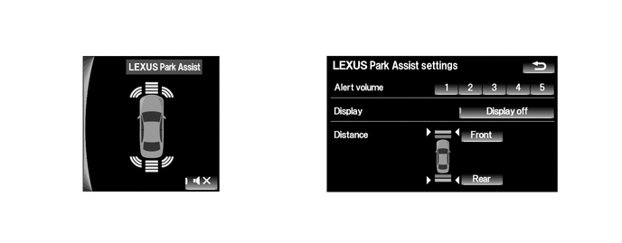
The display timing and detection distance on the multi display can be customized.
-
-
Clearance Warning Buzzer Mute Function
-
When a sensor detects an obstacle with the shift lever in a position other than P or R, the buzzer can be temporarily muted using the buzzer mute switch in the multi-display*1 or accessory meter assembly*2.
-
*1: Models with 8-inch display
-
*2: Models with 12.3-inch display
-
-
The mute function is canceled if the buzzer mute switch is pressed again or the vehicle speed reaches a certain level
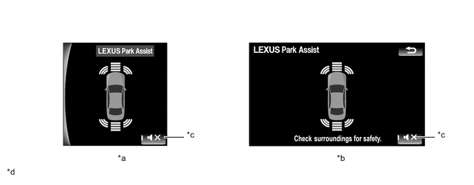
Text in Illustration *a Models with 12.3-inch Display *b Models with 8-inch Display *c Buzzer Mute Switch *d The illustrations shown are examples only. The illustrations may differ from the actual vehicle screens.
-
-
-
DIAGNOSIS
-
If the system cannot activate its detection function due to a malfunction in an ultrasonic sensor, it alerts the driver of the malfunction by the sounding the multi buzzer in the combination meter assembly. For details, refer to the Repair Manual.
-