TELEMATICS SYSTEM
-
FUNCTION OF MAIN COMPONENTS
-
G-BOOK
-
The main components in the G-BOOK have the following functions:
Component Function Telephone Switch Assembly When the telephone switch assembly is pressed, a switch signal is sent to the telematics transceiver (DCM). (When a manual maintenance check or manual emergency call is performed.) LED Indicator Light*1 Green
-
Turns on when the system is under a service contract and operating normally within the service area.
-
Blinks during a call or a maintenance check and turns off when the system is malfunctioning.
Red
-
Turns on when the vehicle is not within the service area.
-
Blinks when a call is made while the system is still malfunctioning.
-
Blinks when in diagnostic mode to indicate a DTC.
Telephone Microphone Assembly
-
When the hands-free function is used: sends the microphone voice signal to the multi-media module receiver assembly.
-
When an emergency call is made: sends the microphone voice signal to the telematics transceiver (DCM).
Telephone Antenna Assembly Sends and receives the data and voice signals used for the G-BOOK service through a communication network. Telematics Transceiver (DCM)*2 Uses the telephone antenna assembly to send and receive the data and voice signals used for the G-BOOK service through a communication network.
-
When the operator service is used: sends a received voice signal to the multi-media module receiver assembly.
-
When the operator service is used: sends a sent voice signal the multi-media module receiver assembly, and to the telephone antenna assembly.
-
When an emergency call is made: sends a received voice signal to the vehicle speakers.
-
When an emergency call is made: receives a sent voice signal from the telephone microphone assembly.
-
When an emergency call is made: sends a mute signal to the stereo component amplifier assembly. (Mute function becomes active during the call.)
-
When an emergency call is made: sends the location information to the G-BOOK center.
-
When a warning comes on, the telematics transceiver (DCM) receives a signal indicating the failure or malfunction of a system and sends the signal to the G-BOOK center.
-
When the theft deterrent system is activated, the telematics transceiver (DCM) sends a signal to the G-BOOK center indicating that the security horn has sounded.
Navigation Antenna Assembly
-
Receives GPS radio waves and sends them to the multi-media module receiver assembly.
-
Transmits the vehicle location together with the emergency call.
Main Body ECU (Multiplex Network Body ECU) Sends a security horn sounding signal to the multi-media module receiver assembly when the theft deterrent system is activated. Accessory Meter Assembly*3 The multi display receives an image signal from the multi-media module receiver assembly and displays the image on its screen. Multi-display*4 Multi-media Module Receiver Assembly
-
Sends and receives the data used for the G-BOOK service to and from the telematics transceiver (DCM) using a telematics data signal.
-
When the operator service is used: sends the 'sent voice signal' from the telephone microphone to the telematics transceiver (DCM).
-
When the operator service is used: sends the 'received voice signal' from the telematics transceiver (DCM) to the stereo component amplifier assembly using a MOST signal.
-
When the vehicle location information is periodically sent to the telematics transceiver (DCM).
Stereo Component Amplifier Assembly Receives the received voice signal sent from the multi-media module receiver assembly and outputs it as sound from the vehicle speakers. (When the hands-free function is used.) Remote Touch Sends operating signals to the multi-media module receiver assembly. Center Airbag Sensor Assembly Sends an activation signal to the telematics transceiver (DCM) when the airbags deploy. (An automatic emergency call is made.) Tech Tips
*1: The green and red indicator lights turn on for 5 seconds immediately after the power switch is turned on (ACC).
*2: Models with telematics transceiver (DCM)
*3: Models with 12.3-inch display
*4: Models with 8-inch display
-
-
-
ERA-GLONASS
-
The main components in the ERA-GLONASS have the following functions:
Component Function Map Light Assembly Telephone Microphone Assembly Receives the user's voice through the microphone module. Manual (SOS) Switch When pressed, allows the driver to connect to and communicate with the PSAP as an emergency assistance button (SOS) service. Manual (SOS) Switch Indicator Green
-
Turns on when the system is operating normally with in the service area.*
-
Blinks during a call and turns off when the system is malfunctioning.
Red
-
Illuminates to warn the user when a malfunction occurs in the system.
-
Turns off when the system is operating normally.
Telematics Transceiver (DCM)
-
Connects to the PSAP and allows the driver to speak with the call center operator when the automatic emergency call service or the manual emergency call service is active.
-
The cellular phone module makes or receives calls.
-
The telematics transceiver receives signals from the GNSS antenna, calculates the position of the vehicle and transmits it to the PSAP.
-
Controls the on/off and blinking actions of the manual (SOS) switch indicator.
-
Dims the manual (SOS) switch indicator when the taillight relay on signal is received.
-
Sends the PSAP operator's voice and voice prompts to the front No. 2 speaker assembly RH.
Mobilephone Battery
(Back-up Battery)
Is built into the telematics transceiver and supplies power to the telematics transceiver when the automatic emergency call service is activated and the vehicle battery cannot supply power. Telephone Antenna Assembly Telephone Antenna Is for a cellular phone antenna which is compatible with the transmission and reception of frequency bands of cellular phones. It transmits signals from the telematics transceiver and receives signals from the call center. GNSS Antenna Receives the signals from GNSS satellites and transmits these signals to the telematics transceiver. Telephone Microphone Assembly Receives the user's voice through the microphone module. Center Airbag Sensor Assembly Sends an activation signal to the telematics transceiver when the airbags deploy. (An automatic emergency call service is made.) Front No. 2 Speaker Assembly RH Outputs the PSAP operator's voice. Multi-media Module Receiver Assembly Receives microphone voice signals from the telematics transceiver (DCM). Stereo Component Amplifier Assembly Inputs the mute signal from the telematics transceiver (DCM) to mute any audio sound. Combination Meter Assembly Sends the vehicle speed signal to the telematics transceiver and multi-media module receiver assembly. *: ERA-GLONASS is available in Russia and Kazakhstan.
-
-
-
-
FUNCTION
-
G-BOOK
-
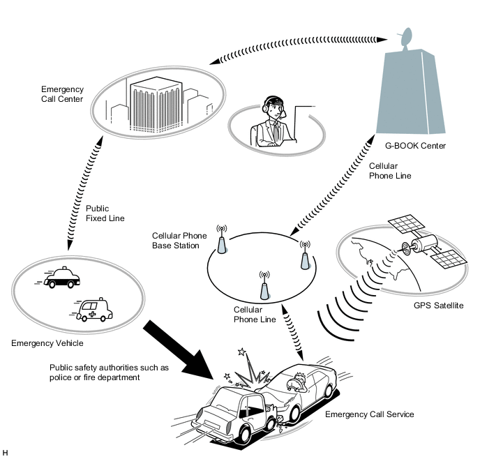
Emergency Call Service
-
The emergency call service automatically makes a call to a G-BOOK center operator in the event of an accident, such as one that makes airbags deploy, in order to support prompt attendance by emergency personnel.
-
In the event of trouble such as an accident or sudden illness, the telematics transceiver (DCM) can be used to call the emergency call center and send location information and the registered user information.
-
The emergency call service can be activated either manually or automatically to contact the G-BOOK center.
Call Method Operation Condition Automatic Call An automatic call is made in the event of an accident, such as one that makes the airbags deploy. The call occurs regardless of the condition of the occupants. Manual Call In the event of a sudden illness or an accident that does not cause the airbags to deploy, a manual call can be made by pressing the emergency call switch in the overhead console. (To press the emergency call switch, the emergency call switch cover needs to be removed.)
-
The emergency call service operation and contract conditions can be confirmed by accessing the G-BOOK center and performing the following maintenance checks.
Maintenance Check Outline Automatic Maintenance Check The telematics transceiver (DCM) automatically and periodically accesses the emergency call center to confirm if the user is still registered. Manual Maintenance Check The user can press the emergency call switch for 10 seconds or more while the green and red indicator lights are on immediately after the power switch is turned on (IG) to access the G-BOOK center and confirm that they are still registered. Tech Tips
In the following cases, the emergency call service may not be available or the service quality may suffer.
-
The G-BOOK online service has not been established or the first manual maintenance check has not been completed.
-
Communication is interrupted due to a malfunction of the telematics transceiver (DCM) or any other related device.
-
The location cannot be determined.
-
Communication is interrupted due to a service provider system malfunction.
-
Communication problems occur in the communication network used for the emergency call system.
-
The emergency call service is suspended or halted due to emergency call provider reasons.
-
Although a manual call is made, the situation cannot be confirmed because the user cannot respond to questions from the G-BOOK center.
-
-
-
Theft Tracking Service
-
The theft tracking service notifies the G-BOOK center that the alarm has operated when the theft deterrent system is activated.
-
The G-BOOK center makes a call to the user to notify them that the alarm has operated. If the call cannot get thorough, the G-BOOK center sends a short message service (SMS) message.
-
In the event of theft, the vehicle location can be tracked as requested by the user. If requested by the user, a G-BOOK operator asks the authorities to find the stolen vehicle and take the case under their control.
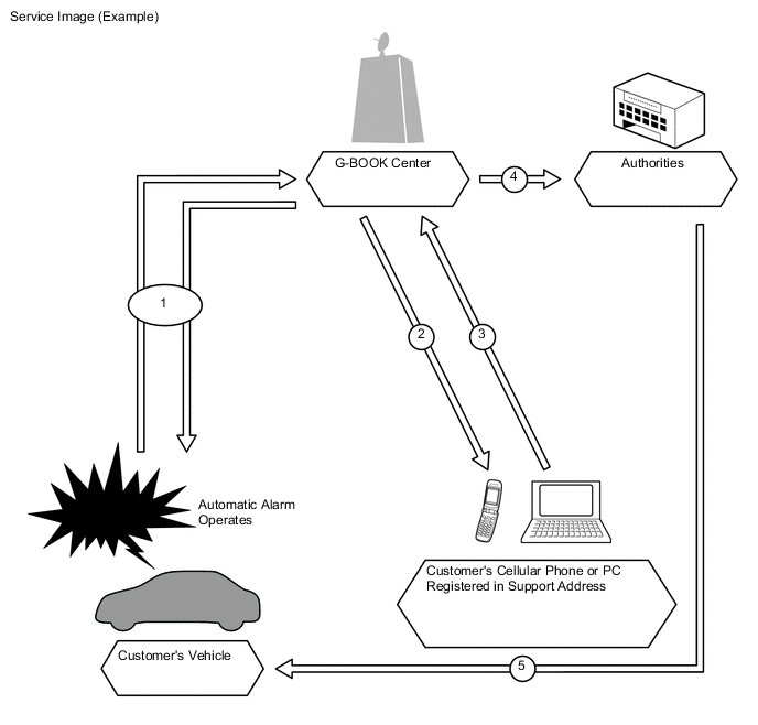
No. Process of Alarm Notification 1
-
Trouble occurs and the automatic alarm operates.
-
The vehicle location is confirmed.
2 The user is notified about the trouble by a call. If the call cannot get through, the user is notified by a short message service (SMS) message. 3 The user makes a request. 4 A call-out is made to the authorities. 5 The authorities respond to the scene. -
-
-
Remote Maintenance Service
-
Remote maintenance mail and warning notifications are provided as the remote maintenance service.
Contents Outline Remote Maintenance Mail
-
The telematics transceiver (DCM) sends information about the condition of the vehicle to G-BOOK center.
-
The G-BOOK center then notifies the vehicle user about the inspection timing and maintenance notice.
Warning Notification
-
The warning notification is a signal indicating a failure or malfunction of systems, information about which is received by the combination meter assembly.
-
This notification is sent by the telematics transceiver (DCM) to the G-BOOK center when the power switch is on (READY).
-
The G-BOOK center then notifies the vehicle user about the malfunction condition and how to cope with the problem based on the information received.
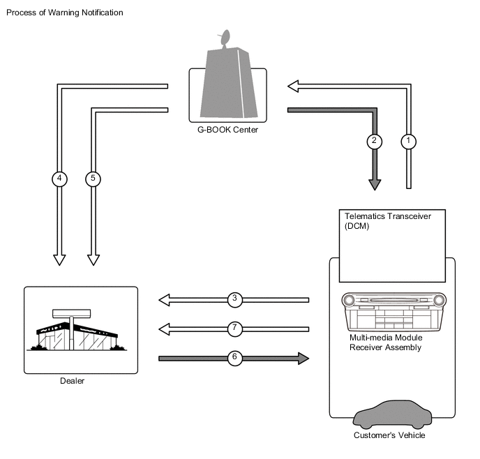
No. Process of Warning Notification 1 Information about the vehicle, details of any trouble or malfunctions, is sent. 2 The user is notified about the malfunction and how to cope with it. 3 The user requests a reservation. 4 Location and membership information. 5 Information about a failure or malfunction. 6 The reservation has been confirmed. 7 The user brings the vehicle in. -
-
Operator Service
-
The operator service allows the user to directly call a G-BOOK center operator. The user can ask the operator to set a destination or send a POI facility search result or news and weather forecasts information to the navigation system.
-
The operator service uses the multi-media module receiver assembly to make calls via the following devices.
-
Cellular phone connection type navigation system: Cellular phone. It is necessary to register the phone using the Bluetooth hands-free function.
-
Telematics transceiver connection type navigation system: Telematics transceiver (DCM). It is not necessary to register a phone using the Bluetooth handsfree function.
Function Outline Destination Setting Displays the specified destination location on the navigation system screen. Weather Forecast* Displays and reads out the vehicle location, destination or weather forecast for the specified area. News* Displays and reads out updates, society, sports and entertainment news. Tech Tips
*: Using the browser content display function built-in the navigation system, the following contents can be displayed. If news content is displayed, headlines are read out to assist the driver in checking the content easily even while driving.
-
-
Navigation System Link Function
-
The navigation system link function provides the navigation system with real-time information obtained from the G-BOOK center, offering more effective use of the navigation system for the user.
-
The navigation system link function has the following functions:
Function Outline G Route Search Searches for the most suitable route to the destination based on information about wide-area traffic congestion prediction. Searching for POIs on the WEB Transfers POI information, which was searched for on the Mapbar site, to the navigation system. A found POI can be set as a destination or registered as a G-memory point. G-memory Point
-
When a POI is searched for using the contents of G-BOOK.com or a website, it can be registered as a G-memory point of the memory points in the navigation system.
-
By registering POIs as a G-memory point, a list of G-memory points can be displayed without connecting to the G-BOOK center.
-
-
Other Function
-
The telematics system provides other functions in consideration of improving usability.
-
The other function is as follows:
Function Outline MY Request Content which is frequently searched for, such as news or weather forecast information, can be registered. After registration, information can be obtained through a simple operation. -
-
-
ERA-GLONASS
-
Automatic Emergency Call Service
-
If any of the airbags are deployed due to a serious collision, the telematics transceiver (DCM) receives the deployment signal from the center airbag sensor assembly. After receiving the deployment signal, the telematics transceiver (DCM) automatically makes an emergency call and transmits the vehicle location and user information to the PSAP closest to the vehicle.
-
The system is then automatically connected to a PSAP and the user can talk to a PSAP operator. The PSAP operator contacts the emergency services when the user is unable to answer.
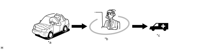
*a Airbag Deployment or Collision Detection *b Public Safety Answering Point (PSAP) *c Ambulance - -
-
-
Manual Emergency Call Service
-
By pushing the manual (SOS) switch during an on-road emergency, the telematics transceiver (DCM) transmits the vehicle location and user information, and calls to the PSAP closest to the vehicle.
-
The PSAP operator determines the level of the emergency based on the vehicle location and from the conversation with the user, and contacts the emergency services if necessary.

*1 Mayday Switch Assembly (Manual (SOS) Switch) - - *a Public Safety Answering Point (PSAP) - -
-
-
-
-
CONSTRUCTION
-
G-BOOK
-
Telephone Switch Assembly
-
The telephone switch assembly is available for the user to make a manual emergency call in the event of a medical emergency or an accident that does not cause the airbags to deploy.
-
The telephone switch assembly has an indicator light on the panel so that the user can confirm the operation of the system.
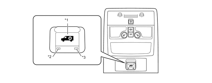
Text in Illustration *1 Telephone Switch Assembly *2 Indicator Light (Green) *3 Indicator Light (Red) - - Operation Condition of Indicator Light Indicator Light Operation Condition Green Red On Off The system is operating (the vehicle is within the cellular phone service area). Off On
-
The system is operating (the vehicle is outside the cellular phone service area).
-
A related device is malfunctioning (if the vehicle is within the cellular phone service area).
Blinks Off
-
During an emergency call.
-
During a manual maintenance check.
Off Blinks
-
An emergency call has failed.
-
An automatic maintenance check has failed (the vehicle is outside the cellular phone service area).
-
A manual maintenance check has failed.
-
A related device is malfunctioning.
On On
-
The power switch is turned on (ACC).
-
If the indicator lights remain on for 5 seconds or more, a related device is malfunctioning.
Off Off
-
The G-BOOK service contract was not renewed.
-
The power switch is off.
-
A related device is malfunctioning.
-
The first manual maintenance check has not been completed.
-
-
-
-
ERA-GLONASS
-
When the ignition switch is turned on, the manual (SOS) switch red indicator illuminates for 10 seconds and then turns off. Then, the manual (SOS) switch green indicator will illuminate for 2 seconds. Illuminates, blinks or turns off depending on the mode type.
-
When the ignition switch is turned off, the manual (SOS) switch red indicator and manual (SOS) switch green indicator turn off. However, if the ignition switch is turned off when an automatic emergency call is in progress, the call continues and the indicator lights continue operating.
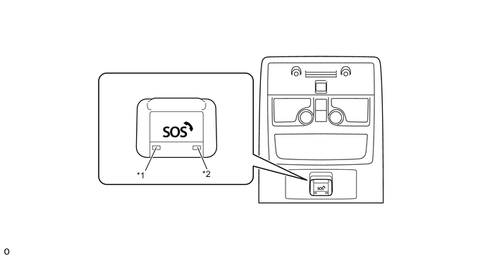
*1 Manual (SOS) Switch Green Indicator *2 Manual (SOS) Switch Red Indicator -
Indicators shown in each mode are as follows:
Indicator Light Operation Condition Green Red ON OFF The system is operating (the vehicle is within the cellular phone service area). OFF ON
-
A related device is malfunctioning.
-
The mobilephone battery (back-up battery) needs to be replaced.
Blinks OFF An emergency call is being performed. OFF Blinks An emergency call has failed. OFF OFF The ignition switch is off. -
-
-
-
DIAGNOSIS
-
G-BOOK
-
For details on the procedure required to enter the service menu screen, refer to the Repair Manual.
-
-
ERA-GLONASS
-
If there is a malfunction in the system, the telematics transceiver (DCM) stores Diagnostic Trouble Codes (DTCs) in its memory. For details, refer to the Repair Manual.
-
-