TELEMATICS SYSTEM
Figure 1. Models with G-BOOK 1
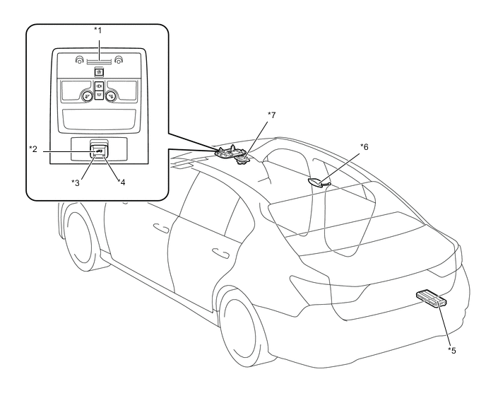
| *1 | Map Light Assembly - Telephone Microphone Assembly |
*2 | Telephone Switch Assembly |
| *3 | Indicator Light (Green) | *4 | Indicator Light (Red) |
| *5 | Stereo Component Amplifier Assembly | *6 | Telephone Antenna Assembly |
| *7 | Front No. 2 Speaker Assembly RH | - | - |
Figure 2. Models with G-BOOK 2
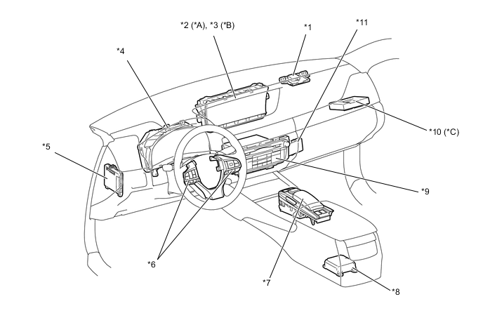
| *A | Models with 8-inch Display | *B | Models with 12.3-inch Display |
| *C | Models with Telematics Transceiver (DCM) | - | - |
| *1 | Navigation Antenna Assembly | *2 | Multi-display |
| *3 | Accessory Meter Assembly | *4 | Combination Meter Assembly |
| *5 | Main Body ECU (Multiplex Network Body ECU) | *6 | Steering Pad Switch Assembly |
| *7 | Remote Touch | *8 | Center Airbag Sensor Assembly |
| *9 | Multi-media Module Receiver Assembly | *10 | Telematics Transceiver (DCM) |
| *11 | Central Gateway ECU | - | - |
Figure 3. Models with ERA-GLONASS 1
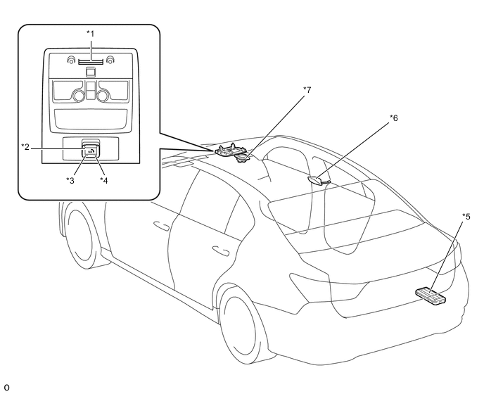
| *1 | Map Light Assembly - Telephone Microphone Assembly |
*2 | Manual (SOS) Switch |
| *3 | Indicator Light (Green) | *4 | Indicator Light (Red) |
| *5 | Stereo Component Amplifier Assembly | *6 | Telephone Antenna Assembly |
| *7 | Front No. 2 Speaker Assembly RH | - | - |
Figure 4. Models with ERA-GLONASS 2
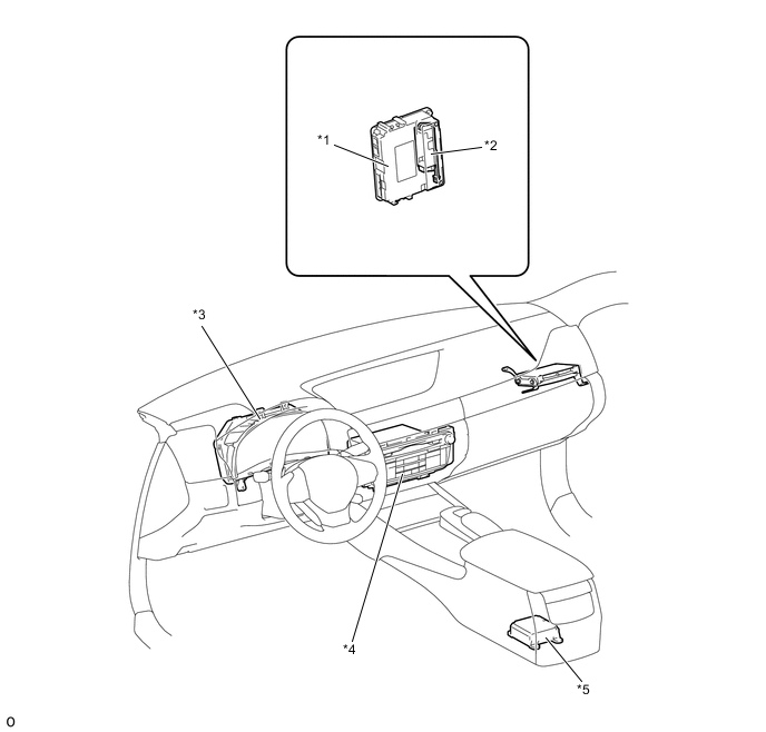
| *1 | Telematics Transceiver (DCM) | *2 | Mobilephone Battery (Back-up Battery) |
| *3 | Combination Meter Assembly | *4 | Multi-meia Module Receiver Assembly |
| *5 | Center Airbag Sensor Assembly | - | - |