BLIND SPOT MONITOR SYSTEM
-
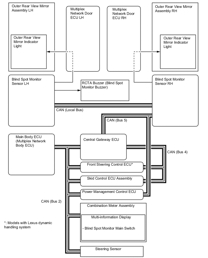
FUNCTION OF MAIN COMPONENTS
Component Function Blind Spot Monitor Sensors LH and RH
-
Radiate radar waves from the blind spot monitor sensor to the blind spot sensor detection area, use the reflected millimeter waves for detecting the presence of a vehicle, the vehicle-to-vehicle distance and the relative speed, and then transmit this information to the built-in signal processing circuit.
-
The signal processing circuit determines if a vehicle is present, and illuminates or blinks the outer rear view mirror indicator light accordingly.
Outer Rear View Mirror Assemblies LH and RH Outer Rear View Mirror Indicator Light
-
Illuminates to inform the driver that a vehicle has been detected in the blind spot detection area (blind spot monitor function).
-
Flashes to inform the driver when the turn signal lever is operated if a vehicle has been detected in the blind spot detection area (blind spot monitor function).
-
Flashes when another vehicle is detected in the alert area while the vehicle is backing up (RCTA function).
Headlight Dimmer Switch Assembly Transmits the turn switch signal to the blind spot monitor sensors LH and RH. Combination Meter Assembly Multi-information Display
- Blind Spot Monitor Main Switch
-
Operating blind spot monitor main switch allows the operation of the blind spot monitor system to be enabled or disabled.
-
When a malfunction is detected in the blind spot monitor sensors or the blind spot monitor sensors determine that control is not possible, a message is displayed on the multi-information display to warn the driver.
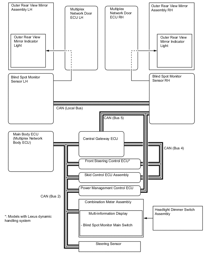
Steering Sensor Transmits the steering angle signal to the blind spot monitor sensors LH and RH. Skid Control ECU Assembly Transmits the vehicle speed signal to the blind spot monitor sensors LH and RH. Main Body ECU (Multiplex Network Body ECU) Transmits the destination signal to the blind spot monitor sensors LH and RH. Central Gateway ECU Gateway function of CAN communication. Power Management Control ECU Transmits the reverse signal to the blind spot monitor sensors LH and RH. RCTA Buzzer (Blind Spot Monitor Buzzer)*1 Sounds when a vehicle is detected in the alert area while backing up. Front Steering Control ECU*2 Transmits the VGRS signal to the blind spot monitor sensors LH and RH.
-
*1: Models with RCTA function
-
*2: Models with Lexus dynamic handling system
-
-
OPERATING CONDITION
-
Blind Spot Monitor Function
-
The blind spot monitor function operates when both of the following conditions are met:
-
The blind spot monitor main switch is on.
-
The vehicle speed is greater than approximately 16 km/h (10 mph).
-
-
The blind spot monitor function can detect vehicles in its detection areas.
-
The detection areas formed by the blind spot monitor sensors LH and RH are as shown below:
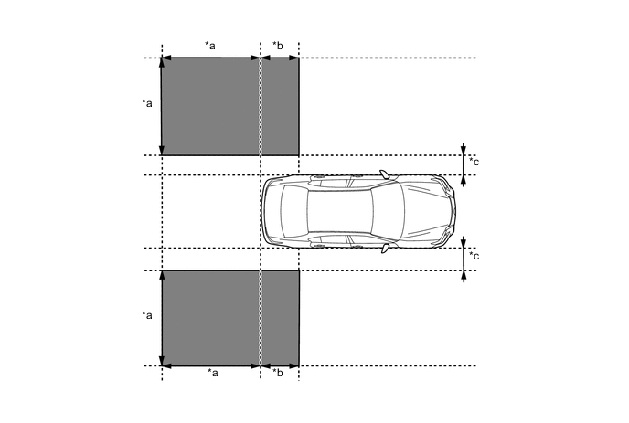
Text in Illustration *a 3.0 m (9.8 ft.) *b 1.0 m (3.3 ft.) *c 0.5 m (1.6 ft.) - - 
Blind Spot Detection Area - -
-
-
The following are examples of the operation of the function:
-
The driver's vehicle is overtaken by another vehicle in the adjacent lane.
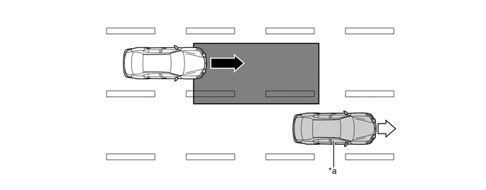
Text in Illustration *a Driver's Vehicle - - 
Vehicle Speed (Fast) 
Vehicle Speed (Slow) Blind Spot Detection Area - - -
When another vehicle enters the detection area of the driver's vehicle due to a lane change.
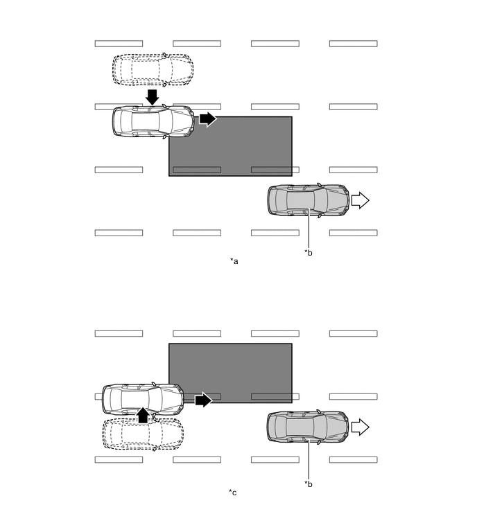
Text in Illustration *a Another vehicle enters the detection area during lane change (merge in) (Type 1). *b Driver's Vehicle *c Another vehicle enters the detection area during lane change (merge in) (Type 2). - - Motion Direction of Another Vehicle Motion Direction of Driver's Vehicle Detection Area - -
-
-
-
The RCTA function can detect vehicles in its detection areas.
-
The system continuously measures the relative speed of an approaching vehicle and its distance. If it is determined that the approaching vehicle will cross in the path of driver's vehicle, the Estimated Crossing Time (ECT) is calculated. When the ECT is 2.5 seconds or less, the system alerts the driver by flashing the outer rear view mirror indicator lights and sounding the RCTA buzzer.
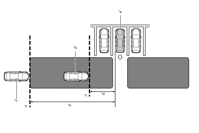
Text in Illustration *a Driver's Vehicle *b Target Vehicle (Approximately 8 km/h (5 mph)) *c Target Vehicle (Approximately 28 km/h (18 mph)) *d Approximately 5.5 m (18.0 ft.) *e Approximately 20 m (66 ft.) *f Target Detection Line Alert Area - - -
Normal Parking
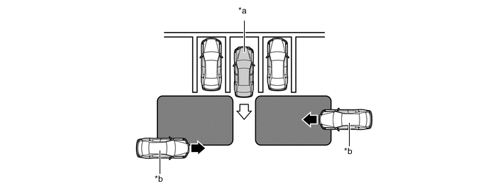
Text in Illustration *a Driver's Vehicle *b Target Vehicle Alert Area - - -
Angle Parking
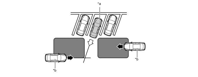
Text in Illustration *a Driver's Vehicle *b Target Vehicle Alert Area - -
-
-
-
CONSTRUCTION
-
Blind Spot Monitor Sensor
-
The blind spot monitor sensor consists of a millimeter wave radar circuit and a signal processing circuit.
-
The millimeter wave radar uses frequencies in the 24 GHz band.
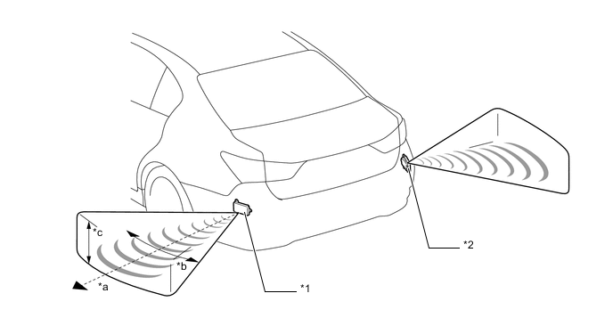
Text in Illustration *1 Blind Spot Monitor Sensor LH *2 Blind Spot Monitor Sensor RH *a Distance: Approximately 50 m (164 ft.) *b Horizontal Angle: Approximately 150° *c Vertical Angle: Approximately 20° - - -
The distance to the object, azimuth and relative speed are calculated from the information that is provided by the reflected millimeter wave radar as described below:
Item Calculation Method Distance Calculated from the length of time that has elapsed from the time the waves of the millimeter wave radar have been emitted, until the reflected waves are received by the millimeter wave radar circuit. The distance is approximately 50 m (164 ft.). Azimuth Calculated from the reception angle of the millimeter wave radar reflections received. The detection angle has a horizontal range of approximately 150° and a vertical range of approximately 20°. Relative Speed Calculated by utilizing the change (Doppler effect*) that occurs in the frequency of the reflected millimeter wave radar waves. Tech Tips
*: The Doppler effect causes the observer to perceive the radio waves emitted by a moving object to be a higher frequency as it approaches, and to be a lower frequency as it recedes. This phenomenon is created because when an object is located far away, the radio waves are perceived at higher frequencies than those of the radio source. An SST is used if radar axis confirmation is needed. For details, refer to the Repair Manual.
-
-
-
OPERATION
-
Blind Spot Monitor Function
-
According to operation conditions, the blind spot monitor function promotes safety confirmation by using the outer rear view mirror indicator light to inform the driver that another vehicle has entered the blind spot monitor sensor detection area of this vehicle.
-
The outer rear view mirror indicator light informs the driver that a vehicle is present in the blind spot detection area by illuminating when the turn light switch is not operated, and by flashing when a vehicle is present and the turn light switch is operated.
-
-
RCTA Function (Models with RCTA Function)
-
According to operation conditions, the RCTA function promotes safety confirmation by using the outer rear view mirror indicator lights and RCTA buzzer to inform the driver that another vehicle has entered the blind spot monitor sensor alert area of this vehicle.
-
When this vehicle is reversing, if a vehicle enters the alert area of the blind sport monitor sensors and it is determined the vehicle will cross in the path of this vehicle, the system alerts the driver by flashing the outer rear view mirror indicator lights and sounding the RCTA buzzer.
-
-
-
DIAGNOSIS
-
The blind spot monitor system is equipped with a diagnosis function that can display warning messages in the multi-information display. For details, refer to the Repair Manual.
-