VARIABLE GEAR RATIO STEERING SYSTEM
-
FUNCTION OF MAIN COMPONENTS
Component Function Steering Actuator Assembly Motor Rotates to create the operating angle of the steering actuator assembly upon receiving the signals from the front steering control ECU. Reduction Mechanism Uses a strain wave gear type reduction mechanism to reduce the rotation of the motor to the 1:51 ratio. Lock Solenoid Locks the motor shaft so that the motor will not rotate in case of a system malfunction. Rotation Angle Sensor Outputs the rotational angle of the motor to the front steering control ECU. Combination Meter Assembly Multi-information Display Displays the warning message to inform the driver of a malfunction in the system. Master Warning Light Illuminates when the warning message is displayed in the multi-information display. Multi Buzzer Sounds to warn the driver of a malfunction in the system. Steering Sensor Detects the steering direction and angle of the steering wheel. Front Steering Control ECU
-
Calculates the target vehicle characteristics based on the signals from the steering sensor, vehicle speed and each ECU.
-
Drives the motor of the steering actuator assembly.
-
Sends the control signal to the rear steering control ECU.
Rear Steering Control ECU Drives the motor of the rear steering link assembly in accordance with a rear wheel turning angle signal from the front steering control ECU. Power Steering ECU Assembly Sends the steering assist signal to the steering control ECU. Skid Control ECU Assembly
-
Outputs the vehicle speed signal.
-
Requests the steering control (EPS system and LDH system) during cooperative control.
Absorber Control ECU Outputs the damping force control condition. Driving Support ECU Assembly (Models with Pre-crash Safety System) Requests the steering control (EPS system and LDH system) during cooperative control. ECM Sends information about the drive mode selected by the drive mode select to each ECU. -
-
CONSTRUCTION
-
Steering Actuator Assembly
-
The steering actuator assembly consists of a housing, a motor, a reduction mechanism, an output shaft, and a lock mechanism.

Text in Illustration *1 Output Shaft *2 Reduction Mechanism *3 Motor *4 Lock Mechanism *5 Spiral Cable - - 
From Steering Wheel 
To Power Steering Link Assembly
-
-
Motor
-
A compact, high power output, and low noise brushless type motor is used. This motor is enclosed in the housing.
-
This motor mainly consists of a magnet, a coil, and a motor shaft. The motor shaft is coupled to the wave generator of the reduction mechanism in order to transmit the rotational movement of the motor to the reduction mechanism.
-
This motor, which is controlled by the signal from the front steering control ECU, rotates either clockwise or counterclockwise, depending on the direction in which the steering wheel is turned.
-
The rotation angle sensor detects the rotational direction and rotational angle of the motor.
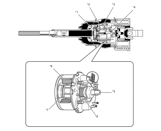
Text in Illustration *1 Reduction Mechanism *2 Housing *3 Motor *4 Lock Mechanism *5 Motor Shaft *6 Coil *7 Magnet *8 Rotation Angle Sensor
-
-
Reduction Mechanism
-
The reduction mechanism uses strain wave gearing, which is compact and highly accurate, and creates a large reduction gear ratio (1:50) using a small number of components.
-
This reduction mechanism consists of a driven gear, a stator gear, a flexible gear, and a wave generator.
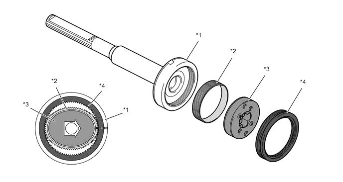
Text in Illustration *1 Driven Gear *2 Flexible Gear *3 Wave Generator *4 Stator Gear Construction of Reduction Mechanism Item Construction Stator Gear (Input)
-
Has a rigid body and a ring shape, and contains 102 teeth along the inner circumference.
-
Positioned parallel to the driven gear.
-
Coupled to the housing of the steering actuator assembly.
Driven Gear (Output)
-
Has a rigid body and a ring shape, and contains 100 teeth along the inner circumference.
-
Positioned parallel to the stator gear.
-
Coupled to the output shaft of the steering actuator assembly.
Flexible Gear
-
Has a flexible metal body that forms a belt shape and contains 100 teeth along the outer circumference.
-
Located outside of the wave generator, and positioned in such a way that its gear teeth are meshed with the inside of both the stator gear and the driven gear.
Wave Generator
-
Consists of an oval-shaped cam and a ball bearing that is fitted around the cam.
-
Coupled to the motor shaft of the motor and rotates inside the flexible gear while pushing the flexible gear against the stator gear and the driven gear.
-
-
-
Lock Mechanism
-
This system contains a lock mechanism that mechanically locks the motor so that the motor will not rotate if a malfunction occurs. Along with this, the housing and the output shaft are integrated.
-
The lock mechanism is mounted on the motor. The mechanism consists primarily of a lock holder that is secured to the motor shaft, a lock lever that is mounted on the housing, and a lock solenoid that operates the lock lever.
-
When the lock mechanism is activated, the front steering control ECU turns off the current to the lock solenoid, and the return spring pushes the lock lever against the lock holder. Then, the lock lever meshes with the groove in the lock holder in order to mechanically lock the movement of the motor. When the lock is disengaged, the front steering control ECU turns on the current to the lock solenoid, thus disengaging the lock lever and the lock holder and freeing the movement of the motor.
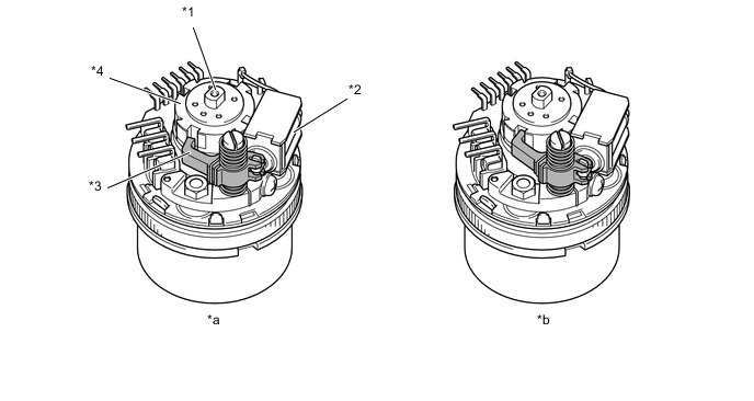
Text in Illustration *1 Motor Shaft *2 Lock Solenoid *3 Lock lever *4 Lock Holder *a Unlock State (Lock Solenoid On) *b Lock State (Lock Solenoid Off)
-
-
-
OPERATION
-
Reduction Mechanism Operation
-
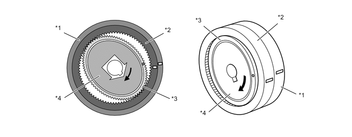
The flexible gear is fitted inside the driven gear and stator gear as illustrated. Furthermore, the wave generator is fitted inside the flexible gear. The rotational movement of the wave generator causes the flexible gear to become deformed into an oval shape. The teeth at the major axis of the oval shape mesh with the teeth of the driven gear and stator gear, and the teeth at the minor axis are disengaged.
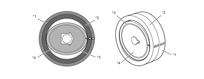
Text in Illustration *1 Driven Gear *2 Stator Gear *3 Flexible Gear *4 Wave Generator -
When the stator gear is fixed and the wave generator rotates clockwise, the flexible gear undergoes an elastic deformation. This causes the meshed areas between the flexible gear, driven gear and stator gear to move consecutively.
Text in Illustration *1 Driven Gear *2 Stator Gear *3 Flexible Gear *4 Wave Generator -
When the wave generator makes 1 rotation, the flexible gear moves counterclockwise by 2 teeth because it has 2 fewer teeth than the stator gear. The driven gear and the flexible gear have the same number of teeth, so their rotational movements are identical. Therefore, the driven gear (output) moves by 2 teeth.
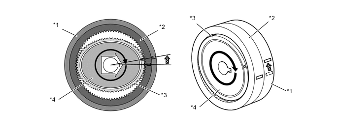
Text in Illustration *1 Driven Gear *2 Stator Gear *3 Flexible Gear *4 Wave Generator 
Stator Gear Move Clockwise by 2 Teeth - -
-
-
-
FAIL-SAFE
-
a system malfunction occurs, it turns off the lock solenoid of the lock mechanism and locks the motor in the steering actuator assembly.
-
-
DIAGNOSIS
-
If the front steering control ECU detects a malfunction in the VGRS system, the front steering control ECU lights up the master warning light, indicates the warning message on the multi-information display, sounds the multi buzzer to alert the driver of the malfunction.
-
The front steering control ECU will also store a Diagnostic Trouble Code (DTC). The DTC can be accessed through the use of a Global TechStream (GTS). For details, refer to the Repair Manual.
-