LEXUS DYNAMIC HANDLING SYSTEM
-
FUNCTION OF MAIN COMPONENTS
Component Function Steering Actuator Assembly Motor Rotates to create the operating angle of the steering actuator assembly upon receiving the signals from the front steering control ECU. Reduction Mechanism Uses a strain wave gear type reduction mechanism to reduce the rotation of the motor to the 1:51 ratio. Lock Solenoid Locks the motor shaft so that the motor will not rotate in case of a system malfunction. Rotation Angle Sensor Outputs the rotational angle of the motor to the front steering control ECU. Rear Steering Link Assembly Motor Rotates to create the turning angle of the rear wheel upon receiving the signals from the rear steering control ECU. Reduction Mechanism Uses a planetary gear type reduction mechanism to reduce the rotation of the motor. Stroke Sensor Detects the stroke amount of the rear steering link assembly. Rotation Angle Sensor Transmits the rotation angle of the motor to the rear steering control ECU. Combination Meter Assembly Multi-information Display Displays the warning message to inform the driver of a malfunction in the system. Master Warning Light Illuminates when the warning message is displayed in the multi-information display. Multi Buzzer Sounds to warn the driver of a malfunction in the system. Steering Sensor Detects the steering direction and angle of the steering wheel. Yawrate Sensor
-
Detects the vehicle's longitudinal and lateral acceleration.
-
Detects the vehicle's yaw rate.
Front Steering Control ECU
-
Calculates the target vehicle characteristics based on the signals from the steering sensor, vehicle speed and each ECU.
-
Drives the motor of the steering actuator assembly.
-
Sends the control signal to the rear steering control ECU.
Rear Steering Control ECU Drives the motor of the rear steering link assembly in accordance with a rear wheel turning angle signal from the front steering control ECU. Power Steering ECU Assembly Sends the steering assist signal to the front steering control ECU. Skid Control ECU Assembly
-
Outputs the vehicle speed signal.
-
Requests the steering control (EPS system and LDH system) during cooperative control.
Absorber Control ECU Outputs the damping force control condition. Driving Support ECU Assembly* Requests the steering control (EPS system and LDH system) during cooperative control. ECM Sends information about the drive mode selected by the drive mode select to each ECU.
-
*: Models with pre-crash safety system
-
-
SYSTEM CONTROL
-
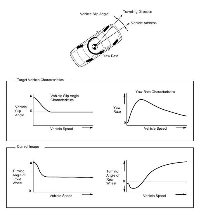
In the LDH system, target vehicle characteristics are provided in accordance with the vehicle speed to allow the turning angles of the front and rear wheels to be changed arbitrarily in response to the steered angle of the steering wheel.
-
The LDH system controls the turning angles of the front and rear wheels in accordance with the steered angle of the steering wheel and vehicle speed, thus achieving target vehicle characteristics.
-
Control in Normal Mode
-
In low speed range, yaw rate characteristics are set high to achieve reduction of the driver's steering effort. In addition, both to reduce discomfort caused by high yaw rate characteristics and to shorten the turning radius, vehicle slip characteristics in low speed range have been optimized. Through these types of target vehicle characteristics, steering feel is ensured, and reduction of the driver's steering effort and vehicle turning radius is achieved.
-
In medium speed range, yaw rate characteristics are set high, to ensure superior turning performance and a steering feel appropriate to the driver's intention.
-
In high speed range, the vehicle slip angle characteristics of the target vehicle characteristics are set to 0. In addition, the vehicle slip angle changing characteristics are set high, thus achieving both a high level of security and vehicle motion performance appropriate to the driver's intention.
-
-
Control in SPORT Mode
-
When SPORT S+ mode is selected by operating the drive mode select, the front steering control ECU changes the target vehicle characteristics to vehicle characteristics which are appropriate for sporty driving.
-
Compared to ECO, NORMAL and SPORT S modes, the vehicle response to steering operations is improved, thus offering driving pleasure during sporty driving.
-
-
Steering Cooperative Control
-
Brake Force Control on Roads with High and Low Friction Coefficient
-
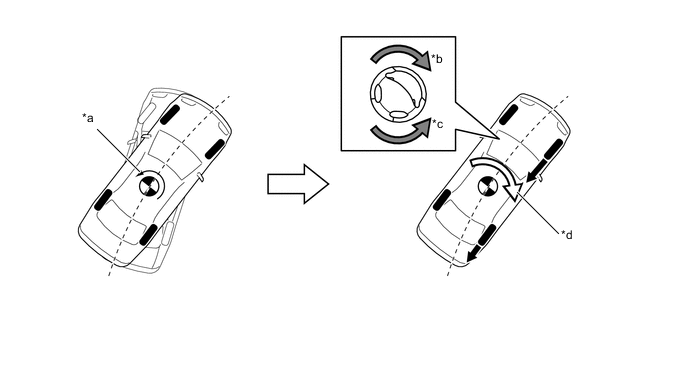
Brake force increases in the high μ (friction coefficient) area of the road and the vehicle attempts to deviate rightward (in the high μ side). Therefore, the front wheels are steered to face the vehicle leftward, thus counteracting the moment generated in the rotating direction. The rear wheels and front wheels are steered in opposite directions, thus controlling the lateral movement of the vehicle.
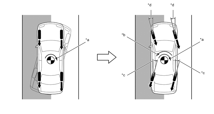
Text in Illustration (Illustration Provides Conceptual Image) *a Moment Generated due to Left and Right Brake Force Differences *b Control Moment by Steering Control *c Controls Turning Angle of Rear Wheels *d Controls Turning Angle of Front Wheels 
Brake Force - - 
Slippery Surface - -
-
-
Acceleration Control on Roads with High and Low Friction Coefficient
-
Drive force increases in the high μ (friction coefficient) area of the road and the vehicle tilts leftward (in the low μ side). Therefore, the front wheels are steered to face the vehicle rightward, thus counteracting the moment generated in the rotating direction. The rear wheels and front wheels are steered in opposite directions, thus controlling the lateral movement of the vehicle.
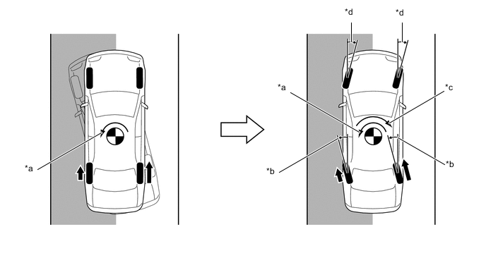
Text in Illustration (Illustration Provides Conceptual Image) *a Moment Generated due to Left and Right Drive Force Differences *b Controls Turning Angle of Rear Wheels *c Control Moment by Steering Control *d Controls Turning Angle of Front Wheels Motive Force - - Slippery Surface - - Tech Tips
-
On models without LDH system, VDIM controls the vehicle to maintain a straight driving line.
-
On models with LDH system, high brake force and drive force can be maintained during control due to increased vehicle stability.
-
-
-
Oversteering Control
-
When the rear wheels are slipping laterally, both normal brake control and drive force control and steering control of the front and rear wheels stabilize the vehicle movement. Stabilization moment is generated not only by brake force and drive force but also by steering control, thus stabilizing the vehicle without causing an extra speed reduction feel.
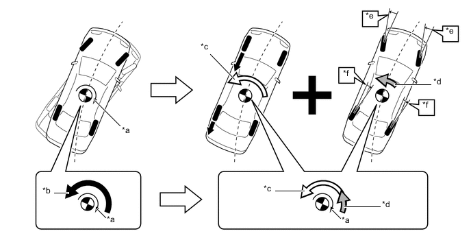
Text in Illustration (Illustration Provides Conceptual Image) *a Rear Wheel Skid Moment *b Moment Necessary to Suppress Oversteering *c Control Moment by Brake Control and Drive Force Control *d Control Moment by Steering Control *e Front Wheel Turning Angle Control *f Rear Wheel Turning Angle Control
-
-
Understeering Control
-
Brake force and drive force are controlled to generate force in the same direction as the turning direction, thus suppressing excessive lateral slippage. In addition, VGRS steering gear ratio is changed to suppress oversteer in the front wheels. Torque assist is applied in the return direction of the steering wheel, thus prompting the driver's steering operation.
Text in Illustration (Illustration Provides Conceptual Image) *a Front Wheel Skid Moment *b Steering Torque Assist Direction to Inform of Front Wheel Skid *c Steering Torque Assist Direction to Prevent Excessive Turning *d Control Moment by Brake Control and Drive Force Control
-
-
-
Pre-crash Safety System Cooperative Control
-
When the pre-crash safety system has judged a high possibility of collision, the LDH system changes the target vehicle characteristics to vehicle characteristics which prioritize collision prevention performance.
-
-
-
FAIL-SAFE
-
If a system malfunction occurs, it turns off the lock solenoid of the lock mechanism and locks the motor in the steering actuator assembly.
-
If a malfunction occurs in the DRS system, the rear steering control ECU gradually reduces or blocks current output to the motor to ban control of the turning angle of the rear wheels.
-
-
DIAGNOSIS
-
If the front steering control ECU detects a malfunction in the VGRS system, it lights up the master warning light, indicates the warning message on the multi-information display, sounds the multi buzzer to alert the driver of the malfunction.
-
If the rear steering control ECU detects a malfunction in the DRS system, it lights up the master warning light, indicates the warning message on the multi-information display, sounds the multi buzzer to alert the driver of the malfunction.
-
The front steering control ECU and rear steering control ECU will also store a Diagnostic Trouble Code (DTC). The DTC can be accessed through the use of a Global TechStream (GTS). For details, refer to the Repair Manual.
-