DYNAMIC RADAR CRUISE CONTROL SYSTEM
-
FUNCTION OF MAIN COMPONENTS
-
The main components in the dynamic radar cruise control system have the following functions:
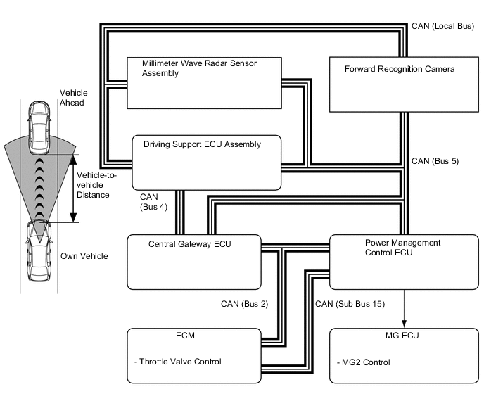
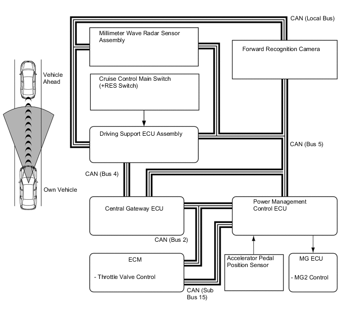
Component Function Millimeter Wave Radar Sensor Assembly Radiates millimeter radar waves forward, uses the reflected waves to detect the presence of a vehicle being driven ahead, the vehicle-to-vehicle distance and the relative speed, and then transmits this information to the driving support ECU assembly. Forward Recognition Camera
-
Detects lane markers and objects on the road ahead using the image captured by the monocular camera and sends the information to the driving support ECU assembly.
-
Transmits an operation signal to the camera heater.*1
Camera Heater (Forward Recognition Hood with Heater Sub-assembly)*1 The camera heater is heated according to signals from the forward recognition camera. Cruise Control Main Switch ON-OFF Button
-
Turns the cruise control system on and off.
-
Vehicle-to-vehicle distance control mode becomes be activated immediately after the main switch is turned on. The mode shifts to constant speed control mode by pressing and holding the button more than 1.5 sec.
+RES Switch The acceleration function and resumption of a preset speed can be performed by operating this switch. A signal is output to the driving support ECU assembly when this switch is operated. -SET Switch The deceleration function and vehicle speed setting resume signals are output to the driving support ECU assembly due to operation of this switch. CANCEL Switch A cancel signal can be output to the driving support ECU assembly through the operation of this switch. Vehicle-to-vehicle Distance Control Switch While the system is in the vehicle-to-vehicle distance control mode, the driver can operate the vehicle-to-vehicle distance control switch to select the vehicle-to-vehicle distance in 3 stages: long, middle and short. Driving Support ECU Assembly
-
Calculates the acceleration or deceleration required to achieve the target vehicle speed/target vehicle-to-vehicle distance based on signals from millimeter wave radar sensor assembly and forward recognition camera.
-
Transmits motive force request signal to the power management control ECU.
-
Transmits control status display request signals, warning display request signals and diagnosis signals for the dynamic radar cruise control system.
Power Management Control ECU
-
Increases and decreases the motive force in accordance with the acceleration or deceleration request signals transmitted by the driving support ECU assembly.
-
Transmits deceleration request signal to skid control ECU assembly.
Inverter with Converter Assembly
- Motor Generator ECU
Controls the motive force of MG2 in accordance with the signals from the power management control ECU. ECM Actuates the throttle control motor in accordance with the signals from the power management control ECU. Skid Control ECU Assembly
-
While the system is operating in vehicle-to-vehicle distance control mode, the skid control ECU assembly performs brake control in accordance with request signals from the power management control ECU.
-
Transmits signals such as wheel speed and estimated vehicle acceleration to the driving support ECU assembly.
-
Keeps the vehicle stopped through the brake hold function upon receiving a stop retention signal from the driving support ECU assembly.*2
Combination Meter Assembly Multi Buzzer When the driving support ECU assembly detects automatic cancel or warning signals while the vehicle is operating under cruise control system, this buzzer sounds to inform the driver. Master Warning Light Illuminates when there is a malfunction in the system. Multi-information Display During dynamic radar cruise control system operation, the multi-information display receives signals from the driving support ECU assembly in order to display the system conditions. Cruise Control Indicator Light
-
Comes on when constant speed control mode is entered.
-
Turns off if a malfunction occurs during constant speed control mode control.
Radar Cruise Control Indicator Light
-
Comes on when the cruise control main switch ON-OFF button is pressed to start the cruise control system.
-
Turns off if a malfunction occurs during vehicle-to-vehicle distance control mode control.
Cruise Control SET Indicator Light Illuminates when the vehicle speed is set during cruise control driving. Combination Meter Mirror ECU*3 During vehicle approach warning operation, the head up display receives signals from the combination meter assembly in order to display the approach warning and set speed. Throttle Body with Motor Assembly Throttle Control Motor Adjusts the throttle valve opening angle in accordance with signals from the ECM. Throttle Position Sensor Detects the throttle valve opening angle and outputs it to the ECM. Brake Actuator Assembly Actuates the brakes in accordance with the signals from the skid control ECU assembly. Stop Light Control Relay (No. 1 Integration Relay) Illuminates the stop light in accordance with the stop light illumination request signal from the skid control ECU assembly. Skid Control Buzzer Assembly Sounds on receiving a signal from the driving support ECU assembly and alerts the driver that the distance between the vehicles is short. Speed Sensors Detects the wheel speed of each of the 4 wheels and outputs it to the skid control ECU. Accelerator Pedal Sensor Assembly Detects the accelerator pedal depression degree and outputs it to the power management control ECU. Shift Lever Position Sensor Detects the shift position and transmits signals to the power management control ECU. Steering Sensor Detects the angle and direction of steering and transmits signals to the driving support ECU assembly. Yawrate Sensor Detects the yaw rate of the vehicle and transmits signals to the driving support ECU assembly. Stop Light Switch Assembly Detects the pressing of the brake pedal and transmits its signal to the driving support ECU assembly and skid control ECU assembly. Parking Brake ECU Assembly*2 When the system is canceled during stop retention control, operates the parking brake actuator assembly. Parking Brake Switch*2 Outputs a parking brake application signal to the parking brake ECU assembly. VSC OFF Switch Enables the driver to select normal mode, TRC OFF mode or VSC OFF mode. Parking Brake Actuator Assembly*2 Operates the parking brake receiving a signal from the parking brake ECU assembly. Transmission Shift Switch Assembly While the vehicle is being driven in D mode or M mode, this switch outputs a signal to the power management control ECU when the switch is pulled to "+" or "-". Transmission Floor Shift Assembly Transmission Control Switch While the vehicle is being driven in M mode, this switch outputs a signal to the power management control ECU when the shift lever is moved toward "+" or "-". Central Gateway ECU Transmits the signal between the CAN communication bus. *1: Models with camera heater
*2: Models with full-speed following function
*3: Models with headup display
-
-
-
FUNCTION
-
Control of Dynamic Radar Cruise Control System Varies Depending on Mode
-
A: Constant speed control mode
-
B: Vehicle-to-vehicle distance control mode
-
C: Vehicle-to-vehicle distance control mode (models with full-speed following function)
Function Outline Mode A B C Constant Speed Control Controls the motive force through the power management control ECU in order to adjust the vehicle speed to the set vehicle speed. ○ ○ ○ Deceleration Control Performs engine, MG2 and brake control in order to decelerate the vehicle so that the vehicle-to-vehicle distance between the driver's own vehicle and the vehicle ahead equals the set speed. - ○ ○ Follow-up Control After effecting deceleration control, the vehicle follows the vehicle ahead in order to maintain the proper vehicle-to-vehicle distance in accordance with the vehicle speed. - ○ ○ Acceleration Control Accelerates the vehicle in order to attain the set vehicle speed when the vehicle or the vehicle ahead has changed lanes. - ○ ○ Stop Control Detects if the vehicle ahead has stopped, performs motive force control and stops the vehicle while maintaining proper vehicle-to-vehicle distance. - - ○ Stop Retention Control Judges if the vehicle is stopped, performs brake control and keeps the vehicle stopped through the brake hold function. - - ○ Start Control Detects that the vehicle ahead starts moving again, displays the message on the multi-information display to urge the driver to perform the start-off operation (to operate the cruise control main switch or depress the accelerator pedal), and resumes follow-up control after the vehicle is started. - - ○ Set Control While this system fulfils the following condition and the cruise control main switch is pressed to the -SET direction and released when the ON-OFF button on the cruise control main switch has been pressed to turn the system on, the driving support ECU assembly stores the vehicle speed and maintains the vehicle constantly at that speed. ○ ○ ○ The vehicle is running within the following speed range:
-
Approx. 50 km/h to 200 km/h (30 mph to 125 mph)
○ - - The vehicle is running within the following speed range:
-
Approx. 50 km/h to 180 km/h (30 mph to 112 mph)
When there is a preceding vehicle, the set speed is kept at approx. 50 km/h [30 mph] even if the vehicle is being driven below that speed.
- ○ ○ Low Speed Limit Control The low speed limit is the lowest speed that the dynamic radar cruise control system can be set at and the speed limit is designed to be approx. 40 km/h (25 mph). The cruise control system cannot be set below this speed. If the vehicle speed drops below this speed while the cruise control system is running, the cruise control system will be canceled automatically. However, the set speed is kept in the memory. ○ ○ ○ Coast Control While the cruise control main switch is held to the -SET direction, the vehicle speed and the set speed change in accordance with the mode as follows: ○ ○ ○
-
The vehicle decelerates constantly.
-
The set speed changes to the speed at which the switch is released.
○ - -
-
The set speed decreases in increments of 5 km/h or 5 mph (for example: 57 → 55 → 50 km/h, 57 → 55 → 50 mph).
-
The vehicle will remain at the speed that the vehicle is traveling at when the coast switch is released.
- ○ ○ Tap-down Control When the cruise control main switch is pushed momentarily (approx. 0.6 seconds or less) to the -SET direction, the vehicle speed and the set speed change as follows, in accordance with the mode as follows: ○ ○ ○
-
The vehicle will decelerate in increments of approx. 1.6 km/h (1mph) each time the switch is pressed.
-
However, if the difference between the actual vehicle speed and the set speed is greater than 5 km/h (3 mph), the set speed will change to the speed at which the vehicle was being driven at the time the switch was operated.
○ - -
-
The vehicle decelerates in increments of approx. 5 km/h (5 mph) for each time the switch is pressed. [Example: 57 → 55 → 50 km/h, 57 → 55 → 50 mph]*1
-
The vehicle decelerates in increments of approx. 1 km/h (1 mph) for each time the switch is pressed. [Example: 57 → 56 → 55 km/h, 57 → 56 → 55 mph]*2
- ○ ○ Accelerator Control When the cruise control main switch is pushed to the +RES direction and held, the vehicle speed and the set speed change in accordance with the mode as follows: ○ ○ ○
-
The vehicle will accelerate constantly.
-
The set speed changes to the speed at which the switch is released.
○ - -
-
The set speed increases in increments of 5 km/h or 5 mph (for example: 52 → 55 → 60 km/h, 52 → 55 → 60 mph).
-
The vehicle will accelerate to the speed that is set at the time the switch is released.
-
However, only the set speed will change during follow-up control.
- ○ ○ Tap-up Control When the cruise control main switch is pushed momentarily (approx. 0.6 seconds or less) to the +RES direction, the vehicle speed and the set speed change as follows: ○ ○ ○
-
The vehicle will accelerate in increments of approx. 1.6 km/h (1 mph) each time the switch is pressed.
-
However, if the difference between the actual vehicle speed and the set speed is greater than 5 km/h (3 mph), the set speed does not change.
○ - -
-
The vehicle accelerates in increments of approx. 5 km/h (5 mph) for each time the switch is pressed. [Example: 52 → 55 → 60 km/h, 52 → 55 → 60 mph]*1
-
The vehicle accelerates in increments of approx. 1 km/h (1 mph) for each time the switch is pressed. [Example: 52 → 53 → 54 km/h, 52 → 53 → 54 mph]*2
- ○ ○ Resume Control When the vehicle speed is above the low speed limit, the cruise control system resumes operation (when the cruise control main switch is subsequently moved to the +RES side) to reach the vehicle speed that was set at the time the driver canceled cruise control system. ○ ○ ○ Even if the vehicle speed drops below the low speed limit, resumption can be performed when the vehicle speed increases to above the low speed limit. (However, resumption can be performed even if the vehicle speed is below the low speed limit when the vehicle is running in mode C and there is a vehicle ahead.) - - ○ When the vehicle ahead changes driving lanes during follow-up control, the vehicle speed is gradually increased to the set speed. At this time, the vehicle speed can be increased promptly by pushing the cruise control main switch to the +RES direction. - ○ ○ After the vehicle ahead has started running again under stop retention control and then the message that urges the driver to perform the start-off operation has been displayed, follow-up control is resumed and the vehicle can be accelerated up to the set speed when the cruise control main switch is pushed to the + RES side. - - ○ Manual Cancel Control If any of the following conditions is met, the cruise control is canceled accordingly. However, the set speed remains in the memory:
-
On signal is sent from the stop light switch assembly (the brake pedal is depressed).
-
Shift lever is moved from D or S to other position.
-
1st, 2nd or 3rd range is selected in the D mode position by the transmission shift switch assembly operation.
-
1st, 2nd or 3rd range is selected in the S mode position.
-
On signal is sent from the CANCEL switch.
-
ON-OFF button is turned off (the set speed is not stored).
○ ○ ○ Automatic Cancel Control When an automatic cancel signal is sent to the driving support ECU assembly, the cruise control system operation is canceled. At this time, the warning method and the control resumption condition vary in accordance with the cancel signal. ○ ○ ○ Mode Switching Control The following operations switch modes:
-
Vehicle-to-vehicle distance control mode becomes be activated immediately after the main switch is turned on. The mode shifts to constant speed control mode by pressing and holding the button more than 1.5 sec.
○ ○ ○ Other Cancel Control
-
If any of the following conditions occur during cruise control driving, the cruise control is canceled. However, the set speed remains in the memory.
-
The VSC system is activated.
-
The TRC system is activated for a period of time.
-
The VSC or TRC system is turned off by pressing the VSC OFF switch.
-
When the power switch is turned off, the set speed is not stored in the memory.
○ ○ ○ Tech Tips
○: Available
-: Not available
*1: Models for Europe
*2: Except models for Europe
-
-
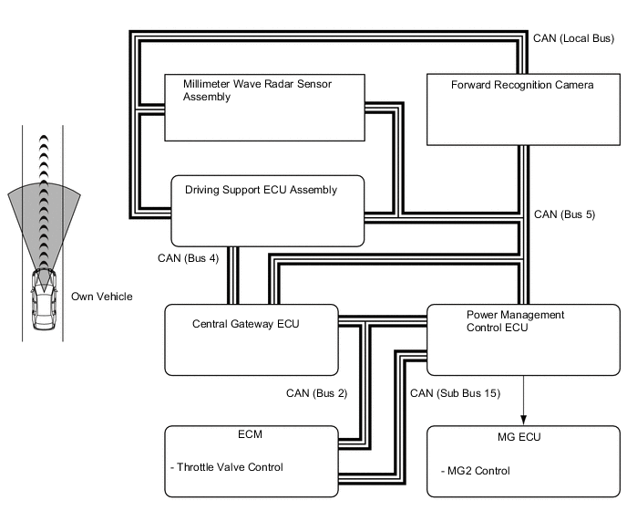
Constant Speed Control
-
The driving support ECU assembly compares the actual vehicle speed (wheel speed signal from the skid control ECU assembly) with the set vehicle speed under constant speed control mode. When the actual vehicle speed differs from the set vehicle speed, the driving support ECU assembly calculates the acceleration or deceleration required to achieve the set vehicle speed and transmits acceleration or deceleration request signals to the power management control ECU, thus optimally controlling the motive force and adjusting the actual vehicle speed to the set vehicle speed.
-
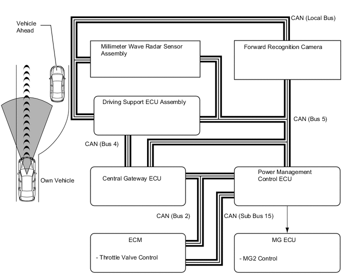
In vehicle-to-vehicle distance control mode, the driving support ECU assembly performs deceleration control, follow-up control, acceleration control, stop control*, stop retention control* or start control* based on the information about the vehicle ahead transmitted from the millimeter wave radar sensor assembly.
-
*: Models with full-speed following function
-
-
-
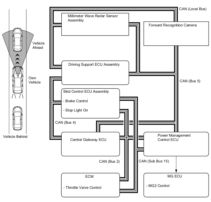
Deceleration Control
-
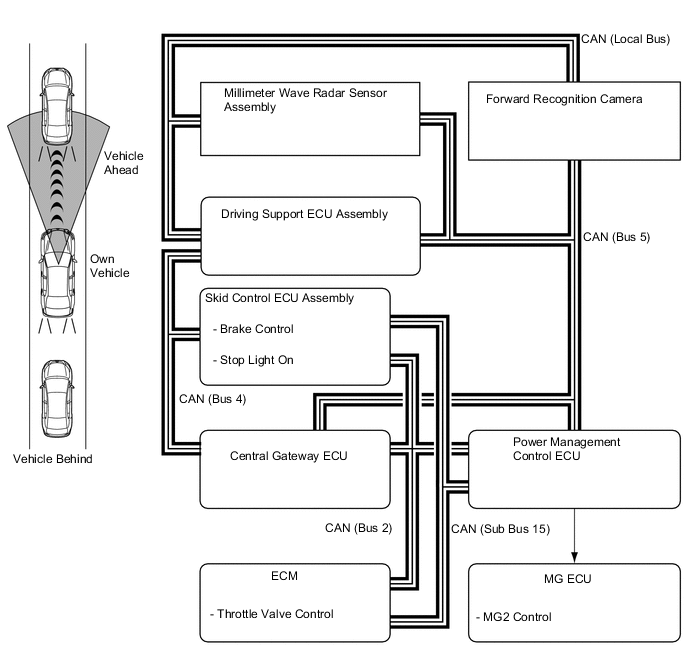
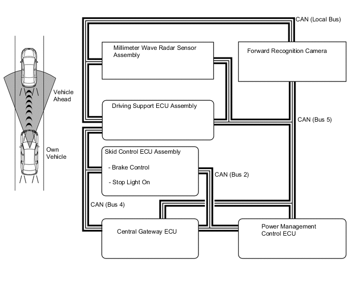
The driving support ECU assembly calculates the target deceleration rate in accordance with signals from the millimeter wave radar sensor assembly and forward recognition camera, and transmits a deceleration request signal to the power management control ECU. Upon receiving this signal, the power management control ECU controls the motive force and decelerate the vehicle in order to cause the vehicle to decelerate.
-
This control is not performed in the presence of a parked vehicle or object, or below the settable vehicle speed range.
-
When the power management control ECU determines that further deceleration is necessary, it transmits a brake request signal to the skid control ECU assembly. Upon receiving this signal, the skid control ECU assembly then activates the brake actuator assembly to apply the brakes.
-
At this time, if the deceleration rate is higher than a predetermined value, the skid control ECU assembly outputs a stop light illumination request signal, in order to inform anyone who might be following the vehicle.
-
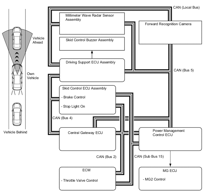
If the vehicle is not decelerating adequately, the driving support ECU assembly sounds the skid control buzzer assembly to urge the driver to depress the brake pedal.
-
-
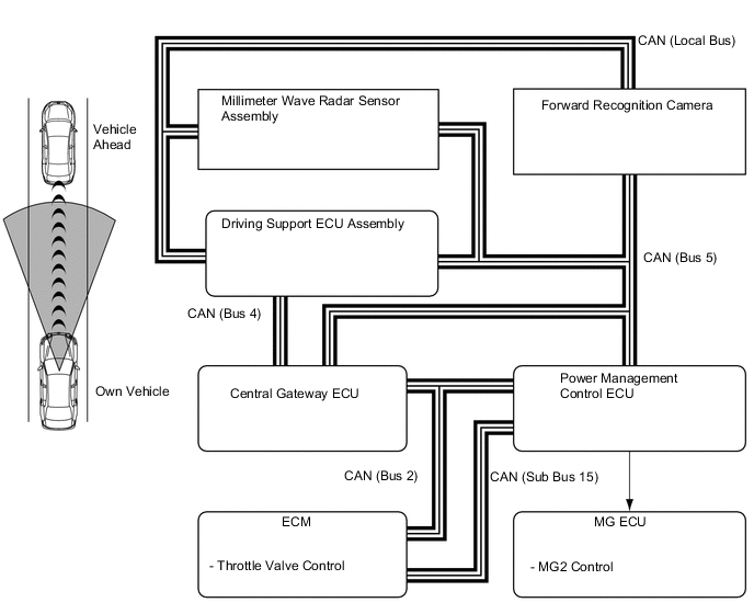
Follow-up Control
-
After performing deceleration control, the driving support ECU assembly transmits a acceleration or deceleration request signal to the power management control ECU, so that the vehicle can follow the vehicle ahead while maintaining a proper vehicle-to-vehicle distance in accordance with the vehicle speed. Upon receiving this signal, the power management control ECU controls the motive force in order to perform follow-up control.
-
3 stages (long, middle and short) of vehicle-to-vehicle distance can be selected by operating the vehicle-to-vehicle distance control switch.
-
-
Acceleration Control
-
When the driving support ECU assembly detects that either the vehicle ahead or own vehicle has changed lanes, a acceleration request signal is transmitted to the power management control ECU in order to attain the set vehicle speed. Upon receiving this signal, the power management control ECU controls the motive force in order to perform acceleration control.
-
-
Stop Control (Models with Full-speed Following Function)
-
The driving support ECU assembly detects if the vehicle ahead stops through the signals from the millimeter wave radar sensor assembly and forward recognition camera, and calculates the acceleration and deceleration required to stop the driver's own vehicle while maintaining an appropriate vehicle-to-vehicle distance. The driving support ECU assembly then transmits the acceleration and deceleration request signals to the power management control ECU. Upon receiving this signal, the power management control ECU controls the motive force and transmits a deceleration request signal to the skid control ECU assembly. Furthermore upon receiving deceleration request signal, the skid control ECU assembly controls the stop the vehicle.
-
At this time, the skid control ECU assembly outputs a stop light illumination request signal, in order to inform anyone who might be following the vehicle.
-
The distance between the driver's own vehicle and the preceding vehicle when the vehicles are stopped is set to approximately 3 m to 5 m (approximately 10 ft. to 16 ft.) regardless of the vehicle-to-vehicle distance preset by using the vehicle-to-vehicle distance control switch.
-
-
Stop Retention Control (Models with Full-speed Following Function)
-
After the vehicle has stopped under stop control, the power management control ECU transmits a stop retention request signal to the skid control ECU assembly. Upon receiving this signal, the skid control ECU assembly activates the brake hold function and keeps the vehicle stopped.
-
-
Start Control (Models with full-speed following function)
-
When the driving support ECU assembly detects that the vehicle ahead starts moving again from the millimeter wave radar sensor assembly and forward recognition camera signals, driving support ECU assembly displays the messages "PRECEDING VEHICLE MOVEMENT" and " Operate Cruise Lever or Accelerator Pedal to Resume " on the multi-information display to urge the driver to perform the start-off operation (to push the cruise control main switch to the +RES side or to depress the accelerator pedal).
-
On receiving the start-off operation signal generated by pushing the cruise control main switch to the +RES side or by depressing the accelerator pedal, the driving support ECU assembly transmits an acceleration and deceleration request signal to the power management control ECU. Upon receiving this signal, the power management control ECU controls the motive force, starts the vehicle and resumes follow-up control.
-
-
Automatic Cancel Control Function
-
When any of the conditions listed below occur while the vehicle is being driven using cruise control system, the cruise control system will be canceled. Then, the following warning items will appear for the driver.
Constant Speed Control Mode Description of Malfunction Warning Multi-information Display Master Warning Light Buzzer Cruise Control Indicator Light If the conditions listed below occur, the driving support ECU assembly clears the set vehicle speed and cancels the cruise control.
-
Stop light switch open or short circuit
The cruise control is prohibited until the conditions are remedied or the cruise control system is turned off and back on again using the ON-OFF button on the cruise control main switch.
Cruise Control Malfunction Visit Your Dealer Illuminates Sounds Once* - If the condition listed below occur, the driving support ECU assembly clears the set vehicle speed and cancels the cruise control.
-
Malfunction in the hybrid system
The cruise control is prohibited until the conditions are remedied or the cruise control system is turned off and back on again using the ON-OFF button on the cruise control main switch.
- - - - If the following condition occurs, the driving support ECU assembly clears the set vehicle speed and cancels the cruise control.
-
The vehicle speed drops more than 16 km/h (10 mph) below the set vehicle speed
- - - Illuminates If the condition listed below occurs, the driving support ECU assembly cancels speed control by the cruise control system while retaining the set vehicle speed in its memory.
-
The vehicle speed drops below low speed limit (approximately 40 km/h [25 mph]).
- - - Illuminates
-
*: Multi buzzer in the combination meter assembly sounds.
Vehicle-to-vehicle Distance Control Mode Description of Malfunction Warning Multi-information Display Master Warning Light Buzzer Radar Cruise Control Indicator Light If any of the conditions listed below occurs, the driving support ECU assembly clears the set vehicle speed and cancels the cruise control.
-
Stop light switch open or short circuit
The cruise control is prohibited until the conditions are remedied or the cruise control system is turned off and back on again using the ON-OFF button on the cruise control main switch.
Cruise Control Malfunction Visit Your Dealer Illuminates Sounds Once*3 - Cruise Control Fault Press Brake to Deactivate Visit Your Dealer*2 Sounds until the brake pedal is depressed*2*4 If any of the conditions listed below occur, the driving support ECU assembly clears the set vehicle speed and cancels speed control by the cruise control system.
-
Malfunction of the millimeter wave radar sensor assembly
-
Misalignment of the axis of the millimeter wave radar sensor assembly
-
Malfunction of the brake hold function*1
-
Malfunction in the dynamic radar cruise control system other than those given above
The cruise control is disabled until the power switch is turned on (IG) again.
Cruise Control Malfunction Visit Your Dealer Illuminates Sounds Once*3 - Cruise Control Fault Press Brake to Deactivate Visit Your Dealer*2 Sounds until the brake pedal is depressed*2*4 If the condition listed below occurs, the driving support ECU assembly cancels speed control by the cruise control system while retaining the set vehicle speed in its memory.
-
The millimeter wave radar sensor assembly or the emblem are dirty
The cruise control is disabled until the condition is corrected or the cruise control system is turned off and back on again using the ON-OFF button on the cruise control main switch
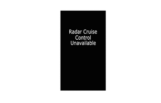
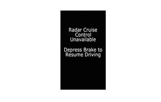
Radar Cruise Control Unavailable Clean Sensor Illuminates Sounds Once*3 - Cruise Control Fault Press Brake to Deactivate Visit Your Dealer*2 Sounds until the brake pedal is depressed*2*4 If either of the conditions listed below occurs, the driving support ECU assembly cancels speed control by the cruise control system while retaining the set vehicle speed in its memory.
-
The measurement becomes extremely unstable due to poor weather conditions
-
When the radar cruise control system temporarily can not use the brake system.
-
The beam axis of the millimeter wave radar sensor assembly is being aligned.
-
Forward recognition camera temporarily not available
-
A malfunction in the forward recognition camera
The cruise control is disabled until the condition is corrected or the cruise control system is turned off and back on again using the ON-OFF button on the cruise control main switch.
Radar Cruise Control Unavailable Illuminates Sounds Once*3 - Cruise Control Fault Press Brake to Deactivate Visit Your Dealer*2 Sounds until the brake pedal is depressed*2*4 If the condition listed below occurs, the driving support ECU assembly cancels speed control by the cruise control system while retaining the set vehicle speed in its memory.
-
The vehicle speed drops below the low speed limit (approximately 40 km/h [25 mph]) (When there is no vehicle ahead*1)
Radar Cruise Control Unavailable Illuminates Sounds Once*3 - During stop retention control, If the condition listed below occurs, the driving support ECU assembly cancels speed control by the cruise control system.*2
-
The driver seat belt is unfastened.
-
The driver door is opened.
-
The vehicle is parked for a long period of time.
-
The vehicle is driving on as steep hill.
Cruise Control Fault Press Brake to Deactivate Visit Your Dealer Illuminates Sounds until the brake pedal is depressed*4 - Tech Tips
*1: Models with full-speed following function
*2: During stop retention control (models with full-speed following function)
*3: Multi buzzer in the combination meter assembly sounds.
*4: Skid control buzzer assembly sounds.
-
-
-
-
CONSTRUCTION
-
Cruise Control Main Switch
-
The cruise control main switch consists of the ON-OFF button and the +RES, -SET and CANCEL switches. The +RES, -SET and CANCEL switches are operated by moving the lever in the 3 directions indicated.
-
The switches in the cruise control main switch are of the automatic reset (normally open) type that turn on only when the switch is being operated and turn off as soon as the driver releases the switch. Furthermore, the functions of the switches are active only when the cruise control system has been turned on using the ON-OFF button on the cruise control main switch.
-
When the cruise control system is turned on using the ON-OFF button, the system starts in vehicle-to-vehicle distance control mode. When the ON-OFF button is pressed and held for 1.5 seconds or more, the system changes to constant control mode.
-
-
Vehicle-to-vehicle Distance Control Switch
-
While the vehicle is being driven in vehicle-to-vehicle distance control mode, the vehicle-to-vehicle distance setting changes as follows each time the distance control switch is pressed: long → middle → short.
-
If the ignition switch is turned off and back ON, the system will default to "long".
-
The vehicle-to-vehicle distance is as follows:
Mode Vehicle-to-vehicle Distance* Long Approx. 50 m (160 ft.) Middle Approx. 40 m (130 ft.) Short Approx. 30 m (100 ft.) Tech Tips
*: While driving at a speed of 80 km/h (50 mph).
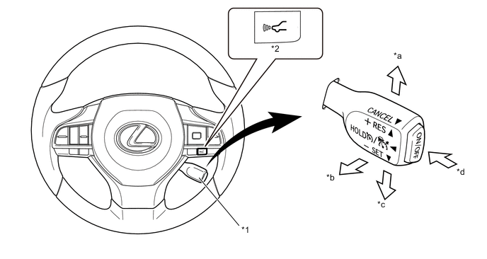
Text in Illustration *1 Vehicle-to-vehicle Distance Control Switch *2 Cruise Control Main Switch *a +RES Switch *b CANCEL Switch *c -SET Switch *d ON-OFF Button
-
-
Millimeter Wave Radar Sensor Assembly
-
The millimeter wave radar sensor assembly consists of a millimeter wave radar circuit, signal processing circuit, and CPU.
-
The millimeter wave radar outputs waves when the vehicle speed is above 0 km/h (0 mph), and not when the vehicle speed is at 0 km/h (0 mph). The millimeter wave radar uses frequencies in the 76.5 GHz band.
-
The reception antennas receive the millimeter wave radar waves that have been reflected.
-
The signal processing circuit detects the distance, relative speed, and the direction of the object by generating millimeter wave radar waves and calculating the signals received by the reception antennas. Then, it transmits this information to the driving support ECU.
-
-
Forward Recognition Camera
-
Forward recognition camera is mounted in the upper center of the windshield glass. The sensor detects vehicles and other objects on the road ahead using the image captured by the built-in monocular camera and determines their distance. With this, the recognition performance and reliability of the dynamic radar cruise control system has been enhanced.
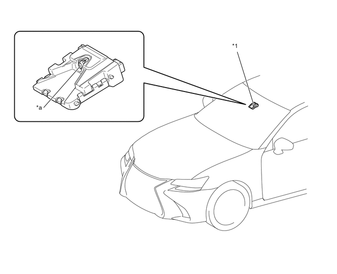
Text in Illustration *1 Forward Recognition Camera - - *a Monocular Camera - -
-
-
Camera Heater (Forward Recognition Hood with Heater Sub-assembly) (Models with Camera Heater)
-
The camera heater, which is installed between the forward recognition camera and windshield glass, is heated according to signals from the forward recognition camera in order to prevent the windshield glass on the front of the forward recognition camera from fogging, and also to remove fog buildup. For details, see the PRE-CRASH SAFETY SYSTEM section.
-
-
-
OPERATION
-
Combination Meter Assembly
-
The combination meter assembly provides a master warning light, cruise control indicator light, radar cruise control indicator light, cruise control SET indicator light, multi buzzer, and multi-information display to provide warnings and messages regarding the dynamic radar cruise control system.
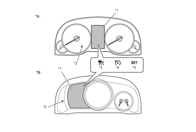
Text in Illustration *A Except F SPORT *B F SPORT *1 Multi-information Display *2 Master Warning Light *3 Radar Cruise Control Indicator Light *4 Cruise Control Indicator Light *5 Cruise Control SET Indicator Light - - -
The multi-information display displays the set vehicle speed, vehicle ahead mark, vehicle-to-vehicle distance mark and warning message.
-
Examples are shown below for the illumination or display of each indicator light, warning light or multi-information display:
Constant Speed Control Mode Condition Multi-information Display Master Warning Light Buzzer Display Image Cruise Control Indicator Light Cruise Control SET Indicator Light Set standby - Illuminates - - - Being controlled*1 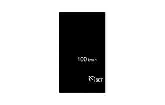
Illuminates Illuminates - - Malfunction occurred 
- - - Sounds Once*2 Tech Tips
*1: While driving at a set speed of 100 km/h (62 mph).
*2: Multi buzzer in the combination meter assembly sounds.
Vehicle-to-vehicle Distance Control Mode Condition Multi-information Display Master Warning Light Buzzer Display Image Radar Cruise Control Indicator Light Cruise Control SET Indicator Light Precaution display (displayed for 6 sec. after ON-OFF button has been turned on.) 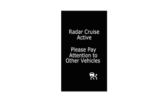
Illuminates - - - Set standby 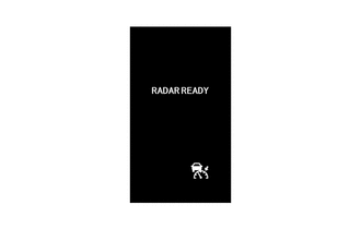
Illuminates - - - Being controlled*1 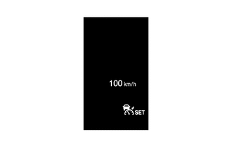
Illuminates Illuminates - - Under constant speed control (no vehicle ahead)*1 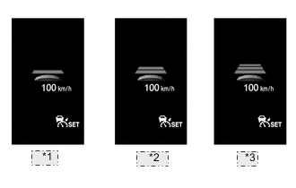
*1 Short *2 Middle *3 Long Illuminates Illuminates - - Under follow-up control (preceding vehicle)*1 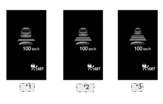
*1 Short *2 Middle *3 Long Illuminates Illuminates - - Under follow-up control (the vehicle ahead moves away when the vehicle is being driven at approx. 40 km/h [25 mph] or less.)*2 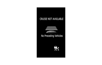
Illuminates - - - Deceleration control (vehicle ahead)*1 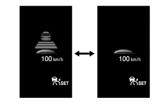
Illuminates Illuminates - Sounds continuously*3 The vehicle-to-vehicle distance mark and vehicle ahead mark blinks and the skid control buzzer assembly sounds. Stop retention control*1,*2 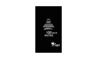
Illuminates Illuminates - - Start control*2 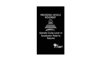
Illuminates Illuminates - - The millimeter wave radar sensor assembly or the emblem are dirty 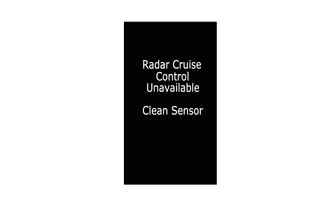
- - Illuminates Sounds Once*4
-
Poor Weather Conditions
-
Malfunction in the forward recognition camera
-
The beam axis of the millimeter wave radar sensor assembly is being aligned.
-
The forward recognition camera is temporarily unavailable
- - Illuminates Sounds Once*4 Malfunction occurred - - Illuminates Sounds Once*4 Malfunction occurred during stop retention control*2 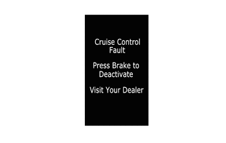
- - Illuminates Sounds continuously*3 The skid control buzzer assembly sounds until the brake pedal is depressed. When any problem occurs during stop retention control, or any of the following conditions is met:*2
-
The driver seat belt is unfastened
-
The driver door is opened
-
The vehicle is parked for a long period of time
-
The vehicle is driving on a steep hill
-
A preceding vehicle is not detected
- - Illuminates Sounds continuously*3 The skid control buzzer assembly sounds until the brake pedal is depressed. Tech Tips
*1: While driving at a set speed of 100 km/h (62 mph).
*2: Models with full-speed range following function.
*3: Skid Control buzzer assembly sounds.
*4: Multi buzzer in the combination meter assembly sounds.
Headup Display (Models with Headup Display) Condition Display Approach warning (Vehicle Ahead)* 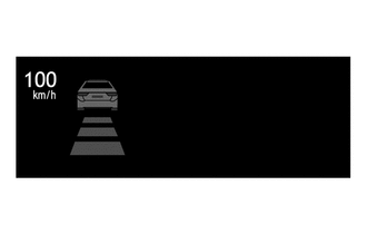
The vehicle-to-vehicle distance mark and vehicle ahead mark blinks.
-
*: While driving at a set speed of 100 km/h (62 mph).
-
-
-