LUBRICATION SYSTEM
-
CONSTRUCTION
-
Oil Pump
-
A trochoid gear type oil pump directly driven by the crankshaft is used.
-
This oil pump uses an internal relief method which circulates relief oil to the suction passage in the oil pump assembly. This aims to minimize the oil level change in the oil pan assembly, reduce friction, and reduce the air mixing rate in the oil.
-
-
Oil Strainer Sub-assembly
-
The oil strainer structure has been divided into 2 parts; the oil strainer sub-assembly and the oil pump inlet pipe sub-assembly. By utilizing resin composite material, both the oil strainer sub-assembly and the oil pump inlet pipe sub-assembly have been made lightweight and compact, and the overall engine height has been decreased. In addition, by optimizing the cross-sectional area of the oil strainer inner passage, pressure loss has also been reduced.
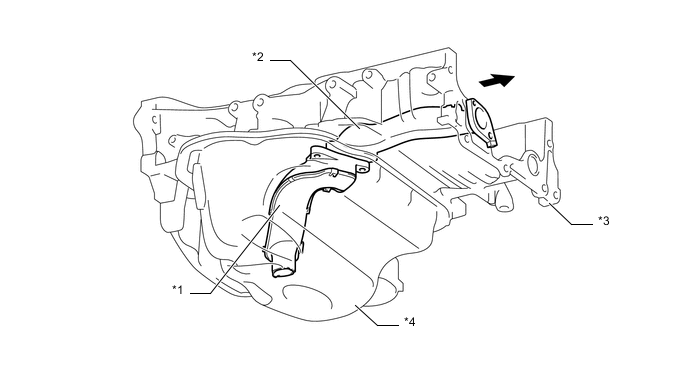
Text in Illustration *1 Oil Strainer Sub-assembly *2 Oil Pump Inlet Pipe Sub-assembly *3 Stiffening Crankcase Assembly *4 Oil Pan Sub-assembly 
Engine Front Side - -
-
-
Oil Nozzle Sub-assembly
-
Oil nozzle sub-assemblies are provided on the left side of the cylinder block sub-assembly for cooling and lubricating the pistons.
-
Each No. 2 oil nozzle sub-assembly contains a check ball to prevent oil from being fed when the oil pressure is low. This prevents the overall oil pressure in the engine from dropping.
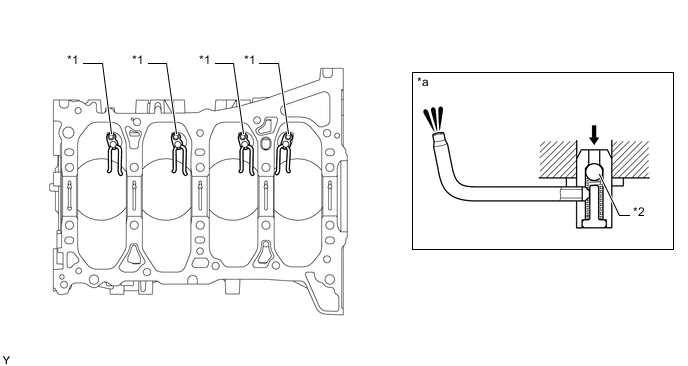
Text in Illustration *1 No. 2 Oil Nozzle Sub-assembly *2 Check Ball *a Oil Nozzle Sub-assembly Cross Section - - Oil - -
-
-
Oil Filter
-
An oil filter with a replaceable oil filter element is used. The oil filter element uses a high performance filter paper to improve filtration performance. It is also combustible for environmental protection.
-
A plastic oil filter cap is used for weight reduction.
-
This oil filter has a structure which can allow draining of the oil remaining in the oil filter. This prevents oil from spattering when replacing the element and allows the technician to work without touching hot oil.
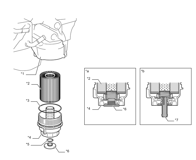
Text in Illustration *1 Stiffening Crankcase Assembly *2 Element *3 Oil Filter Cap Gasket *4 Oil Filter Cap Assembly *5 O-ring *6 Oil Filter Drain Plug *7 Drain Pipe - - *a Oil Filter Cross Section *b When Draining Oil
-
-