LANE DEPARTURE ALERT SYSTEM
-
FUNCTION OF MAIN COMPONENTS
Components Function Combination Meter Assembly LDA Indicator Light Illuminates or turns off in accordance with signals from the forward recognition camera. Multi-information Display Displays a warning message and white lines to inform or warn the driver of the system condition in accordance with signals from the forward recognition camera. Master Warning Light Illuminates to warn the driver in accordance with signals from the forward recognition camera. Multi Buzzer Sounds to warn the driver in accordance with signals from the forward recognition camera. Forward Recognition Camera
-
Captures the road view ahead of the vehicle and detects lane markers on the driving lane, and calculates the radius to the center of the lane, lane width, distance from markers and heading angle deviation.
-
Controls the LDA system.
-
Transmits the indicator illumination request signal, multi-information display indication light request signal, steering vibration and buzzer sound request signal to the combination meter assembly.
-
Receives vehicle information and turn signal light operation signals and sends a steering force signal to the power steering ECU assembly.
-
Transmits an operation signal to the camera heater.*1
Camera Heater (Forward Recognition Hood with Heater Sub-assembly)*1 The camera heater is heated according to signals from the forward recognition camera. Millimeter Wave Radar Sensor Assembly Radiates millimeter radar waves forward, uses the reflected waves to detect the presence of a vehicle traveling ahead, the vehicle-to-vehicle distance, and the relative speed, and then transmits this information to the forward recognition camera. Driving Support ECU Assembly Transmits the LDA main switch signal to the forward recognition camera. Power Management Control ECU Sends the accelerator pedal opening angle signal to the forward recognition camera. Headlight Dimmer Switch Assembly Transmits a turn signal command to the combination meter assembly. Skid Control ECU Assembly Sends a vehicle speed signal from the speed sensor to the forward recognition camera. Steering Pad Switch Assembly LDA Main Switch Detects an on/off status of the system and transmits a signal to the driving support ECU assembly. Meter Control Switch Changes the customize settings of the lane departure alert function, lane departure control function and vehicle sway warning function. Yawrate Sensor Detects yaw rate and transmits a signal to the forward recognition camera. Steering Sensor Sends the turning angle of the steering wheel to the forward recognition camera. Power Steering ECU Assembly Controls the power steering motor and performs steering assist based on signals received from the forward recognition camera. Steering Vibration and Heater ECU*2 or Steering Vibration ECU*3 Controls the steering vibration according to signals from the forward recognition camera. Combination Meter Mirror ECU*4 Shows the lane departure warning display in accordance with a signal from the combination meter assembly. Speed Sensors Detects the wheel speed of each of the 4 wheels and outputs it to the skid control ECU assembly. Rear Steering Control ECU*5 Sends the state of dynamic rear steering system to the forward recognition camera. Main Body ECU (Multiplex Network Body ECU) Sends country specification information signals to the forward recognition camera. Central Gateway ECU Gateway function of CAN communication. *1: Models with camera heater
*2: Models with heated steering wheel system
*3: Models without heated steering wheel system
*4: Models with headup display
*5: Models with Lexus dynamic handling system
-
-
OPERATING CONDITION
-
Operating Conditions of LDA System (Lane Departure Alert Function)
Operation Condition Operating/Resume The lane departure alert function is activated when all of the following conditions are met:
-
The LDA main switch is on. (When the LDA main switch is pressed to turn on the LDA system, the LDA indicator light illuminates.)
-
The vehicle speed is between approximately 50 km/h (32 mph) or more.
-
Lane markers are detected.
-
No turn signal command is detected.
-
System malfunction is not detected.
Suspended The lane departure alert function is suspended when any one of the following conditions is met:
-
The vehicle speed is less than approximately 50 km/h (32 mph).
-
A turn signal command is detected.
-
No lane markers are detected.
-
Immediately after the lane departure alert is activated.
-
A malfunction is detected in the LDA system.
-
The temperature of the forward recognition camera is abnormal.
-
The vehicle crosses halfway or further over a lane marker.
Canceled The lane departure alert function is stopped when any one of the following conditions is met:
-
The LDA main switch is off.
-
The LDA system is malfunctioning.
-
The LDA system is temporarily stopped.
-
The power switch is turned off.
The lane departure alert function resumes when the following conditions are met:
-
The conditions to start operation listed above returns to are satisfied.
-
The LDA system condition returns to normal.
-
The power switch is turned off and on (IG) again to ensure normal operation, after the LDA system has been stopped by a system malfunction.
-
-
Operating Conditions of LDA System (Steering Assist Function)
Operation Condition Operating/Resume The steering assist function is activated when all of the following conditions are met:
-
The LDA main switch is on. (When the LDA main switch is pressed to turn on the LDA system, the LDA indicator light illuminates.)
-
The vehicle speed is between approximately 50 km/h (32 mph) or more.
-
Lane markers are detected.
-
No turn signal command is detected.
-
System malfunction is not detected.
-
The steering assist is turned on using a meter control switch.
-
Deceleration at or above a constant speed is not detected.
-
Steering operations to change the direction of vehicle travel are not performed.
-
Systems related to vehicle safety, such as the VSC and pre-crash safety system, do not operate.
-
Acceleration via operation of the accelerator pedal is not detected.
-
Hands off steering wheel alert is not displayed.
Suspended The steering assist function is suspended when any one of the following conditions is met:
-
The vehicle speed is less than approximately 50 km/h (32 mph).
-
A turn signal command is detected.
-
No lane markers are detected.
-
Immediately after the lane departure alert is activated.
-
Yawrate sensor is malfunctioning.
-
A malfunction is detected in the LDA system.
-
The steering sensor is malfunctioning.
-
The temperature of the forward recognition camera is abnormal.
-
The vehicle crosses halfway or further over a lane marker.
-
Steering assist generated to change the direction of vehicle travel is detected.
-
Deceleration at or above a constant speed is detected.
-
Systems related to vehicle safety, such as the VSC and pre-crash safety system, operate.
-
Acceleration via operation of the accelerator pedal is detected.
-
No steering wheel operation detected.
Canceled The steering assist function is stopped when any one of the following conditions is met:
-
The LDA main switch is off.
-
The LDA system is malfunctioning
-
The LDA system is temporarily stopped.
-
The power switch is turned off.
-
The steering assist is turned off using a meter control switch.
The steering assist function resumes when the following conditions are met:
-
The conditions to start operation listed above returns to are satisfied.
-
The LDA system condition returns to normal.
-
The power switch is turned off and on (IG) again to ensure normal operation, after the LDA system has been stopped by a system malfunction.
-
The steering assist is turned on using a meter control switch.
-
-
Operating Conditions of LDA System (Sway Warning System)
Operation Condition Operating/Resume The sway warning system is activated when all of the following conditions are met:
-
The vehicle speed is above approximately 50 km/h (32 mph) or more.
-
Lane markers are detected.
-
System malfunction is not detected.
-
The sway warning is turned on using a meter control switch.
Suspended The sway warning system is suspended when any one of the following conditions is met:
-
The vehicle speed is not approximately 50 km/h (32 mph) or more.
-
A turn signal command is detected.
-
No lane markers are detected.
-
Immediately after the lane departure alert is activated.
Canceled The sway warning system is stopped when any one of the following conditions is met:
-
The LDA system is malfunctioning.
-
The sway warning is turned off using a meter control switch.
The sway warning system resumes when the following conditions are met:
-
The conditions to start operation listed above returns to are satisfied.
-
The LDA system condition returns to normal.
-
The power switch is turned off and on (IG) again to ensure normal operation, after the LDA system has been stopped by a system malfunction.
-
-
-
SYSTEM CONTROL
-
LDA System Warning Operation
-
Function Over View (Lane Departure Alert Function)
-
If the function judges that the vehicle may deviate from the lane it is in, the function illuminates the indicator in the combination meter display and vibrates the steering wheel or sounds a buzzer so that the driver can take action to avoid lane departure.
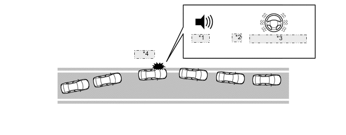
*1 Buzzer *2 or *3 Steering Vibration *4 Warning
-
-
Function Over View (Steering Assist Function)
-
If the function judges that the vehicle may deviate from the lane it is in, the function performs steering assist to help the driver correct the path of the vehicle. If the driver does not take appropriate action, the system vibrates the steering wheel or sound a buzzer.
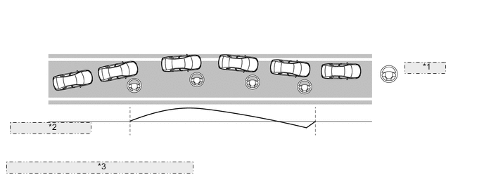
*1 Steering Assist *2 Control output level *3 Example of vehicle behavior and control output
-
-
Function Over View (Sway Warning System)
-
The system detects drift of the vehicle within its lane, which is often the result of a driver who is tired, distracted or not looking ahead, based on the position of the vehicle within its lane and the steering inputs of the driver, and alerts the driver before a lane departure or collision occurs.
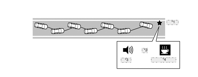
*1 Warning *2 and *3 Buzzer *4 Warning Display
-
-
-
-
FUNCTION
-
Using the meter control switch of the steering pad switch assembly, the LDA system settings functions and the sway warning functions can be customized.
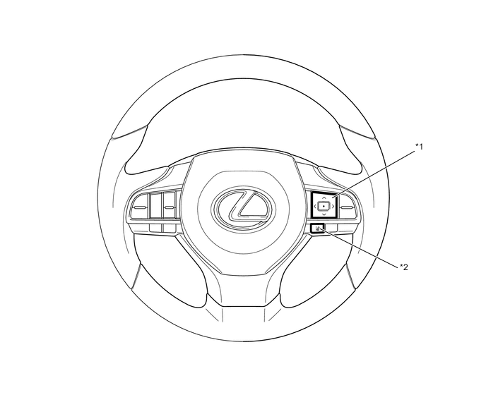
Text in Illustration *1 Meter Control Switch *2 LDA Main Switch -
Customize LDA system Settings Functions
Item (Select using the up/down button of the meter control switch) Description Setting (Change using the center button of the meter control switch) Steering Assist Select to on/off steering wheel assistance
-
ON
-
OFF
Warning Sensitivity Timing of lane departure warning
-
Normal
-
High
Alert Warning Method
-
Buzzer
-
Steering Vibration
-
-
Customize Sway Warning Functions
Item (Select using the up/down button of the meter control switch) Description Setting (Change using the center button of the meter control switch) Sway Warning Select to on/off the sway warning system.
-
ON
-
OFF
Sway Sensitivity Timing of sway warning
-
High
-
Normal
-
Low
-
-
-
OPERATION
-
Combination Meter Assembly
-
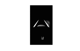
The combination meter assembly illuminates the indicator lights or displays an indicator on the multi-information display and sounds a multi buzzer (which is built into the combination meter assembly) in accordance with the respective condition.
Condition Multi-information Display* LDA Indicator Light Multi Buzzer Steering assist off 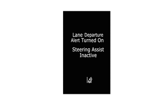
Illuminates (White) - Steering assist on 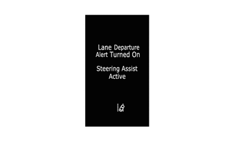
Illuminates (White) -
-
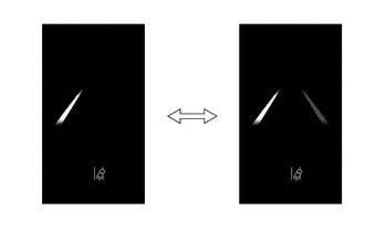
Steering assist unavailable
-
Lane markers detected
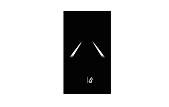
Illuminates (White) -
-
Steering assist available
-
Lane markers detected
Illuminates (White) -
-
Steering assist available
-
One lane marker detected

Illuminates (White) -
-
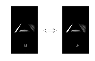
Steering assist unavailable
-
Lane markers not detected
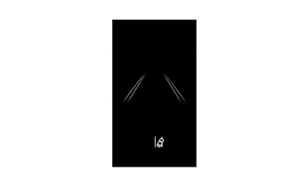
Illuminates (White) -
-
Steering assist operating
-
Lane markers detected
Illuminates (Green) -
-
Steering assist available
-
Lane markers detected
-
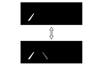
Lane departure alert operating
Blinks (Amber) Sounds The lane marker icons blink
-
Steering assist operating
-
Lane departure alert operating
-
Lane markers detected
Blinks (Amber) Sounds The lane marker icons blink
-
*: These illustrations are examples.
Warning Messages Condition Multi-information Display*1 Master Warning Light Multi Buzzer System malfunction 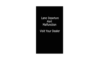
Illuminates Sounds Sensor malfunction 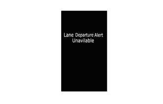
Illuminates Sounds LDA main switch is turned on at approximately 50 km/h (32 mph) or lower 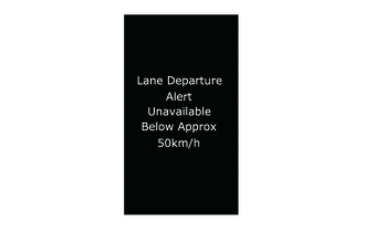
- - Vehicle decelerates to below operating
-
Displayed once after the power switch is turned to on (IG).
With LDA main switch is on (steering assist available), No hands are detected on steering Wheel. 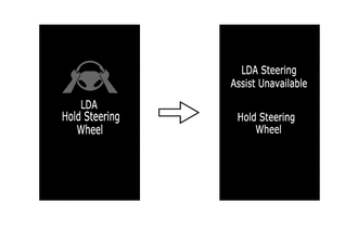
Illuminates*2 Sounds*2
-
*1: These illustrations are examples.
-
*2: When display changes
-
-
-
Headup Display (Models with Headup Display)
-
The headup display displays the lane departure alert function. During the operation of the lane departure alert function, the lane marker icons blink.
Condition Display* Lane markers detected 
One lane marker detected 
-
Lane markers detected
-
Lane departure alert operating
The lane marker icons blink.
-
*: These illustrations are examples.
-
-
-
-
CONSTRUCTION
-
Forward Recognition Camera
-
The forward recognition camera captures the road image up to approximately 50 m (164 ft.) ahead of the forward recognition camera.
-
The forward recognition camera detects lane markers and calculates the radius to the center of the lane, the vehicle center position disparity among the distances from each left and right lane marker and the angle disparity between the vehicle traveling direction and each left and right lane marker.
-
When one of the following operations is conducted, the forward recognition camera angle must be adjusted. For details, refer to the Repair Manual.
-
The forward recognition camera is removed and reinstalled or replaced.
-
Parts relating to the tire or suspension are replaced or adjusted.
-
Strong force is applied onto the forward recognition camera.
-
-
The LDA system does not operate if the vehicle approaches the lane marker (but does not cross it), as long as the vehicle remains parallel with the lane marker.
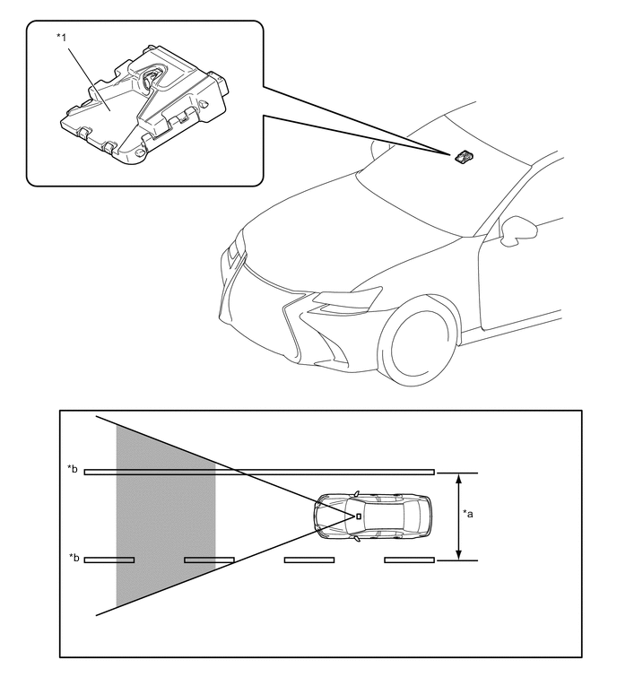
Text in Illustration *1 Forward Recognition Camera - - *a Approximately 3.0 m (9.8 ft.) or more *b Lane Marker 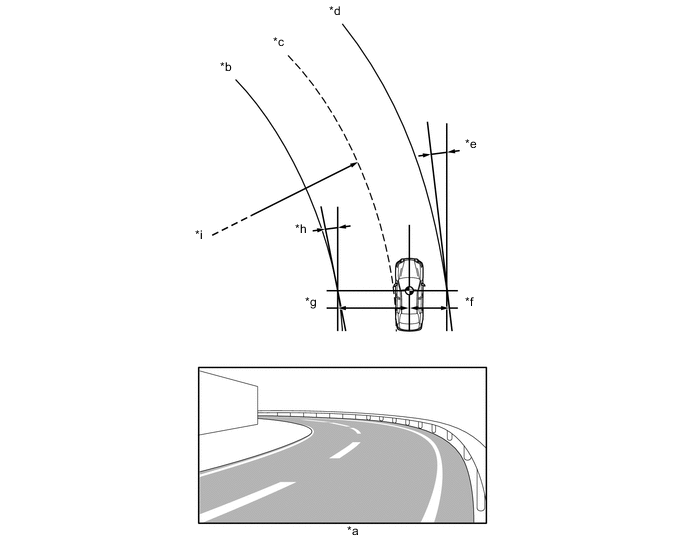
Text in Illustration *a Image Captured by Forward Recognition Camera *b Left Lane Marker *c Center of Lane *d Right Lane Marker *e Angle between the Vehicle Traveling Direction and Right Lane Marker *f Distance from the Vehicle to Right Lane Marker *g Distance from the Vehicle to Left Lane Marker *h Angle between the Vehicle Traveling Direction and Left Lane Marker *i Lane Radius (If only the left lane marker or right lane marker is recognized, the radius of the recognized lane marker will be calculated.) - -
-
-
Camera Heater (Forward Recognition Hood with Heater Sub-assembly) (Models with Camera Heater)
-
The camera heater, which is installed between the forward recognition camera and windshield glass, is heated according to signals from the forward recognition camera in order to prevent the windshield glass on the front of the forward recognition camera from fogging, and also to remove fog buildup. For details, see the PRE-CRASH SAFETY SYSTEM section.
-
-
-
DIAGNOSIS
-
If a malfunction is detected in the LDA system the forward recognition camera cancels the LDA system, Illuminates the LDA indicator light in yellow and illuminates the master warning light, sounds the multi buzzer in the combination meter assembly, and displays a message on the multi-information display to inform the driver of the malfunction.
-
At the same time, the malfunction is stored in memory as a Diagnostic Trouble Code (DTC). When a Global TechStream (GTS) is connected to the DLC3, the DTC can be read. For details, refer to the Repair Manual
-