SFI SYSTEM
-
FUNCTION OF MAIN COMPONENTS
-
The main components of the engine control system are as follows:
Component Outline Quantity Function ECM 32-bit CPU 1 The ECM optimally controls the SFI, ESA and ISC to suit the operating conditions of the engine in accordance with the signals provided by the sensors. Intake Mass Air Flow Meter Sub-assembly Hot-wire Type 1 This sensor has a built-in hot-wire to directly detect the intake air mass. Intake Air Temperature Sensor Thermistor Type 1 This sensor detects the intake air temperature by means of an internal thermistor. Engine Coolant Temperature Sensor Thermistor Type 1 This sensor detects the engine coolant temperature by means of an internal thermistor. Fuel Pressure Sensor Semiconductor Type 1 The sensor senses the fuel pressure in the delivery pipe. Crankshaft Position Sensor
[Rotor Teeth]
Pick-up Coil Type [36 - 2] 1 This sensor detects the engine speed. Camshaft Position Sensors for Intake
[Rotor Teeth]
Magnetic Resistance Element (MRE) Type [3] 2 (1 each bank) Theses sensors are used to detect the camshaft position. Camshaft Position Sensors for Exhaust
[Rotor Teeth]
Magnetic Resistance Element (MRE) Type [3] 2 (1 each bank)
-
Theses sensors are used to detect the camshaft position.
-
Theses sensors perform cylinder identification.
Vacuum Sensor Semiconductor Silicon Chip Type 1 This sensor uses built-in semiconductors to detect the intake air surge tank pressure. Throttle Position Sensor Linear (Non-contact) Type 1 This sensor detects the throttle valve opening angle. Knock Control Sensors 1 and 2 Built-in Piezoelectric Type
(Non-resonant Type/Flat Type)
2 (1 each bank) Theses sensor detect an occurrence of the engine knocking indirectly from the vibration of the cylinder block caused by the occurrence of engine knocking. Air Fuel Ratio Sensors
(Bank 1, Sensor 1)
(Bank 2, Sensor 1)
Heated Type (Planar Type) 2 (1 each bank) As with the oxygen sensor, these sensors detect the oxygen concentration in the exhaust emissions. However, they detect the oxygen concentration in the exhaust emissions linearly. Oxygen Sensors
(Bank 1, Sensor 2)
(Bank 2, Sensor 2)
Heated Type (Cup Type) 2 (1 each bank) Theses sensor detect the oxygen concentration in the exhaust emissions by measuring the electromotive force which is generated in the sensors themselves. Fuel Injector Assemblies
(for Direct Injection)
High Pressure Slit Nozzle Type 6 Theses injectors contains a high-pressure electromagnetically-operated nozzle to inject fuel directly into the cylinder. Fuel Injector Assemblies
(for Port Injection)
12-hole Type 6 Theses injectors are electromagnetically-operated nozzles which injects fuel in accordance with signals from the ECM. Solenoid Valve Assembly 1-hole Type 1 Applies current to the coils based on a signal from the ECM and returns fuel to the fuel tank assembly. EDU (Injector Driver) Built-in DC/DC Converter 1 The EDU converts the signals from the ECM into high-voltage, high-amperage current in order to drive the direct injection injectors. -
-
-
SYSTEM CONTROL
-
The engine control system has the following features and the ECM controls these systems:
System Outline Direct Injection 4-stroke Gasoline Engine Superior Version Sequential Multiport Fuel Injection (D-4S SFI)
-
This is an L-type SFI system. It directly detects the intake air mass with a hot wire type intake mass air flow meter sub-assembly.
-
This system is a fuel injection system which combines direct injection injectors and port injection injectors.
-
Based on signals from each sensor, the ECM controls the injection volume and timing of each type of injector (direct and port injection types) in accordance with the engine speed and engine load in order to optimize combustion conditions.
Electronic Spark Advance (ESA)
-
Ignition timing is determined by the ECM based on signals from various sensors. The ECM corrects ignition timing in response to engine knocking.
-
This system selects the optimal ignition timing in accordance with the signals received from the sensors and sends (IGT) ignition signals to the igniters.
Electronic Throttle Control System-intelligent (ETCS-i) Calculates the opening of the throttle in accordance with driving conditions, corrects it based on a signal from each sensor and controls it properly. Dual Variable Valve Timing-intelligent (Dual VVT-i) Controls the intake and exhaust camshafts to an optimal valve timing in accordance with engine operating conditions. Engine Speed Control The power management control ECU controls the engine speed via the ECM in accordance with the vehicle speed and the amount the accelerator pedal is depressed in order to optimize the fuel consumption of the HV system. At that moment, by performing corrections according to the engine output change due to the usage environment, the engine may control its own speed using the throttle in accordance with vehicle conditions. Fuel Pump Control For High-pressure Pump Regulates the fuel pressure within a range of 2.4 to 18 MPa in accordance with driving conditions. For Low-pressure Pump
-
Based on signals from the ECM, the fuel pump control ECU controls the fuel pump.
-
The fuel pump is stopped when a Supplemental Restraint System (SRS) airbag is deployed.
Cooling Fan Control The cooling fan ECU steplessly controls the speed of the fans in accordance with the engine coolant temperature, vehicle speed, engine speed, and air conditioning operating conditions. As a result, the cooling performance is improved. Air Fuel Ratio Sensor and Oxygen Sensor Heater Control Maintains the temperature of the air fuel ratio sensors or oxygen sensors at an appropriate level to increase the ability of the sensors to accurately detect the oxygen concentration. Fail-safe When the ECM detects a malfunction, it stops or controls the engine according to the data already stored in memory. Diagnosis When the ECM detects a malfunction, it records the malfunction and information that relates to the fault. -
-
-
FUNCTION
-
Direct Injection 4-stroke Gasoline Engine Superior Version Sequential Multiport Fuel Injection (D-4S SFI) System
-
The D-4S SFI system directly detects the intake air mass with a hot-wire type intake mass air flow meter sub-assembly.
-
The D-4S SFI system is a fuel injection system which combines direct injection injectors and port injection injectors.
-
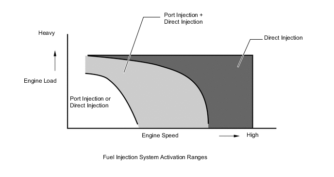
Based on signals from each sensor, the ECM controls the injection volume and timing of each type of fuel injector (direct and port injection types) in accordance with engine load and engine speed in order to optimize combustion conditions.
-
To promote warm-up of the catalyst after a cold engine start, this system uses a stratified air-fuel mixture. This creates an area near the spark plug that is richer than the rest of the air-fuel mixture. This also allows a greater amount of ignition timing retard to be used, raising the exhaust gas temperature. The increased exhaust gas temperatures promote rapid warm-up of the catalysts, significantly reducing exhaust emissions.
-
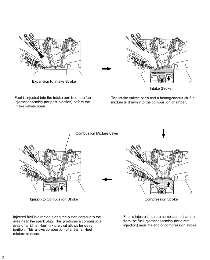
Stratified Combustion: To achieve stratified combustion, immediately after a cold engine start, fuel is injected into the intake port from the fuel injector assembly (for port injection) during the exhaust stroke. Fuel is also injected from the fuel injector assembly (for direct injection) near the end of the compression stroke. This results in an air-fuel mixture that is stratified, and the area near the spark plug richer than the rest of the air-fuel mixture.
-
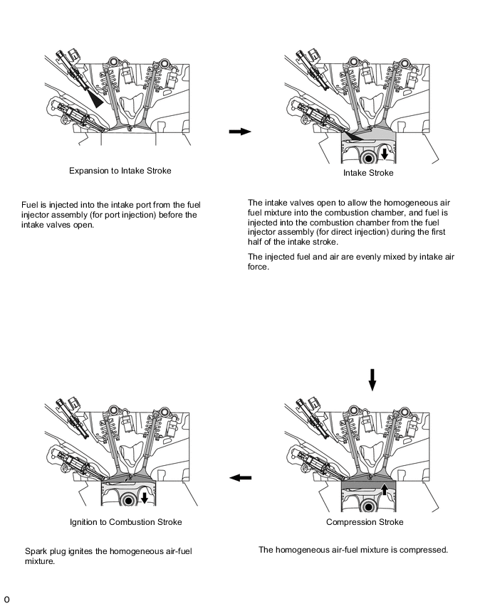
Homogeneous Combustion: To optimize combustion conditions, the ECM controls injection volume and timing of the fuel injector assemblies (for port injection) which inject fuel into the intake ports during the expansion, exhaust, and intake strokes. The ECM also controls the injection volume and timing of the fuel injector assemblies (for direct injection) which inject fuel during the first half of the intake stroke. The homogeneous air-fuel mixture is created by either combined or individual use of the 2 different types of injectors. This allows utilization of the evaporation heat of the injected fuel to cool the compressed air, and it also allows an increase of charging efficiency and power output.
-
-
Dual VVT-i System
-
The Dual Variable Valve Timing-intelligent (VVT-i) system is designed to control the intake and exhaust camshaft within a range of 57° and 32° respectively (of crankshaft angle) to provide valve timing that is optimally suited to the engine operating conditions on this Atkinson cycle engine. This improves torque in all the speed ranges as well as increasing fuel economy, and reducing exhaust emissions.
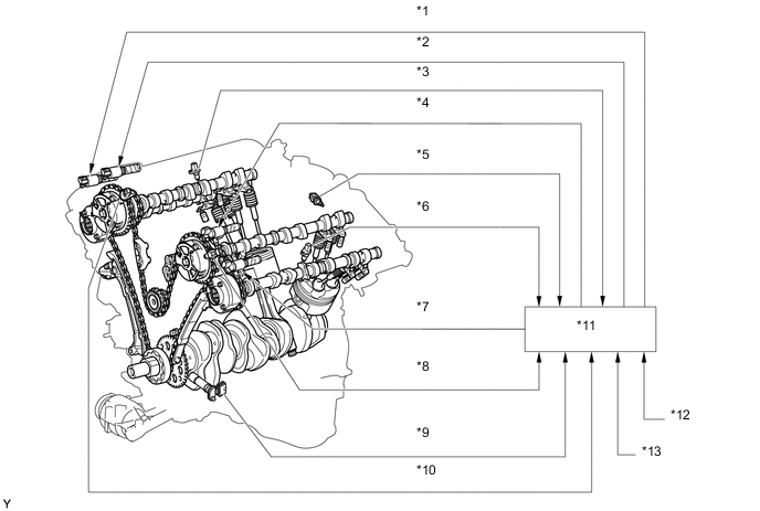
Text in Illustration *1 Camshaft Timing Oil Control Valve Assembly (Exhaust RH) *2 Camshaft Timing Oil Control Valve Assembly (Intake RH) *3 Camshaft Position Sensor (Exhaust RH) *4 Camshaft Timing Oil Control Valve Assembly (Intake LH) *5 Engine Coolant Temperature Sensor *6 Camshaft Position Sensor (Exhaust LH) *7 Camshaft Timing Oil Control Valve Assembly (Exhaust LH) *8 Camshaft Position Sensor (Intake LH) *9 Crankshaft Position Sensor *10 Camshaft Position Sensor (Intake RH) *11 ECM *12 Intake Mass Air Flow Meter Sub-assembly *13 Throttle Position Sensor - - 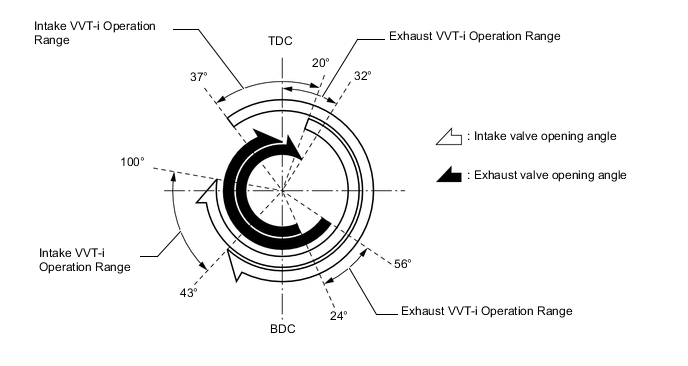
-
The Dual VVT-i system delivers excellent benefits in the different vehicle states as shown in the table below:
-
Upon Starting
-
Stopping Engine

*1 TDC *2 Earliest Timing (EX) *3 Latest Timing (IN) *4 BDC Objective Effect Controlling and fixing valve timing achieves the optimal timing for engine start. Improved startability -
During Idling

*1 TDC *2 Earliest Timing (EX) *3 Neutral Position (IN) *4 BDC Objective Effect Eliminating overlap reduces blow back to the intake side.
-
Stabilized idling speed
-
Better fuel economy
-
-
Low Speed Range with Light to Medium Load

*1 TDC *2 To Retard Side (IN) *3 To Retard Side (EX) *4 BDC Objective Effect Increasing overlap increases internal EGR reduces pumping losses.
Retarding the intake valve closing timing reduces pumping losses.
-
Better fuel economy
-
Improved emission control
-
-
In Low to Medium Speed Range with Heavy Load

*1 TDC *2 To Advance Side (EX) *3 To Advance Side (IN) *4 BDC Objective Effect Advancing the intake valve close timing reduces intake air blow back to the intake side and improves volumetric efficiency. Improved torque in low to medium speed ranges -
In High Speed Range with Heavy Load

*1 TDC *2 To Retard Side (IN) *3 To Advance Side (EX) *4 BDC Objective Effect Retarding the intake valve close timing improves volumetric efficiency using the inertia force of the intake air. Improved output
-
-
-
Electronic Throttle Control System-intelligent (ETCS-i)
-
The ETCS-i is used, providing excellent throttle control in all the operating ranges.
-
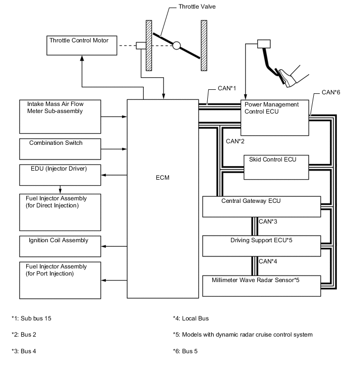
In the ETCS-i system, the power management control ECU calculates an optimal throttle valve opening angle that suits the driving conditions. The ECM controls the throttle control motor in accordance with the signals received from the power management control ECU.
-
The ETCS-i controls the idle speed, Traction Control (TRC), Vehicle Stability Control (VSC) system, cruise control system and dynamic radar cruise control system*.
-
*: Models with dynamic radar cruise control system
-
-
In case of an abnormal condition, this system switches to the limp mode.
-
-
Fuel Pump Control
-
The fuel pump is controlled by the fuel pump control ECU based on signals from the ECM. The fuel pump control has a fuel cut control. The fuel cut control stops the fuel pump when any of the Supplemental Restraint System (SRS) airbags have deployed.
-
-
Cooling Fan Control
-
The cooling fan control system achieves an optimal fan speed in accordance with the engine coolant temperature, vehicle speed, engine speed, and air conditioning operating conditions.
-
-
-
CONSTRUCTION
-
Intake Mass Air Flow Meter Sub-assembly
-
The intake mass air flow meter sub-assembly, which is a slot-in type, allows a portion of the intake air to flow through the detection area. By directly measuring the mass and the flow rate of the intake air, the detection precision is improved and the intake air resistance is reduced.
-
This intake mass air flow meter sub-assembly has a built-in intake air temperature sensor.
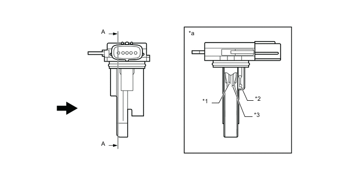
Text in Illustration *1 Platinum Hot-wire Element *2 Intake Air Temperature Sensor *3 Temperature Sensing Element - - *a A - A Cross Section - - 
Air Flow - -
-
-
Vacuum Sensor
-
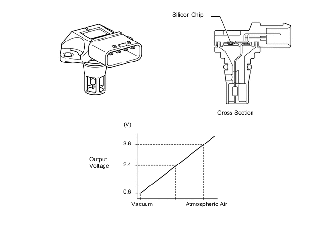
This sensor uses built-in semiconductors to detect the intake air surge tank pressure.
-
The vacuum sensor consists of a silicon chip which utilizes the characteristic of a silicon chip that changes its electrical resistance when pressure is applied to it. The sensor converts the pressure into an electrical signal and sends it to the ECM in an amplified form.
-
-
Crankshaft Position Sensor
-
A pick-up coil type crankshaft position sensor is used. The timing rotor of the crankshaft consists of 34 teeth, with 2 teeth missing. The crankshaft position sensor outputs the crankshaft rotation signals every 10°, and the missing teeth are used to determine the top dead center.
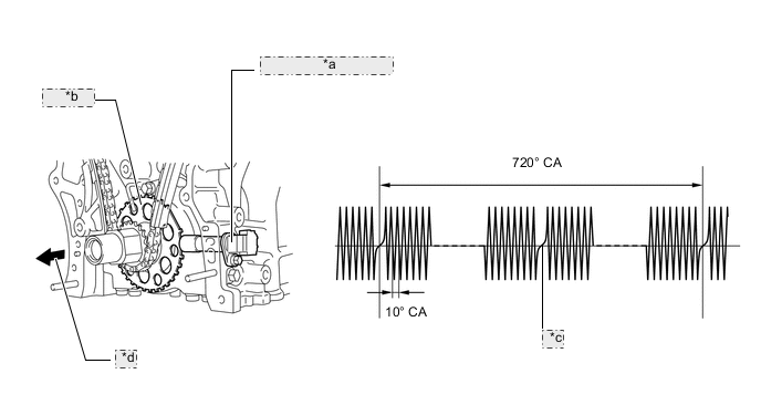
*a Crankshaft Position Sensor *b Timing Rotor *c 2 Teeth Missing *d Engine Front
-
-
Camshaft Position Sensor
-
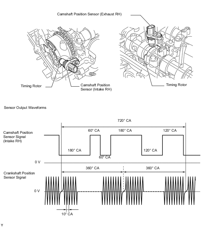
Magnetic Resistance Element (MRE) type camshaft position sensors (intake and exhaust) are used. To detect each camshaft (intake) position, a timing rotor that is secured to the camshaft (intake) in front of the camshaft timing gear assembly is used to generate 6 (3 high output, 3 low output) pulses for every 2 revolutions of the crankshaft. The timing rotor for each camshaft (exhaust) is part of the respective camshaft.
-
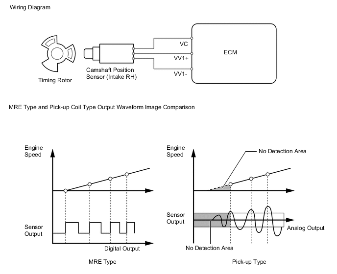
An MRE type camshaft position sensor consists of an MRE, a magnet and a sensor. The direction of the magnetic field changes due to the profile (protruding and non-protruding portions) of the timing rotor, which passes by the sensor. As a result, the resistance of the MRE changes, and the output voltage to the ECM changes to high or low. The ECM detects the camshaft position based on this output voltage.
-
-
Throttle Position Sensor
-
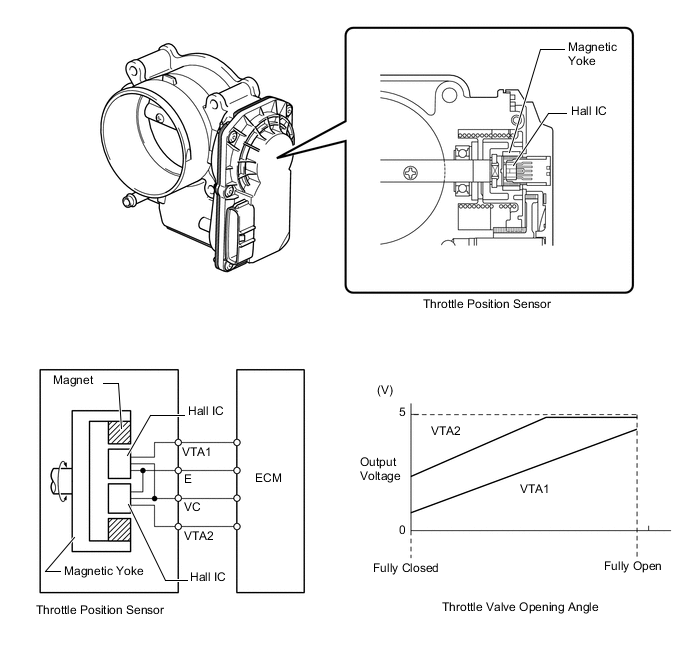
This non-contact type throttle position sensor uses a Hall IC, which is mounted on the throttle body.
-
The Hall IC is surrounded by a magnetic yoke. The Hall IC converts the changes that occur in the magnetic flux into electrical signals, and outputs them in the form of throttle valve position signals to the ECM.
-
The Hall IC contains circuits for the main and sub signals. The Hall IC converts the throttle valve opening angle into electric signals that have differing characteristics, and outputs them to the ECM.
-
-
Knock Control Sensor (Flat Type)
-
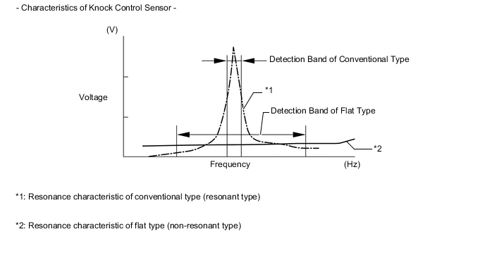
In a conventional type knock control sensor (resonant type), a vibration plate is built into the sensor. This plate has the same resonance point as the knocking* frequency of the engine block. This sensor can only detect vibration in this frequency band.
-
*: The term "knock" or "knocking" is used in this case to describe either preignition or detonation of the air fuel mixture in the combustion chamber. This preignition or detonation refers to the air fuel mixture being ignited earlier than is advantageous. This use of "knock" or "knocking" is not primarily used to refer to a loud mechanical noise that may be produced by an engine.
-
-
A flat type knock control sensor (non-resonant type) has the ability to detect vibration in a wider frequency band (from approximately 6 kHz to 15 kHz). The sensor has the following features:
-
The engine knocking frequency will vary slightly depending on the engine speed. The flat type knock control sensor can detect vibration even when the engine knocking frequency changes. Due to the use of the flat type knock control sensor, the vibration detection ability has been increased compared to a conventional type knock control sensor, and more precise ignition timing control is possible.
-
-
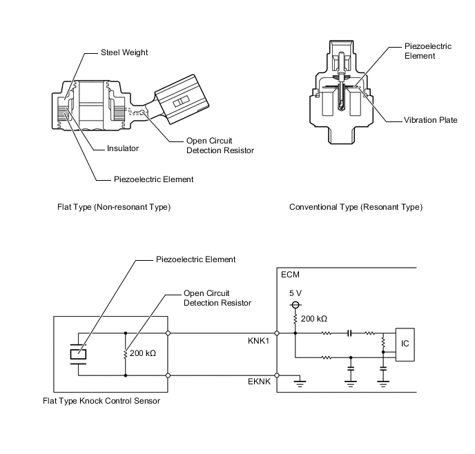
A flat type knock control sensor is installed on the cylinder block using the flange bolt. For this reason, a hole for the flange bolt exists in the center of the sensor.
-
In the sensor, a steel weight is located in the upper portion. An insulator is located between the weight and the piezoelectric element.
-
An open/short circuit detection resistor is integrated in the sensor. When the power switch is on (IG), the open/short circuit detection resistor in the knock control sensor and the resistor in the ECM keep the voltage at terminal KNK1 constant. An Integrated Circuit (IC) in the ECM constantly monitors the voltage of terminal KNK1. If the open/short circuit occurs between the knock control sensor and the ECM, the voltage of terminal KNK1 will change and the ECM will detect the open/short circuit and store a Diagnostic Trouble Code (DTC).
-
Vibrations caused by knocking are transmitted to the steel weight. The inertia of this weight applies pressure to the piezoelectric element. This action generates electromotive force.
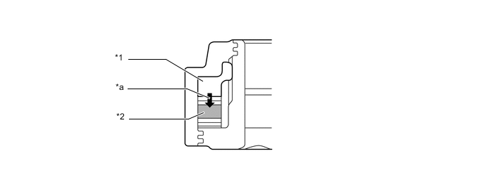
Text in Illustration *1 Steel Weight *2 Piezoelectric Element *a Inertia - - -
These knock control sensors are mounted in the specific directions and angles. To prevent the right and left bank connectors from being interchanged, make sure to install each sensor in its prescribed direction. For details, refer to the Repair Manual.
-
-
Air Fuel Ratio Sensor and Oxygen Sensor
-
A planar type air fuel ratio sensor and a cup type oxygen sensor are used. The basic construction of the oxygen sensor and the air fuel ratio sensor is the same. However, they are divided into the cup type and the planar type in accordance with the different types of heater construction used.
-
The planar type air fuel ratio sensor uses alumina, which excels in heat conductivity and electrical insulation, to integrate the sensor element with a heater, thus improving the warmup performance of the sensor.
-
The cup type oxygen sensor contains a sensor element that surrounds the heater.
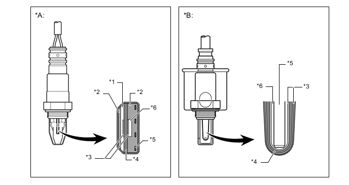
Text in Illustration *A Planar Type Air Fuel Ratio Sensor *B Cup Type Oxygen Sensor *1 Diffusion Resistance Layer *2 Alumina *3 Platinum Electrode *4 Sensor Element (Zirconia) *5 Heater *6 Atmosphere -
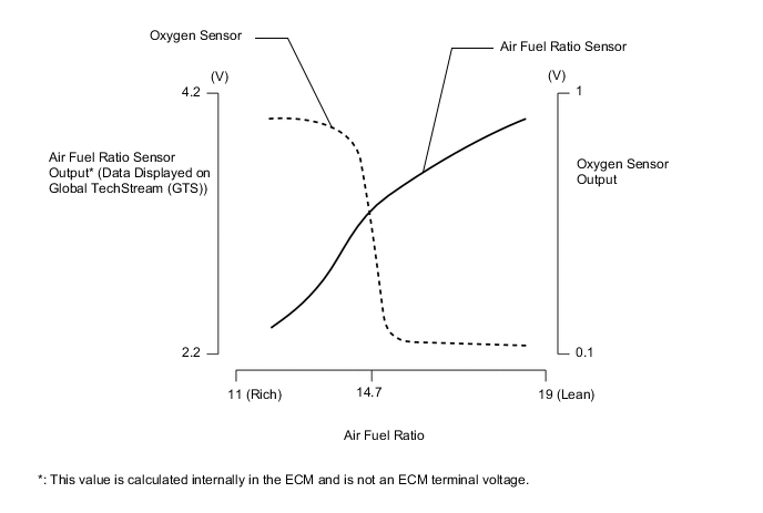
As illustrated below, the conventional oxygen sensor is characterized by a sudden change in its output voltage at the threshold of the stoichiometric air fuel ratio (14.7:1). In contrast, the air fuel ratio sensor data is approximately proportionate to the existing air fuel ratio. The air fuel ratio sensor converts the oxygen density to current and sends it to the ECM. As a result, the detection precision of the air fuel ratio has been improved. The air fuel ratio sensor data can be viewed using a Global TechStream (GTS).
-
-
Camshaft Timing Oil Control Valve Assembly
-
This camshaft timing oil control valve assembly controls the spool valve using duty-cycle control from the ECM. This allows hydraulic pressure to be applied to the camshaft timing gear assembly or camshaft timing exhaust gear assembly advance or retard side. When the engine is stopped, the camshaft timing oil control valve assembly (intake) will move to the retard position, and the camshaft timing oil control valve assembly (exhaust) will move to the advance position.
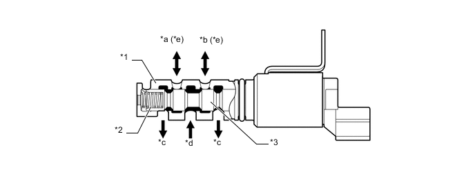
Text in Illustration *1 Sleeve *2 Spring *3 Spool Valve - - *a To Camshaft Timing Gear Assembly (Advance Side) *b To Camshaft Timing Gear Assembly (Retard Side) *c Drain *d Oil Pressure *e On the camshaft timing oil control valve (exhaust), the advance and retard sides are reversed. - -
-
-
Ignition Coil Assembly
-
The Direct Ignition System (DIS) provides 6 ignition coil assemblies, one for each cylinder. The spark plug caps, which provide contact to spark plugs, are integrated with the ignition coil assembly. Also, an igniter is enclosed to simplify the system.
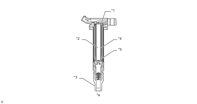
Text in Illustration *1 Igniter *2 Iron Core *3 Plug Cap *4 Secondary Coil *5 Primary Coil - - *a Cross Section - -
-
-
Spark Plug
-
Long-reach type spark plugs are used. This type of spark plugs allows the area of the cylinder head sub-assembly that receives the spark plugs to be made thick. Thus, the water jacket can be extended near the combustion chamber, which contributes to cooling performance.
-
The triple ground electrode type iridium-tipped spark plugs are used to achieve a 100000 km (60000 miles) maintenance interval. By making the center electrode of iridium, it is possible to achieve superior ignition performance and durability when compared to platinum-tipped spark plugs. Furthermore, two ground electrodes have been added to further enhance ignitability, wear resistance, and fouling resistance.
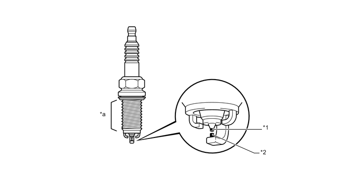
Text in Illustration *1 Iridium Tip *2 Platinum Tip *a Long-reach - -
-
-
-
OPERATION
-
Dual VVT-i System
-
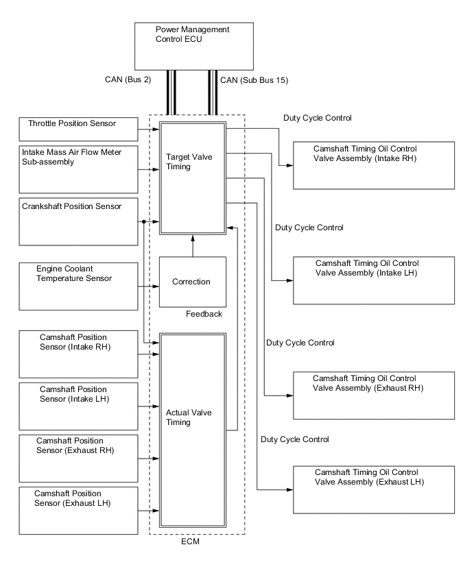
Based on engine speed, intake air mass, throttle position and engine coolant temperature, the ECM calculates optimal valve timing for all driving conditions. The ECM also controls the camshaft timing oil control valve assemblies. In addition, the ECM uses signals from the camshaft position sensors and the crankshaft position sensor to detect the actual valve timing, thus providing feedback control to achieve the target valve timing.
-
When the camshaft timing oil control valve assembly is positioned as illustrated below by the advance signals from the ECM, the resultant oil pressure is applied to the timing advance side vane chamber to rotate the camshaft in the timing advance direction:
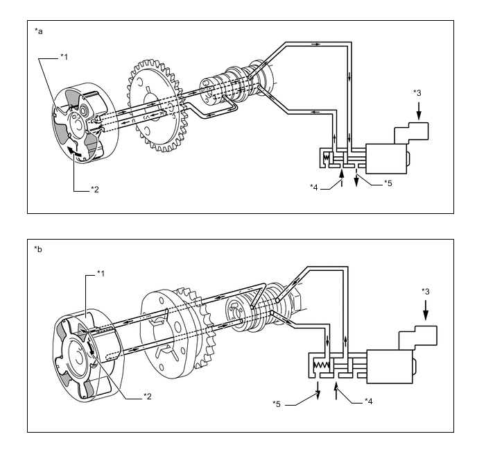
Text in Illustration *1 Vane *2 Rotation Direction *3 ECM *4 In (Oil Pressure) *5 Drain (Oil Pressure) - - *a Advance Side Operation Intake Side *b Advance Side Operation Exhaust Side -
When the camshaft timing oil control valve assembly is positioned as illustrated below by the retard signals from the ECM, the resultant oil pressure is applied to the timing retard side vane chamber to rotate the camshaft in the timing retard direction:
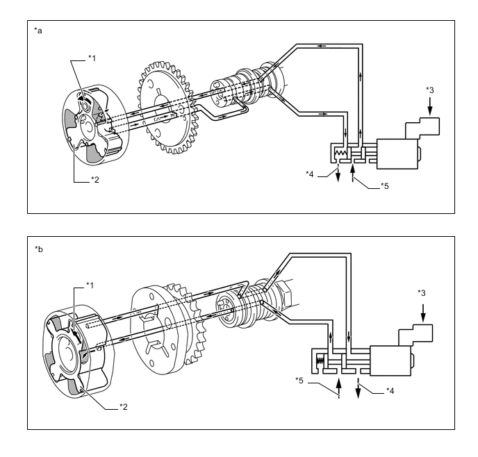
Text in Illustration *1 Rotation Direction *2 Vane *3 ECM *4 Drain (Oil Pressure) *5 In (Oil Pressure) - - *a Retard Side Operation Intake Side *b Retard Side Operation Exhaust Side -
After reaching the target timing, the engine valve timing is maintained by keeping the camshaft timing oil control valve assembly in the neutral position unless the engine operating conditions change. This maintains the engine valve timing at the desired target position by preventing the engine oil from running out of the camshaft timing oil control valve assembly.
-
-
Fuel Pump Control
-
In this vehicle, there are 2 types of fuel pump controls. The fuel pump is controlled to an optimum speed to match the engine operating conditions, and the fuel pump operation is stopped when the SRS airbags deploy.
-
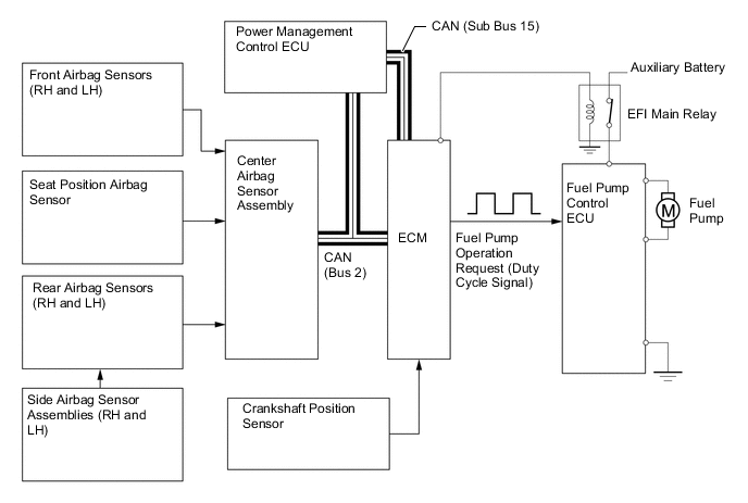
The ECM transmits a fuel pump operation request signal to the fuel pump control ECU that corresponds to the engine operating conditions. The fuel pump control ECU receives this request signal and controls the speed of the fuel pump. As a result, under light engine loads, fuel pump speed is kept low to reduce electric power loss.
-
A fuel cut control is used to stop the fuel pump when any of the SRS airbags deploys. In this control, if an airbag deployment signal from the center airbag sensor assembly is detected by the ECM, the ECM will turn off the circuit opening relay. As a result, the power supply to the fuel pump control ECU is stopped, causing the fuel pump to stop operating. After the fuel cut control has been activated, turning the power switch from off to on (IG) cancels the fuel cut control, and the engine can be restarted.
-
The fuel pump control ECU controls fuel pump speed by receiving a duty cycle signal (FPC terminal input) from the ECM.
-
-
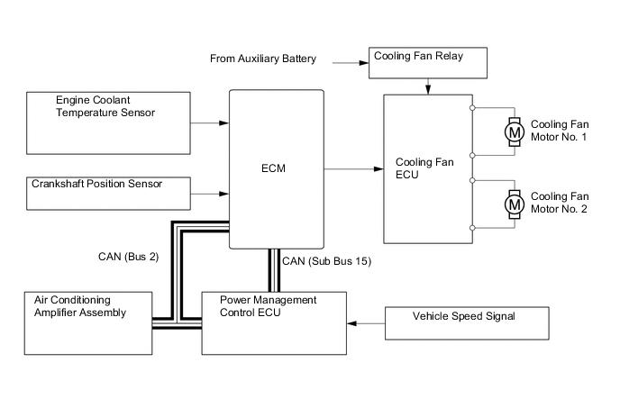
Cooling Fan Control
-
The ECM calculates the cooling fan speed in accordance with the engine coolant temperature, vehicle speed, engine speed and air conditioning operating conditions, and sends the signals to the cooling fan ECU. Upon receiving the signals from the ECM, the cooling fan ECU actuates the cooling fan motor.
-
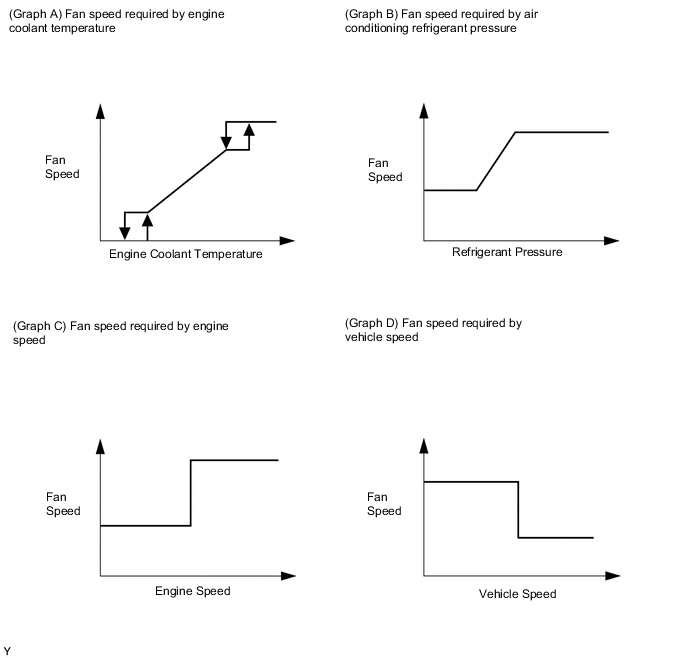
As illustrated below, the ECM determines the required fan speed by selecting the fastest fan speed from among the following:
-
The graphs below show the fan speed required by the engine coolant temperature (Graph A), the fan speed required by the air conditioning refrigerant pressure (Graph B), the fan speed required by the engine speed (Graph C), and the fan speed required by the vehicle speed (Graph D).
-
-
ETCS-i
-
The ECM drives the throttle control motor by determining the target throttle valve opening in accordance with the respective operating condition.
-
The ECM controls the throttle valve in order to constantly maintain an ideal idle speed.
-
As part of the TRC, the throttle valve opening angle is reduced by a demand signal sent from the skid control ECU to the ECM. This demand signal is sent if an excessive amount of slippage occurs at a drive wheel, thus ensuring vehicle stability and applying an appropriate amount of power to the road.
-
In order to bring the effectiveness of the VSC into full play, the throttle valve angle is regulated through a coordination control by the skid control ECU and the ECM.
-
In situations in which low-μ (low friction coefficient) road surface conditions can be anticipated, such as when driving in the snow, the rate of throttle valve opening can be controlled to help vehicle stability while driving on the slippery surface. This is accomplished by turning on SNOW mode. Pressing the SNOW side of the combination switch activates this mode. This mode modifies the relationship and reaction of the throttle to the accelerator pedal, and assists the driver by reducing the engine output from that of a normal level.
-
The ECM directly actuates the throttle valve for operation of the cruise control.
-
On the models with dynamic radar cruise control system, the dynamic radar cruise control uses a millimeter wave radar sensor and driving support ECU to determine the distance, direction, and relative speed of a vehicle ahead. Thus, the system can effect deceleration control, follow-up control, constant speed control, and acceleration control. To make these controls possible, the ECM controls the throttle valve.
-
-