LIGHTING SYSTEM
-
FUNCTION OF MAIN COMPONENTS
-
Daytime Running Light System
Component Function Main Body ECU (Driver Side Junction Block)
-
The main body ECU receives the signals from the headlight dimmer switch assembly.
-
The main body ECU transmits the signals to the combination meter assembly and the front controller.
Headlight Dimmer Switch Assembly The headlight dimmer switch assembly transmits the light control switch position signal to the main body ECU. Front controller (Multiplex Network Front Light ECU) The front controller preforms the daytime running lights based on request signals that are received from the main body ECU. Hybrid Vehicle Control ECU The hybrid vehicle control ECU sends a vehicle information signal via the CAN communication. Headlight Assembly Daytime Running Light The Light Emitting Diode (LED) light illuminates. LED Driver Module (for Daytime Running Light/Clearance Light) The LED driver module keeps a constant level of direct current applied to the LED, achieving stable LED illumination. -
-
Automatic Beam Level Control System
Component Function Headlight Swivel ECU Assembly*1 or AHS ECU*2
-
Calculates changes in the vehicle posture based on the signals from the height control sensor or air suspension control ECU and the vehicle speed signal.
-
Outputs the control signal to the headlight swivel motor assembly.
-
Provides initial set control, fail-safe function and diagnosis function.
Headlight Assembly Headlight Swivel Motor Based on the signals received from the headlight swivel ECU assembly or AHS ECU, the actuators move the reflectors in the headlights. Height Control Sensor (Front and Rear) Detects the height of the vehicle. Skid Control ECU Assembly Transmits the speed sensor signal (front LH and RH) to the headlight swivel ECU assembly or AHS ECU. Hybrid Vehicle Control ECU Transmits the READY status signal. Main Body ECU (Driver Side Junction Block) Transmits the headlight status signal. Suspension Control ECU Transmits the height of the vehicle detected by the height control sensor to the headlight swivel ECU assembly. Combination Meter Assembly Multi-information Display When the system malfunctions, the meter ECU illuminates the master warning light based on the signal from the headlight swivel ECU assembly or AHS ECU and indicates the warning message on the multi-information display to alert the driver.
-
*1: Models without Adaptive High-beam System (AHS)
-
*2: Models with Adaptive High-beam System (AHS)
-
-
Intelligent Adaptive Front-lighting System (AFS)
Component Function Headlight Swivel ECU Assembly*1 or AHS ECU*2
-
Receives various signals, calculates the target lighting angle and actuates the headlight swivel actuator.
-
Outputs the control signal to the headlight swivel motor assembly.
-
Provides initial set control, fail-safe function and diagnosis function.
Headlight Assembly Headlight Swivel Motor Driven by the headlight swivel ECU assembly or AHS ECU, the actuator moves the lo beam left or right to the angle calculated by the headlight swivel ECU assembly or AHS ECU. Steering Sensor Detects the steering angle and direction and outputs this signal to the headlight swivel ECU assembly. Skid Control ECU Assembly Transmits the speed sensor signal (Front LH and RH) to the headlight swivel ECU assembly or AHS ECU. Hybrid Vehicle Control ECU
-
Transmits the READY status signal.
-
Transmits the shift position signal to the headlight swivel ECU assembly or AHS ECU. The headlight swivel ECU assembly or AHS ECU determines whether the vehicle is moving forward or backward from this signal.
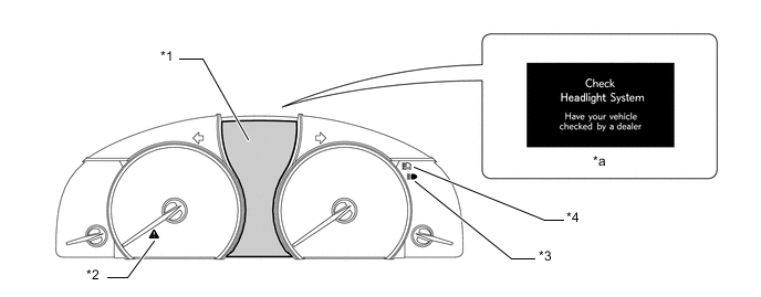
Main Body ECU (Driver Side Junction Block) Transmits the headlight status signal. Suspension Control ECU Transmits the height of the vehicle detected by the height control sensor to the headlight swivel ECU assembly. Combination Meter Assembly Multi-information Display The multi-information display shows "Check Headlight System" via signals from the headlight swivel ECU assembly during a system malfunction.
-
*1: Models without Adaptive High-beam System (AHS)
-
*2: Models with Adaptive High-beam System (AHS)
-
-
Automatic High Beam (AHB) System
Component Function Automatic High Beam Sensor (Inner Rear View Mirror Assembly) The automatic high beam sensor determines when to turn the hi beams on and off after identifying the lights of oncoming vehicles, preceding vehicles and other lights from the picture information of its camera sensor. Then, the sensor sends hi beam request signals to the headlight swivel ECU assembly via Local Interconnect Network (LIN). Headlight Swivel ECU Assembly The headlight swivel ECU assembly acts as the gateway between Local Interconnect Network (LIN) and Controller Area Network (CAN). Main Body ECU (Driver Side Junction Block)
-
The main body ECU receives the signals from the headlight dimmer switch assembly and the automatic light control sensor.
-
The main body ECU transmits the signals to the combination meter assembly and the front controller.
Skid Control ECU Assembly The skid control ECU assembly outputs information about the speed of the front right wheel. This information is used by the automatic high beam sensor to control switching between the high and lo beams of the Automatic High Beam (AHB) system. Hybrid Vehicle Control ECU
-
The hybrid vehicle control ECU outputs a signal to indicate that the shift lever is in R. Based on this signal, the automatic high beam sensor determines the direction of vehicle movement.
-
The ECM sends a vehicle information signal via the CAN communication.
Headlight Dimmer Switch Assembly The headlight dimmer switch assembly transmits the auto position signal and the hi beam position signal to the main body ECU. Steering Sensor The steering sensor outputs the steering angle. Combination Meter Assembly Automatic High Beam Indicator Light The automatic high beam indicator light illuminates to inform the driver when the Automatic High Beam (AHB) system is activated. Headlight High Beam Indicator Light The headlight high beam indicator light illuminates to inform the driver when the hi beam headlights are on. Multi-information Display The multi-information display shows "Check Headlight System" via signals from the headlight swivel ECU assembly during a system malfunction. Front Controller (Multiplex Network Front Light ECU) The front controller controls the hi beams based on request signals that are received from the main body ECU. Automatic Light Control Sensor The automatic light control sensor detects the ambient light level and transmits it to the main body ECU. Driver Side Module Switch (Automatic High Beam Switch) The driver side module switch (automatic high beam switch) outputs an automatic high beam switch operation signal to the main body ECU. Headlight Assembly LO/HI Switching Motor The LO/HI switching motor switches between lo beam and hi beam through the control of the front controller EDU, which receives signals from the main body ECU. -
-
Adaptive High-beam System (AHS)
Component Function Adaptive High-beam Sensor (Inner Rear View Mirror Assembly) The adaptive high-beam sensor identifies the lights of oncoming vehicles, preceding vehicles and other lights from the picture information of its camera sensor. Then, the sensor sends signals to the AHS ECU via the CAN network. AHS ECU
-
The AHS ECU receives the signals from adaptive high-beam sensor and other ECUs.
-
The AHS ECU determines when to turn the hi beams or half shade beams on or off. Then the AHS ECU sends these signals to the headlight swivel actuator and AHS EDU.
Main Body ECU (Driver Side Junction Block)
-
The main body ECU receives the signals from the headlight dimmer switch assembly and the automatic light control sensor.
-
The main body ECU transmits the signals to the combination meter assembly and the front controller.
Skid Control ECU Assembly The skid control ECU assembly outputs information about the speed of the front right wheel. This information is used by the AHS ECU to control Adaptive High-beam System (AHS). Headlight Dimmer Switch Assembly The headlight dimmer switch assembly transmits the auto position signal and the hi beam position signal to the main body ECU. Steering Sensor The steering sensor outputs the steering angle. Combination Meter Assembly Adaptive High-beam Indicator Light
-
The adaptive high-beam indicator light illuminates to inform the driver when the Adaptive High-beam System (AHS) is activated.
-
The adaptive high-beam indicator light flashes to inform the driver when a malfunction is detected in this system.
Headlight High Beam Indicator Light The headlight high beam indicator light illuminates to inform the driver when the hi beam and half shade beam headlights are on. Multi-information Display The multi-information display shows "Headlight System Check" via signals from the AHS ECU during a system malfunction. Front Controller (Multiplex Network Front Light ECU) The front controller performs the hi beams based on request signals that are received from the main body ECU and AHS ECU. Automatic Light Control Sensor The automatic light control sensor detects the ambient light level and transmits it to the main body ECU. AHS EDU The AHS EDU operates the half shade motor and the LO/HI switching motor in response to LIN communication signals from the AHS ECU. Driver Side Module Switch (AHS Switch) The driver side module switch (AHS switch) outputs an AHS switch operation signal to the AHS ECU. Yawrate Sensor The yawrate sensor sends a yaw rate signal via CAN communication. Hybrid Vehicle Control ECU
-
The hybrid vehicle control ECU sends a vehicle information signal via CAN communication.
-
The hybrid vehicle control ECU outputs a signal to indicate that the shift lever is in R. Based on this signal, the adaptive high beam sensor determines the direction of vehicle movement.
Headlight Assembly Half Shade Motor The half shade motor switches between hi beam and half shade beam through the control of the AHS EDU, which receives signals from the AHS ECU. LO/HI Switching Motor The LO/HI switching motor switches between lo beam and hi beam through the control of the AHS EDU, which receives signals from the AHS ECU. Headlight Swivel Motor Assembly The headlight swivel motor assembly controls the horizontal light beam axis of the headlight through AHS ECU control. -
-
Illumination System
Component Function Certification ECU (Smart Key ECU Assembly) The certification ECU judges and certifies the ID code. Main Body ECU (Driver Side Junction Block) The main body ECU receives various signals and transmits the signals to the front controller and rear J/B ECU. Front Controller (Multiplex Network Front Light ECU) The front controller performs the clearance lights based on request signals that are received from the main body ECU. Rear J/B ECU (Luggage Room Junction Block Assembly) The rear J/B ECU performs the clearance lights based on request signals that are received from the main body ECU. Headlight Assembly (RH, LH) Clearance Lights The Light Emitting Diode (LED) light illuminates. Rear Combination Light Assembly (RH, LH) Taillights The Light Emitting Diode (LED) light illuminates. Rear Light Assembly (RH, LH) Automatic Light Control Sensor The automatic light control sensor detects the ambient light level and transmits it to the main body ECU.
-
-
OPERATING CONDITION
-
Daytime Running Light System
-
The daytime running lights illuminate when the following conditions are met:
-
The power switch is on.
-
The READY signal is input.
-
The light control switch off, TAIL or AUTO (if headlight-on control is not being performed by the automatic light control).
-
The parking brake release signal.
-
-
-
Light Auto Turn-off System
-
The light auto turn-off system turns all exterior lights off approximately 30 seconds after either of the following conditions is met:
-
The power switch is turned off, any door is opened and all the doors and luggage compartment door are closed with all exterior lights on.
-
The power switch is turned off, all the doors are closed and the luggage compartment door is opened and closed with all exterior lights on.
-
-
This system turns all exterior lights off immediately when the lock button on the wireless remote control is pushed with all the doors are locked.
-
When the power switch is turned off and the driver's door is opened with the exterior lights except headlights on, this system turns them off.
-
-
Intelligent Adaptive Front-lighting System (AFS)
-
The intelligent AFS (low speed control) will operate when all of the following conditions are met:
-
Power switch on (Ready)
-
Vehicle is moving forward at a speed of 10 km/h (6 mph) or more.
-
Steering angle is 6° or more.
-
Headlight lo beam is operating (except when the daytime running light system is operating).
-
-
During the low speed control, the headlight swivel ECU assembly or AHS ECU calculates the swivel angle from the steering angle and drives the headlight swivel actuator on the side facing into the turn to illuminate the road ahead during cornering.
Swivel Angle Range Driving Condition Headlight Assembly Left Left Right Right Turn 0° Fixed 0° to 10° to Right Left Turn 0° to 20° to Left 0° Fixed -
The intelligent AFS (medium-to-high speed control) operates when all of the following conditions are met:
-
Power switch on (Ready)
-
Vehicle is moving forward at a speed of 30 km/h (19 mph) or more.
-
Steering angle is 7.5° or more.
-
Headlight lo beam is operating (except when the daytime running light system is operating).
-
-
During the medium-to-high speed control, based on the steering angle and vehicle speed, the headlight swivel ECU assembly or AHS ECU calculates the swivel angle of the lo beam headlights, so that the headlights can illuminate the position which the vehicle will reach after 3 seconds, and drives both headlight swivel actuators to illuminate the road ahead during cornering.
Swivel Angle Range Driving Condition Headlight Assembly Left Left Right Right Turn 0° to 5° to Right 0° to 10° to Right Left Turn 0° to 15° to Left 0° to 7.5° to Left
-
-
Automatic High Beam (AHB) System
-
The Automatic High Beam (AHB) system operate as follows:
Condition Details System Activation When all of the following conditions are met, the Automatic High Beam (AHB) system is activated and the automatic high beam indicator light turns on:
-
The power switch is on (IG).
-
The headlight dimmer switch assembly is in the AUTO position or HEAD position and high beam position.
-
The automatic light control sensor outputs the night mode signal to turn the headlights on.
Hi Beam Headlight On When all of the following conditions are met, the Automatic High Beam (AHB) system turns on the hi beam headlights after a short delay:
-
Vehicle speed is more than approximately 30 to 40 km/h (19 to 25 mph).
-
The area in front of the vehicle is dark.
-
No oncoming vehicles are present with the headlights on.
-
No preceding vehicles are present with the taillights on.
-
Few streetlights are present along the street ahead.
Hi Beam Headlight Off (Lo Beam Headlight On) When any of the following conditions are met, the automatic system turns off the hi beam headlights after a short delay:
-
Vehicle speed is less than approximately 25 to 30 km/h (16 to 19 mph).
-
The area in front of the vehicle is not dark.
-
An oncoming vehicle with headlights on is detected.
-
A preceding vehicle with taillights on is detected.
-
Several streetlights are present along the street ahead.
-
-
-
Adaptive High-beam System (AHS)
-
The Adaptive High-beam System (AHS) operates as follows:
Condition Details System Activation When all of the following conditions are met, the Adaptive High-beam System (AHS) is activated and the adaptive high beam indicator light turns on:
-
The power switch is on (IG).
-
The headlight dimmer switch assembly is in the AUTO position or HEAD position and hi beam position.
-
The automatic light control sensor outputs the night mode signal.
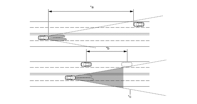
Hi Beam Headlight On When all of the following conditions are met, the Adaptive High-beam System (AHS) turns on the hi beam headlights after a short delay:
-
Vehicle speed is more than approximately 30 km/h (20 mph).
-
The area in front of the vehicle is dark.
-
Oncoming vehicles with the headlights on are not detected in area A and area B in the illustration.
-
Preceding vehicles with the taillights on are not detected in area A and area B in the illustration.
-
Few streetlights are present along the street ahead.
Hi Beam Headlight Off (Lo Beam Headlight On) When any of the following conditions are met, the automatic system turns off the hi beam headlights after a short delay:
-
Vehicle speed is less than approximately 25 km/h (16 mph).
-
The area in front of the vehicle is not dark.
-
An oncoming vehicle with the headlights on is detected in area B in the illustration.
-
A preceding vehicle with the taillights on is detected in area B in the illustration.
-
Several streetlights are present along the street ahead.
Variable Shade Beam On When all of the following conditions are met, the variable shade beam turns on after a short delay:
-
Vehicle speed is less than approximately 30 km/h (20 mph).
-
The area in front of the vehicle is dark.
-
An oncoming vehicle with the headlights on can be detected only in area A in the illustration.
-
A preceding vehicle with the taillights on can be detected only in area A in the illustration.
-
Several streetlights are present along the street ahead.
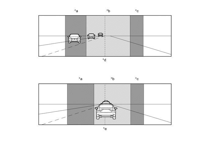
Text in Illustration *a Detection Area B (Left Side) *b Detection Area A *c Detection Area B (Right Side) *d Detection for Oncoming Vehicle *e Detection for Preceding Vehicle - - -
-
-
Illumination System
-
The Illumination system operates as follows:
Condition Details Door Unlock-linked When all of the following conditions are met, the clearance lights and taillight automatically turn on:
-
The engine switch is off.
-
Any door is unlocked.
-
All doors are closed.
-
The ambient light level is dark.
Door Lock-linked When one of the following conditions is met, the clearance lights and taillight automatically turn off:
-
All doors are locked.
-
All doors are closed.
-
-
-
Emergency Brake Signal
-
The activating and deactivating conditions for the emergency brake signal are as shown in the following table:
Condition Details Emergency Brake Signal Operating Conditions When all of the following conditions are met, the emergency brake signal starts operating:
-
The vehicle speed is above 55 km/h (35 mph).
-
The driver is depressing the brake pedal.
-
Emergency braking is detected from the vehicle deceleration.
Emergency Brake Signal Ending Conditions When any of the following conditions is met, the emergency brake signal stops operating:
-
The driver has released the brake pedal.
-
Emergency braking is no longer detected from the vehicle deceleration.
-
The driver has pressed the hazard warning signal switch.
-
-
-
Light Auto Turn-off System (Follow Me Home Function)
-
The light auto turn-off system operates as follows:
Condition Details Follow Me Home When approx. 30 seconds elapse after all of the following conditions are met, the head lights turn off:
-
The power switch is off.
-
All doors are closed.
-
The headlight dimmer switch assembly is in the pass position, then neutral position.
-
-
-
-
SYSTEM CONTROL
-
Intelligent Adaptive Front-lighting System (AFS)
-
The headlight swivel ECU assembly calculates the target lighting angle of the lo beam by receiving the steering angle and the vehicle speed. Then, the AFS ECU actuates the headlight swivel actuator in order to attain the target lighting angle.
-
The operation angle of the headlights is detected through the position (number of steps) of the step motor in the headlight swivel actuator.
-
The swivel angle control is switched between the medium-to-high speed and the low speed controls in accordance with the steering angle and vehicle speed.
-
Initial Set Control
-
When the hybrid system is READY, the headlight swivel ECU assembly drives the headlight swivel actuator, moves the projector headlight to the operation limit in the direction toward the vehicle center and returns it to the proper position. The headlight swivel ECU assembly assesses the position of the headlight for reference control.
-
-
-
Adaptive High-beam System (AHS)
-
The Adaptive High-beam System (AHS) operates the LO/HI switching shade via the LO/HI switching motor when the lo beam illumination conditions are met, and turns the lo beam headlights on.
-
The Adaptive High-beam System (AHS) operates the LO/HI switching shade via the LO/HI switching motor when the hi beam illumination conditions are met, and turns the hi beam headlights on.
-
When the conditions of the variable shade beam illumination are met, the Adaptive High-beam System (AHS) turns the LO/HI switching shade to hi beam using the LO/HI switching motor and operates the half shade beam shade via the half shade beam motor to partially block the inner side of the vehicle hi beam. In this situation, the illumination area can be changed by driving the headlight swivel motor in response to the taillights of a preceding vehicle or the headlight position of an oncoming vehicle which is detected by the adaptive high beam sensor.
-
When Preceding Vehicle or Oncoming Vehicle is Approaching
-
The AHS ECU moves the variable shade beam outward when the vehicle is approaching the taillights of a preceding vehicle or when the headlights of an oncoming vehicle are approaching.
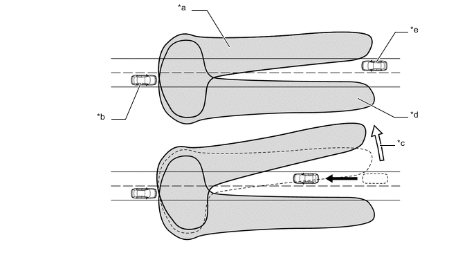
Text in Illustration *a Lighting Area (Left Side Headlight) *b Own Vehicle *c Outward *d Lighting Area (Right Side Headlight) *e Oncoming Vehicle - - -
-
When Preceding Vehicle or Oncoming Vehicle is Moving Away
-
The AHS ECU moves the variable shade beam inward when the vehicle is moving away from the taillights of a preceding vehicle or when the headlights of an oncoming vehicle are moving away.
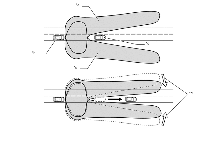
Text in Illustration *a Lighting Area (Left Side Headlight) *b Own Vehicle *c Lighting Area (Right Side Headlight) *d Preceding Vehicle *e Inward - - -
-
-
Lane Change Flasher System
-
The lane change flasher system operates in the following way:
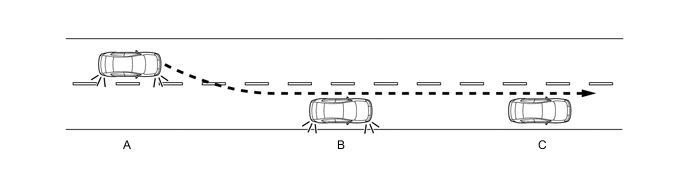
Condition Turn Signal Switch Turn Signal Light A Commencing lane changing Moves to the lane change position. Starts flashing B During lane changing Not moved.
-
If operation finishes during lane changing, flashing will start if the lane change position is moved to again.
Turns off after flashing 3 times* C Finishing lane changing Not moved.
-
If the turn signal light is flashing even after lane changing has finished, moving the switch in the direction opposite to the current position will extinguish the light.
Turns off Tech Tips
*: The flashing frequency can be configured by means of the customization function (customizable parameter: off, 3, 5, 7, 9 or 11). For details, refer to the Repair Manual.
-
-
-
-
FUNCTION
-
Automatic High Beam (AHB) System
-
When passing an oncoming vehicle
-
The Automatic High Beam (AHB) system turns the hi beam headlights off when there is an oncoming vehicle and the distance reaches approximately 800 m (2625 ft.).
-
When an oncoming vehicle passes the automatic high beam sensor range, the Automatic High Beam (AHB) system turns the hi beam headlights on after a short delay.
Text in Illustration *a Approx. 800 m (2625 ft.) *b Delay *c Camera Angle - - -
-
When passing a preceding vehicle
-
The Automatic High Beam (AHB) system turns the hi beam headlights off when there is a preceding vehicle and the distance reaches approximately 600 m (1969 ft.).
-
When a preceding vehicle passes the automatic high beam sensor range, the Automatic High Beam (AHB) system turns the hi beam headlights on after a short delay.
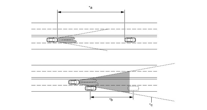
Text in Illustration *a Approx. 600 m (1969 ft.) *b Delay *c Camera Angle - - -
-
-
-
CONSTRUCTION
-
LED Headlight System
-
Projector Type LED Light
-
Through optimization of the shape of the lenses and reflectors inside the lights, a large illumination range has been acheived.
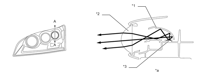
Text in Illustration *1 Reflector *2 Lens *3 LED - - *a A - A Cross Section - - -
-
Parabolic Type LED Light
-
The optimal reflector shape contributes to effective illumination without any loss of discharged light.
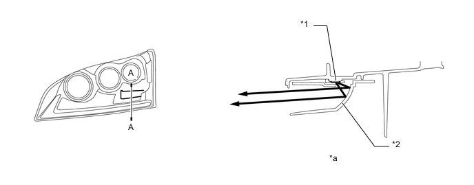
Text in Illustration *1 LED *2 Reflector *a A - A Cross Section - - -
-
LED Driver Module
-
When the headlights are turned on, the LED driver modules immediately turn on the LEDs (approximately 0.1 seconds). In addition, by regulating the output current flowing into the LEDs at a specified level, the LED driver modules prevent the light from getting brighter and dimmer due to voltage variation.
-
If malfunctions occur in an LED headlight system, the LED driver module transmits fail signals to the headlight swivel ECU or AHS ECU*2. When the headlight swivel ECU or AHS ECU*2 receives the fail signals, it transmits signals to the combination meter assembly to warn the driver.
-
*1: Models without Adaptive High-beam System (AHS)
-
*2: Models with Adaptive High-beam System (AHS)
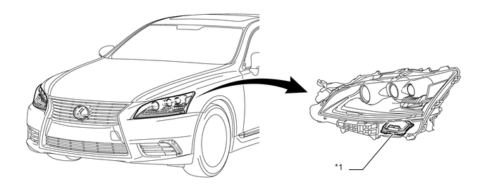
Text in Illustration *1 LED Driver Module (Light Control ECU) - - -
-
Combination Meter Assembly
-
If malfunctions occur in the LED headlight system, the combination meter assembly warns the driver by indicating a message on the multi-information display, sounding the buzzer and illuminates the master warning light when receiving signals from the headlight swivel ECU*1 or AHS ECU assembly*2.
-
*1: Models without Adaptive High-beam System (AHS)
-
*2: Models with Adaptive High-beam System (AHS)
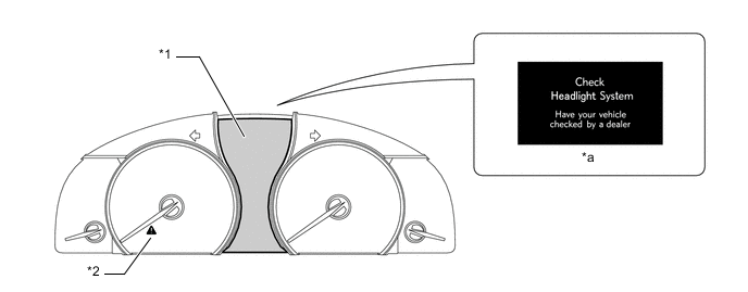
Text in Illustration *1 Multi-information Display *2 Master Warning Light *a Warning Message - - -
-
-
Automatic Headlight Beam Level Control System
-
When the headlights are on, the automatic headlight beam level control system operates the headlight swivel motor in accordance with the posture of the vehicle.
-
The automatic headlight beam level control system mainly consists of the headlight swivel ECU*1 or AHS ECU*2, front and rear height control sensor and 2 headlight swivel motors.
-
The headlight swivel ECU*1 or AHS ECU*2 calculates changes in the vehicle posture based on the signals from the air suspension ECU.
-
The headlight swivel ECU*1 or AHS ECU*2 then controls the headlight swivel motor based on this information in order to change the headlight angle.
-
Initial Set Control
-
When the hybrid system is READY, the headlight swivel ECU*1 or AHS ECU*2 drives the headlight level actuator, moves the headlight reflector to the lower limit position and returns it to the proper position. The headlight swivel ECU*1 or AHS ECU*2 assesses the position of the headlight for reference control.
-
*1: Models without Adaptive High-beam System (AHS)
-
*2: Models with Adaptive High-beam System (AHS)
-
-
-
Automatic High Beam (AHB) System
-
Automatic High Beam Sensor (Inner Rear View Mirror Assembly)
-
The automatic high beam sensor consists of a Complementary Metal Oxide Semiconductor (CMOS) that receives images and mirror portion that identifies light sources, and judges whether to turn hi beam headlights on or off.
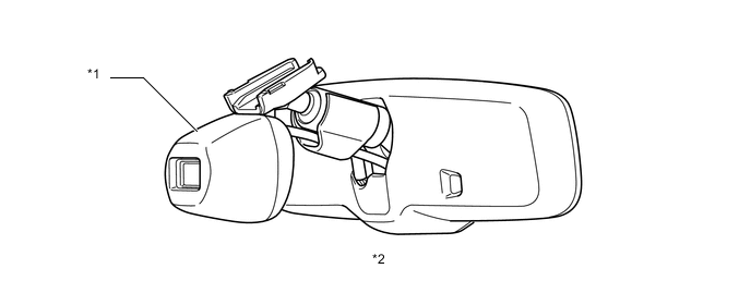
Text in Illustration *1 Automatic High Beam Sensor *2 Inner Rear View Mirror Assembly -
-
-
Adaptive High-beam System (AHS)
-
Adaptive High-beam Sensor (Inner Rear View Mirror Assembly)
-
The adaptive high-beam sensor consists of a Complementary Metal Oxide Semiconductor (CMOS) that receives images and a mirror portion that identifies light sources. The adaptive-high beam sensor sends information about the position of preceding and oncoming vehicles to the AHS ECU via the CAN communication system.
Text in Illustration *1 Adaptive High-beam Sensor *2 Inner Rear View Mirror Assembly -
-
Headlight Assembly
-
The headlight assembly includes the Adaptive High-beam System (AHS) light unit which is a projector headlight with both lo beam and hi beam functions, and which contains a LO/HI beam switching shade, LO/HI switching shade motor, half shade beam shade, half shade beam shade motor and headlight swivel motor.
-
The LO/HI beam switching shade and half shade beam shade have been combined to change between lo beam, hi beam and half shade beam. In addition, the half shade beam can be changed by the headlight swivel motor in a horizontal direction.
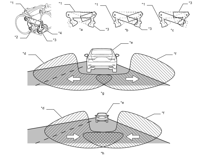
Text in Illustration *1 LO/HI Beam Switching Shade *2 LO/HI Beam Switching Motor *3 Half Shade Beam Shade *4 Half Shade Beam Shade Motor *a Lo Beam State *b Hi Beam State *c Half Shade Beam State *d Variable Shade Beam Lighting Area Image (LH Side) *e Preceding Vehicle *f Variable Shade Beam Lighting Area Image (RH Side) *g When the Vehicle is Approaching the Taillights of a Preceding Vehicle. *h When the Vehicle is Moving Away from the Taillights of a Preceding Vehicle. -
-
Combination Meter Assembly
-
When the Adaptive High-beam System (AHS) is activated, the combination meter assembly informs the driver by illuminating the adaptive high-beam indicator light.
-
When the hi beam headlights are on, the combination meter assembly informs the driver by illuminating the hi beam headlight indicator light.
-
If malfunctions occur in the AHS, the combination meter assembly warns the driver by indicating a message on the multi-information display, sounding the buzzer and illuminates the master warning light when receiving signals from the AHS ECU.
Text in Illustration *1 Multi-information Display *2 Master Warning Light *3 High Beam Headlight Indicator Light *4 Adaptive High-beam Indicator Light *a Warning Message - - -
-
-
Lane Change Flasher System
-
Turn Signal Switch (Headlight Dimmer Switch Assembly)
-
The lane change flasher system is operated by moving the turn signal switch to the lane change position.
-
After the turn signal switch has been moved to the lane change position, it will return to the neutral position once released from the hand.
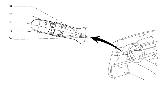
Text in Illustration *a Right Cornering Position *b Right Lane Change Position *c Neutral Position *d Left Lane Change Position *e Left Cornering Position - - -
-
-
-
FAIL-SAFE
-
LED Headlight System
-
The LED driver module executes the fail-safe actions listed below in accordance with the problem that has been detected:
Problem Outline Detection of Abnormal Input Voltage When the voltage that is input to the LED driver module deviates from the normal operating voltage (10 V to 16 V), the LED driver module stops illuminating the headlights. The LED driver module resumes illuminating the headlights once the voltage reverts to the normal operating voltage. However, if the input voltage decreases after the headlights have illuminated, the headlights remain illuminated until the input voltage becomes insufficient to light the LEDs. Detection of Abnormal Output (Open Circuit or Short Circuit) If an abnormal condition (open or short) occurs in the voltage that is output by LED driver module, the LED driver module stops operation and maintains this state until the power is reinstated. Power is reinstated by turning the light control switch from off to on.
-
-
Intelligent AFS and Automatic Headlight Beam Level Control System
-
If the headlight swivel ECU assembly detects a malfunction in the intelligent AFS or automatic headlight beam level control system, it will take the actions indicated in the table below:
Trouble Area System Operation Display* Intelligent AFS Automatic Headlight Beam Level Control System Headlight Swivel ECU Assembly Stops operating. Stops operating. Illuminates Speed Sensor Signal
-
If a malfunction occurs only at one of the wheels, the headlight swivel ECU doubles the vehicle speed detection value obtained from the normal wheel.
-
If malfunction occurs at all wheels, the headlight swivel ECU continues control only when the vehicle is stopped.
Stops operating after returning to the initial position. Illuminates Height Control Sensor Sub-assembly (Front, Rear) Stops operating after returning to the initial position.
-
Stops control after returning to the initial position (if failure occurs at higher than the initial position).
-
Stops control at current condition (if failure occurs at lower than the initial position).
Illuminates Steering Sensor Stops operating after returning to the initial position. Control is continued. Illuminates Headlight Swivel Motor The normal side swivel actuator comes to the initial position and the abnormal side swivel actuator stops in its current position.
-
Stops control after returning to the initial position (if failure occurs at higher than the initial position).
-
Stops control at current condition (if failure occurs at lower than the initial position).
Illuminates Communication Signal Stops operating after returning to the initial position. Control is continued. Illuminates Tech Tips
*: The master warning light illuminates and "Check Headlight System" is displayed on the multi-information display.
-
-
-