DOOR CLOSER SYSTEM
-
FUNCTION OF MAIN COMPONENTS
Component Function Door Closer Assembly Half/Full Latch Switch Determines the locations of fully-closed and half-shut doors and outputs them to the multiplex network door ECU. Temporary Stop Switch Determines the temporary stop position of the door closer system and outputs it to the multiplex network door ECU. Pawl Switch Detects the status of the pawl and outputs it to the multiplex network door ECU. Initial Position Switch Detects the initial position of the door closer motor and outputs it to the multiplex network door ECU. Handle Switch Detects the status of the door handle and outputs it to the multiplex network door ECU. Door Closer Motor Fully closes the doors by means of the signals from the multiplex network door ECU. Multiplex Network Door ECU Regulates the door closer motor based on the signals from each switch. -
OPERATING CONDITION
-
The operating conditions of the door closer system are as follows:
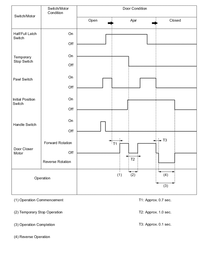
Component Function Operation Commencement When all the following conditions are met after the half/full latch switch has been off and the temporary stop switch has been on, operation will commence after approx. 0.7 seconds:
-
Half/full latch switch is on.
-
Temporary stop switch is on.
-
Pawl switch is turned from on to off.
-
Initial position switch is off.
-
Handle switch is off.
When the temporary stop switch is turned off after the operation starts, the door closer motor will be stopped for approx. 1 second.
Operation Completion When all the following conditions are met, operation will complete:
-
Half/full latch switch is off.
-
Temporary stop switch is off.
-
Pawl switch is off.
-
Initial position switch is on.
The reverse operation starts approx. 0.1 seconds after the operation completion conditions are met. When either of the following conditions is met, the reverse operation will complete:
-
Initial position switch is off.
-
Approx. 1.5 seconds have passed.
Operation Cancellation When any of the following conditions is met, the operation will be canceled.
-
Handle switch is on.
-
Half/full latch switch is off and temporary stop switch is on.
-
A current has been continuously applied to the motor for longer than a predetermined amount of time.
-
-
-
CONSTRUCTION
-
Door Closer Assembly
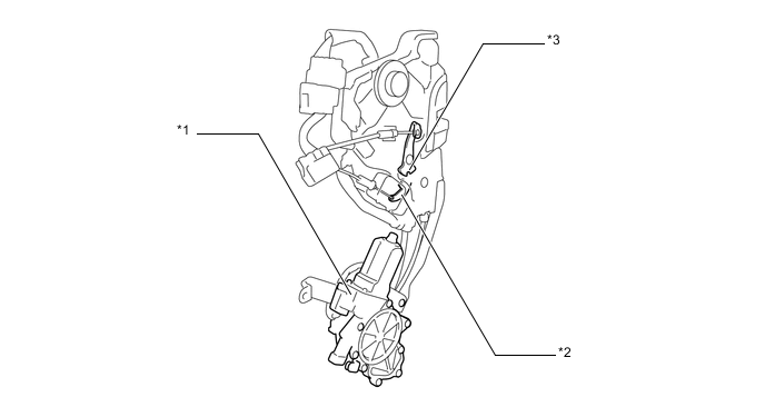
Text in Illustration *1 Door Closer Motor *2 Locking Lever (Lock Position Switch) *3 Door Lock Active Lever - - -
Mechanical Cancel Mechanism
-
The door closer system operates as follows. The motor worm gear rotates the worm wheel gear (sun gear). The sun gear incorporated in the worm wheel gear rotates the pinion gears. When the pinion gears rotate, the pinion gear plate which secures the pinion gears, and the output shaft also rotate, reducing the speed of rotation. As a result, the close cable is pulled via the output lever and the latch lever rotates. The latch lever pushes and turns the latch so that the striker can be pulled in by the latch.
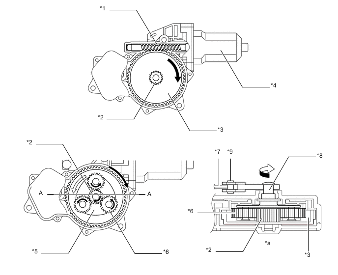
Text in Illustration *1 Worm Gear *2 Sun Gear *3 Worm Wheel Gear *4 Motor *5 Plate *6 Pinion Gear *7 Close Cable *8 Output Shaft *9 Output Lever - - *a A - A Cross Section - - -
In the door closer system, operating the inside or outside door handle assembly pulls the cancel lever through use of the cancel cable. When the cancel lever is pulled, the cancel gear and ring gear are disengaged, causing the ring gear to be released. As a result, the pinion gears rotate freely and output to the output lever is cut off. This cancels the system and allows the door to be opened regardless of the state of the system.
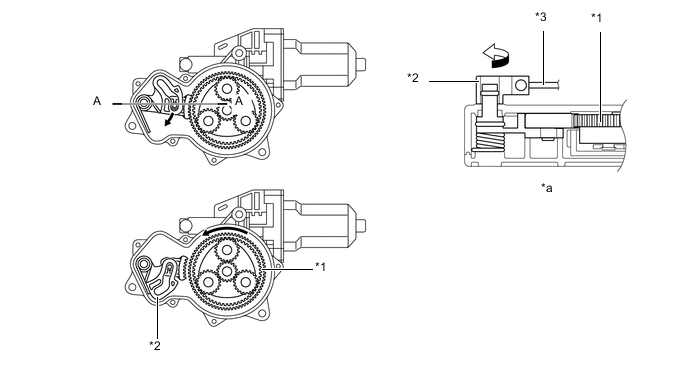
Text in Illustration *1 Ring Gear *2 Cancel Lever *3 Cancel Cable - - *a A - A Cross Section - - Note
If the child lock of a rear door is engaged, it cannot be canceled by operating the inside door handle.
-
-
-
OPERATION
-
Multiplex Network Door ECU
-
In the door closer system, the transition of the door from the open state to the ajar state is detected by the multiplex network door ECU. The ECU then actuates the door closer motor to rotate the latch in order to fully close the door. This ECU, which is provided in each of the doors, independently controls the respective door. The multiplex network door ECUs maintain communication via the CAN (MS bus).
-
When the system is activated, if the multiplex network door ECU detects an abnormal condition, it outputs the applicable Diagnostic Trouble Code (DTC). The DTC can only be accessed through the use of the Global TechStream (GTS).
-
-
-
FAIL-SAFE
-
The multiplex network door ECU stops the system if it detects a malfunction in the system. However, the doors can be opened or closed manually even if the closer system is not operating.
-