CLIMATE CONTROL SEAT SYSTEM
-
FUNCTION OF MAIN COMPONENTS
-
Climate Control Seat System
Component Outline Climate Control Seat Switch Operates the climate control seat system. Climate Control ECU Assembly
-
Operates the seat climate control blower in accordance with signals from the climate control seat switch.
-
Operates the seat heater in accordance with signals from the climate control seat switch.
-
Controls the climate control seat system based on signals from the air conditioning amplifier assembly.
Air Conditioning Amplifier Assembly Sends ambient temperature and air conditioning temperature signals to the climate control ECU assembly. Climate Control Blower Assembly Operates in accordance with signals from the climate control ECU assembly. Seat Climate Control Controller Cools air by passing it through the built-in TED indicate Peltier elements. -
-
-
OPERATING CONDITION
-
When all of the following conditions are met, the quick seat heater control operates after the power switch is turned on (IG):
Condition
-
1 second or more has elapsed since the power switch was turned on (IG).
-
The ambient temperature is 20°C (68°F) or less.
-
The temperature of the seat surface is 20°C (68°F) or less.
-
The climate control seat system has been set to the manual heater control using the climate control seat switch or by automatic heater mode.
-
-
When any one of the following conditions is met, the quick seat heater control is canceled and the climate control seat system operates normally:
-
Except when the climate control seat system has been set to the manual heater control using the climate control seat switch or by automatic heater mode.
-
When the quick seat heater control reaches the end of its timer*1 sequence.
-
When the temperature of the seat surface increases to a certain degree as shown in the following table:
Climate Control Seat System Control*2 Temperature of Seat Surface Manual Heater Automatic Heater -5°C (23°F) or Less*3 Between -4°C (25°F) and 10°C (50°F)*3 11°C (52°F) or More*3 Max Max 52°C (126°F)*4
50°C (122°F)*5
47°C (117°F)*4
45°C (113°F)*5
42°C (108°F)*4
40°C (104°F)*5
- Mid3 49°C (120°F)*4
48°C (118°F)*5
44°C (111°F)*4
43°C (109°F)*5
39°C (102°F)*4
38°C (100°F)*5
Mid Mid2 46°C (115°F)*4
45°C (113°F)*5
41°C (106°F)*4
40°C (104°F)*5
36°C (97°F)*4
35°C (95°F)*5
- Mid1 43°C (109°F)*4
42°C (108°F)*5
38°C (100°F)*4
37°C (99°F)*5
33°C (91°F)*4
32°C (90°F)*5
Min Min 40°C (104°F) 35°C (95°F) 30°C (86°F) Tech Tips
*1: The settings of the timer can be customized. For details on customization, refer to the Repair Manual.
*2: Operation conditions of the climate control seat system while the quick seat heater control is in operation
*3: Temperature of the seat surface while the quick seat heater control is in operation
*4: For front climate control seat system
*5: For rear climate control seat system
-
-
-
FUNCTION
-
The following controls are used to operate the climate seat control system:
Control Outline Manual Control Heating, air conditioning or airflow*1 can be adjusted and operated using the climate control seat switch. Automatic Control This control is activated by setting the front climate control seat switch to the AUTO position and automatically operates the climate control seat system in accordance with the ambient temperature and front seat air conditioning target airflow temperature.*1 This control is activated by turning on the automatic switch located on the rear climate control seat switch and automatically operates the climate control seat system in accordance with the ambient temperature and rear seat air conditioning target airflow temperature.*2 Quick Seat Heater Control
-
This control temporarily increases the power of the seat heater in accordance with the ambient temperature, seat surface temperature, etc., after the power switch is turned on (IG) when the climate control seat system is set to the heater mode, and quickly warms the seat heater.
-
Once the timer reaches 180 seconds, this control operates normally.*3
-
*1: For front climate control seat system
-
*2: For rear climate control seat system
-
*3: The settings of the timer can be customized. For details on customization, refer to the Repair Manual.
-
-
Manual Control
-
The manual control operates heating, air conditioning and airflow in response to the climate control seat switch as follows:
Mode Outline Heater Mode For Front Climate Control Seat System Operates the seat heater in 3 stages between MIN, MID and MAX in response to the position of the switch when the climate control seat switch is in the Hot position. For Rear Climate Control Seat System
-
Changes the operation status (MIN → MID → MAX) every time the up switch of the climate control seat switch is turned on in order to operate the seat heater in accordance with the operation conditions.
-
Illuminates the red indicator light in accordance with the stage.
Cooler Mode For Front Climate Control Seat System Cools the air, which is sent in 3 stages (MIN, MID and MAX) in response to the position of the switch, through the Peltier element and blows it when the climate control seat switch is in the Cool position For Rear Climate Control Seat System
-
Changes the operation status (MIN → MID → MAX) every time the down switch of the climate control seat switch is turned on, cools air sent in accordance with the operation conditions through the peltier element and blows the air.
-
Illuminates the blue indicator light in accordance with the stage.
Airflow Mode For Front Climate Control Seat System Sends air when the switch is set to the airflow position. -
-
Heater Mode
-
The following seat heater temperatures can be set by operating the climate control seat switch:
Seat Heater Temperature MIN MID MAX Front Climate Control Seat System 33°C (91°F) 39°C (102°F) 45°C (113°F) Rear Climate Control Seat System 33°C (91°F) 38°C (100°F) 43°C (109°F)
-
-
Cooler Mode
-
The volume of the cool air can be adjusted in 3 stages by operating the climate control seat switch.
-
-
Airflow Mode
-
The front climate control seat system sends air when the front climate control seat switch is set to the airflow position.
-
-
-
Automatic Control
-
The automatic control has the following mode operations:
Mode Outline Automatic Heater Mode Automatically adjusts the temperature of the seat heater in 6 stages (off, min, mid 1, mid 2, mid 3 and max) in accordance with the ambient temperature, the air conditioning target airflow temperature, the time elapsed after the power switch is turned on (IG), etc., when the front climate control seat switch is in the AUTO position*1 or when the automatic switch of the rear climate control seat switch is on*2.
-
Front climate control seat system : [MIN : 33°C (91°F), MID 1 : 36°C (97°F), MID 2 : 39°C (102°F), MID 3 : 42°C (108°F), MAX : 45°C (113°F)]
-
Rear climate control seat system : [MIN : 33°C (91°F), MID 1 : 35°C (95°F), MID 2 : 38°C (100°F), MID 3 : 41°C (106°F), MAX : 43°C (109°F)]
Automatic Cooler Mode Automatically adjusts the volume of cool airflow in 5 stages (off, airflow*3, min, mid and max) in accordance with the ambient temperature, the air conditioning target airflow temperature, the time elapsed after the power switch is turned on (IG), etc., when the front climate control seat switch is in the AUTO position*1 or when the automatic switch of the rear climate control seat switch is on*2. Tech Tips
*1: For front climate control seat system
*2: For rear climate control seat system
*3: Airflow only
-
-
-
-
CONSTRUCTION
-
Climate Control Blower
-
When the user operates the climate control seat switch, the seat back climate control blower* and seat climate control blower operate to direct the air that is drawn in from behind the climate control blower to both the seat back* and seat cushion pads.
-
After the air is directed to both the seat back* and seat cushion pads, it travels throughout the pads along the grooves that are provided in the pads. Then, the air is discharged through the perforations in the pads.
-
*: Models with rear climate control seat system
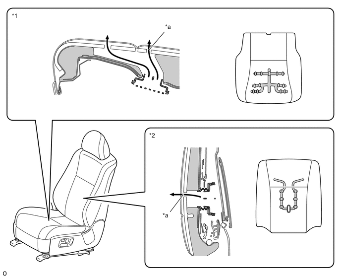
Text in Illustration (for Front Climate Control Seat System:) *1 Seat Cushion *2 Seat Back *a Airflow - - 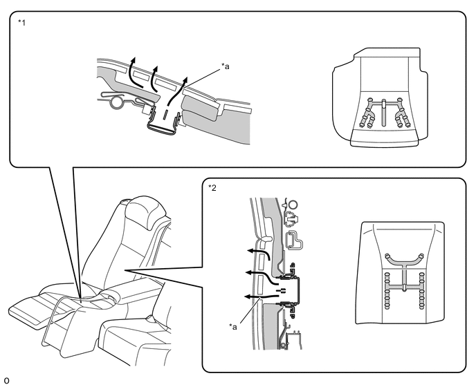
Text in Illustration (for 4-passenger Models with Rear Climate Control Seat System:) *1 Seat Cushion *2 Seat Back *a Airflow - - 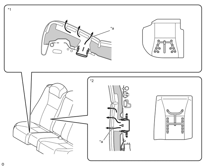
Text in Illustration (for 5-passenger Models with Rear Climate Control Seat System:) *1 Seat Cushion *2 Seat Back *a Airflow - - -
-
-
Front Climate Control Seat Switch
-
The indicator light of the front climate control seat switch illuminates when the front climate control seat system is operating.
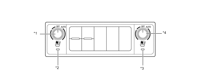
Text in Illustration *1 Front Climate Control Seat Switch LH *2 Indicator Light LH *3 Indicator Light RH *4 Front Climate Control Seat Switch RH
-
-
Rear Climate Control Seat Switch
-
The volume indicator light is turned on in response to the usage condition of the rear climate control seat system while the rear climate control seat system is being used.
-
The automatic indicator light illuminates when the automatic switch is turned on.
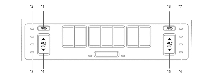
Text in Illustration *1 Automatic Switch LH *2 Automatic Indicator Light LH *3 Volume Indicator Light LH *4 Rear Climate Control Seat Switch LH *5 Rear Climate Control Seat Switch RH *6 Volume Indicator Light RH *7 Automatic Indicator Light RH *8 Automatic Switch RH -
The volume indicator light illuminates as follows when the system is operating under manual control:
Mode Cooler Mode Off Heater Mode Operation MAX MID MIN MIN MID MAX Illuminates Color Blue - Red Illuminates Operation 


-
The automatic indicator light illuminates when the system is operating under automatic control and the volume indicator light illuminates as follows:
Mode Cooler Mode Off Heater Mode Operation Air Flow MIN MID MAX MIN MID 1 MID 2 MID 3 MAX Illuminates Color Blue - Red Illuminates Operation
-
-
-
FAIL-SAFE
-
Fail-safe control effects the following 3 controls:
-
Overcurrent Protection Control
-
Transient Voltage Drop Control
-
Temperature Sensor Open/Short Detection Control
-
-
Overcurrent Protection Control
-
Areas for detecting overcurrent are provided in the seat climate control controller. The climate control seat system stops or reinstates when the conditions listed below have been met.
Climate Controller Detection Condition When both conditions listed below have been met:
-
The climate control seat switch is on (without airflow mode).
-
The amount of current provided for the climate controller actuation has exceeded 10 A for 2 seconds or more.
Reinstatement Condition When the climate control seat switch is turned off, the indicator light turns off, and the switch is operated, the indicator light operates in accordance with the volume.
-
The power switch is turned to off then back to on (IG).
-
-
-
Transient Voltage Drop Control
-
When the power source voltage of the climate control seat ECU has met the conditions listed below, this control stops or is reinstated.
Detection Condition When both conditions listed below have been met:
-
The climate control seat switch is on.
-
Continuously drops below approximately 8 V for approximately 10 msec.
Reinstatement Condition The control is reinstated when system control resumes in accordance with the volume setting of the climate control seat switch and when the power voltage of the ECU reaches above approximately 10 V continuously for approximately 10 msec. -
-
-
Temperature Sensor Open/Short Detection Control
-
When the voltage of the temperature sensors that is supplied to the input signal terminals (TBS, TCS and HS) meets the conditions listed below, this control stops or is reinstated.
Temperature Sensor (for Climate Control) Detection Condition The temperature sensor detection value is 110°C (230°F) or more or -40°C (104°F) or less for 8 consecutive seconds. Temperature Sensor (for Seat Heater) Detection Condition When both conditions listed below have been met:
-
The climate control seat switch is on (without airflow mode).
-
The amount of current provided for the climate controller actuation has exceeded 10 A for 2 seconds or more.
Reinstatement Condition The temperature sensor detection value is 110°C (230°F) or more or -40°C (104°F) or less for 8 consecutive seconds. -
-
-
-
DIAGNOSIS
-
If the climate control seat system malfunctions, the system stops its function and a Diagnostic Trouble Code (DTC) is stored in the climate control ECU. The DTC can be read by connecting an Global TechStream (GTS) to the DLC3. For details, refer to the Repair Manual.
-