VARIABLE GEAR RATIO STEERING SYSTEM
-
FUNCTION OF MAIN COMPONENTS
Component Function Steering Actuator Assembly Motor Rotates to create the operating angle of the steering actuator assembly upon receiving the signals from the steering control ECU. Rotation Angle Sensor Outputs the rotational angle of the motor to the steering control ECU. Lock Solenoid Locks the motor shaft so that the motor will not rotate in case of a system malfunction. Reduction Mechanism Uses a strain wave gear type reduction mechanism to reduce the rotation of the motor to the 1:51 ratio. Combination Meter Assembly Multi-information Display Displays the warning message to inform the driver of a malfunction in the system. Master Warning Light Illuminates when the warning message is displayed in the multi-information display. Multi Buzzer Sounds to warn the driver of a malfunction in the system. Steering Sensor Detects the steering direction and angle of the steering wheel. Steering Control ECU Operates the motor by calculating the operating angle of the steering actuator assembly based on the signals from the steering angle sensor and each ECU. Power Steering ECU Assembly Sends the steering assist signal to the steering control ECU. Suspension Control ECU Outputs the damping force control condition. Skid Control ECU Assembly
-
Outputs the vehicle speed signal.
-
Requests the steering control (EPS system and VGRS system) during cooperative control.
Hybrid Vehicle Control ECU Sends information about the drive mode selected by the drive mode select to each ECU. Driving Support ECU Assembly
(Models with Pre-crash Safety System)
Requests the steering control (EPS system and VGRS system) during cooperative control. -
-
SYSTEM CONTROL
-
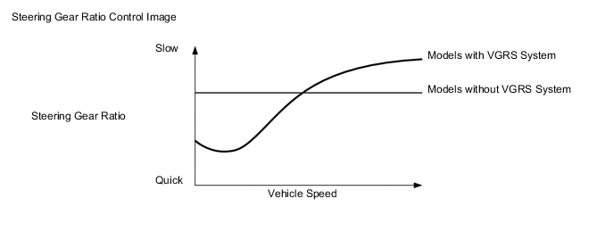
The steering control ECU calculates the steering actuator assembly target operating angle in accordance with the steering sensor signal and vehicle speed signal.
-
The steering control ECU controls the turning angle of the front wheels by adding the operating angle of the steering actuator assembly to the angle to which the steering wheel is steered by the driver. As a result, the steering gear ratio fluctuates depending on the driving conditions. Thus, excellent steering feel and vehicle stability are achieved, regardless of the vehicle speed, from the low- to high-speed ranges.
-
The steering control ECU calculates the steering speed based on the steering sensor signal and corrects the steering actuator assembly operating angle, thus improving steering response.
-
If a vehicle that is being driven straight ahead over a road surface with different friction coefficients brakes suddenly and causes the VSC to activate, the vehicle posture will become disrupted, thus requiring the driver to operate the steering wheel. When this occurs, the skid control ECU assembly transmits signals to the steering control ECU. When the steering control ECU receives these signals, it calculates the target operating angle for the steering actuator assembly based on the driver's steering angle and direction and the vehicle speed signal. Then, the VGRS system operates, reducing the driver's steering effort.
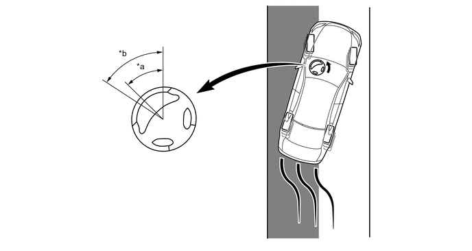
Text in Illustration *a Driver's steering wheel angle under the control with a signal from the skid control ECU *b Driver's steering wheel angle under the control without a signal from the skid control ECU 
Slippery Surface - -
-
-
CONSTRUCTION
-
Steering Actuator Assembly
-
The steering actuator assembly is incorporated into the power steering link assembly.
-
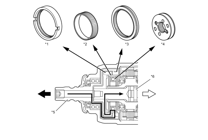
The steering actuator assembly consists of a housing, a motor, a reduction mechanism, an output shaft, and a lock mechanism.
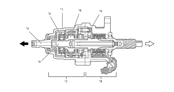
Text in Illustration *1 Housing *2 Reduction Mechanism *3 Input Shaft *4 Output Shaft *5 Lock Mechanism *6 Motor *7 Steering Actuator Assembly *8 Torque Sensor 
Steering Wheel Side 
Power Steering Link Assembly Side
-
-
Motor
-
A compact, high power output, and low noise brushless type motor is used. This motor is enclosed in the housing.
-
This motor mainly consists of a magnet, a coil, and a motor shaft. The motor shaft is coupled to the wave generator of the reduction mechanism in order to transmit the rotational movement of the motor to the reduction mechanism.
-
This motor, which is controlled by the signal from the steering control ECU, rotates either clockwise or counterclockwise, depending on the direction in which the steering wheel is turned.
-
The rotation angle sensor detects the rotational direction and rotational angle of the motor.
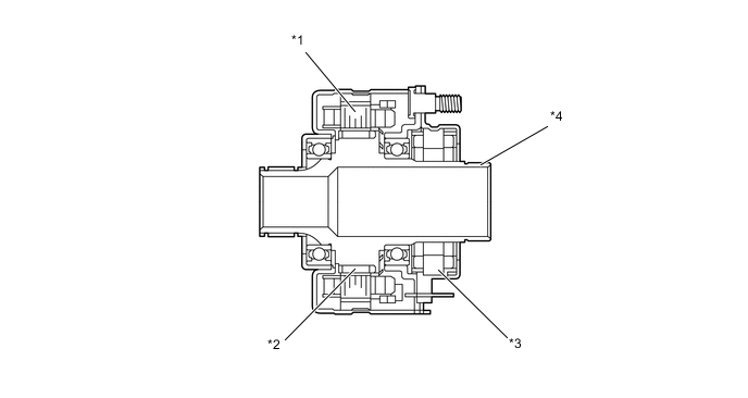
Text in Illustration *1 Coil *2 Magnet *3 Rotation Angle Sensor *4 Motor Shaft
-
-
Reduction Mechanism
-
The reduction mechanism uses strain wave gearing, which is compact and highly accurate, and creates a large reduction gear ratio (1:51) using a small number of components.
-
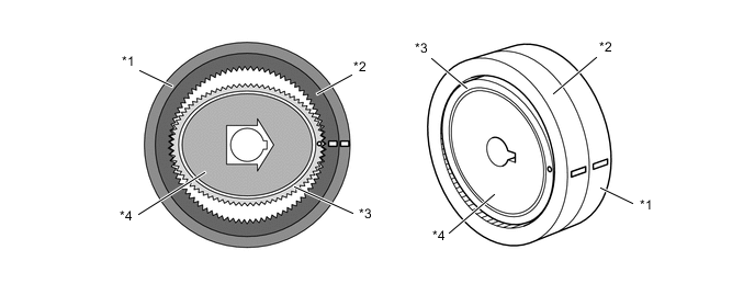
This reduction mechanism consists of a driven gear, a stator gear, a flexible gear, and a wave generator.
Text in Illustration *1 Stator Gear *2 Flexible Gear *3 Driven Gear *4 Wave Generator *5 Input Shaft *6 Output Shaft Steering Wheel Side Power Steering Link Assembly Side Construction of Reduction Mechanism Item Construction Stator Gear (Input)
-
Has a rigid body and a ring shape, and contains 102 teeth along the inner circumference.
-
Positioned parallel to the driven gear.
-
Coupled to the housing of the steering actuator assembly.
Driven Gear (Output)
-
Has a rigid body and a ring shape, and contains 100 teeth along the inner circumference.
-
Positioned parallel to the stator gear.
-
Coupled to the output shaft of the steering actuator assembly.
Flexible Gear
-
Has a flexible metal body that forms a belt shape and contains 100 teeth along the outer circumference.
-
Located outside of the wave generator, and positioned in such a way that its gear teeth are meshed with the inside of both the stator gear and the driven gear.
Wave Generator
-
Consists of an oval-shaped cam and a ball bearing that is fitted around the cam.
-
Coupled to the motor shaft of the motor and rotates inside the flexible gear while pushing the flexible gear against the stator gear and the driven gear.
-
-
-
Lock Mechanism
-
This system contains a lock mechanism that mechanically locks the motor so that the motor will not rotate if a malfunction occurs. Along with this, the housing and the output shaft are integrated.
-
The lock mechanism is mounted on the motor. The mechanism consists primarily of a lock holder that is secured to the motor shaft, a lock lever that is mounted on the housing, and a lock solenoid that operates the lock lever.
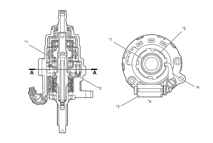
Text in Illustration *1 Motor Shaft *2 Lock Holder *3 Lock Solenoid *4 Lock Lever *a A - A Cross Section - - -
When the lock mechanism is activated, the steering control ECU turns off the current to the lock solenoid, and the return spring pushes the lock lever against the lock holder. Then, the lock lever meshes with the groove in the lock holder in order to mechanically lock the movement of the motor. When the lock is disengaged, the steering control ECU turns on the current to the lock solenoid, thus disengaging the lock lever and the lock holder and freeing the movement of the motor.
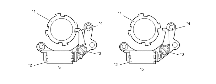
Text in Illustration *1 Lock Holder *2 Lock Solenoid *3 Return Spring *4 Lock Lever *a Unlock State (Lock Solenoid On) *b Lock State (Lock Solenoid Off)
-
-
-
OPERATION
-
Reduction Mechanism Operation
-
The flexible gear is fitted inside the driven gear and stator gear as illustrated. Furthermore, the wave generator is fitted inside the flexible gear. The rotational movement of the wave generator causes the flexible gear to become deformed into an oval shape. The teeth at the major axis of the oval shape mesh with the teeth of the driven gear and stator gear, and the teeth at the minor axis are disengaged.
Text in Illustration *1 Driven Gear *2 Stator Gear *3 Flexible Gear *4 Wave Generator -
When the stator gear is fixed and the wave generator rotates clockwise, the flexible gear undergoes an elastic deformation. This causes the meshed areas between the flexible gear, driven gear and stator gear to move consecutively.
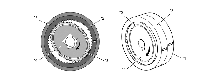
Text in Illustration *1 Driven Gear *2 Stator Gear *3 Flexible Gear *4 Wave Generator -
When the wave generator makes 1 rotation, the flexible gear moves counterclockwise by 2 teeth because it has 2 fewer teeth than the stator gear. The driven gear and the flexible gear have the same number of teeth, so their rotational movements are identical. Therefore, the driven gear (output) moves by 2 teeth.
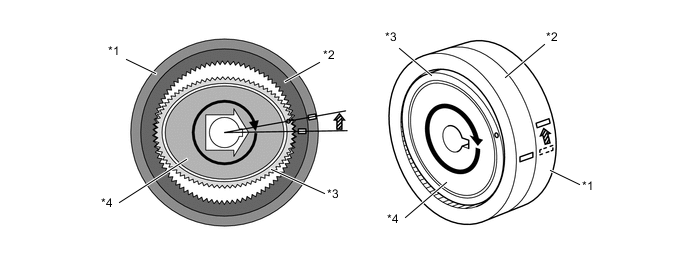
Text in Illustration *1 Driven Gear *2 Stator Gear *3 Flexible Gear *4 Wave Generator 
Stator Gear Move Clockwise by 2 Teeth - -
-
-
System Operation
-
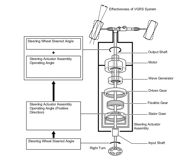
This system rotates the steering actuator assembly in the positive direction in the low speed range (in which a reduction in the steering wheel operating angle is desired) or in the medium speed range (in which an agile vehicle response is desired).
-
When the driver turns the steering wheel clockwise, the steering control ECU rotates the motor in the steering actuator assembly clockwise.
-
Then, the rotational movement of the motor is input into the reduction mechanism by way of the wave generator. The rotational movement is reduced to a 1:51 gear ratio, and is output from the output shaft in the clockwise direction. This operating angle of the steering actuator assembly is then added to the angle in which the steering wheel is steered by the driver. Thus, the output shaft rotates more clockwise than the actual steered angle of the steering wheel by the operation of the steering actuator assembly. As a result, the front wheels turn more to the right.
-
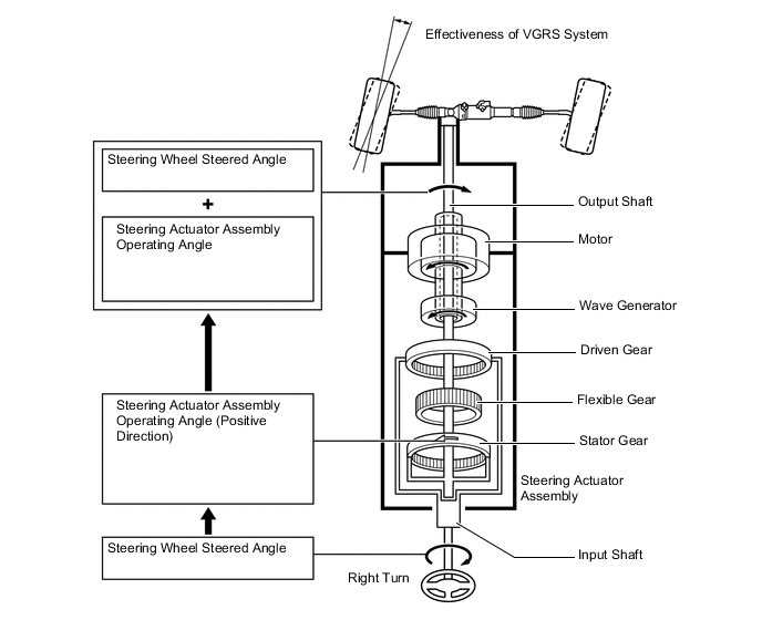
This system rotates the steering actuator assembly in the negative direction in the high speed range (in which an over-sensitive movement response of the vehicle is not desired).
-
When the driver turns the steering wheel clockwise, the steering control ECU rotates the motor in the steering actuator assembly counterclockwise.
-
Then, the rotational movement of the motor is input into the reduction mechanism by way of the wave generator. The rotational movement is reduced to a 1:51 gear ratio, and is output a little from the output shaft in the counterclockwise direction. This operating angle of the steering actuator assembly is then subtracted from the angle in which the steering wheel is steered by the driver. Thus, the output shaft does not rotate as far clockwise as the actual steered angle of the steering wheel by the operation of the steering actuator assembly. As a result, the front wheels turn less to the right.
-
-
-
FAIL-SAFE
-
If a system malfunction occurs, the steering control ECU turns off the lock solenoid of the lock mechanism and locks the motor in the steering actuator assembly.
-
-
DIAGNOSIS
-
If the steering control ECU detects a malfunction in the VGRS system, it lights up the master warning light, indicates the warning message on the multi-information display, sounds the multi buzzer to alert the driver of the malfunction.
-
The steering control ECU will also store a Diagnostic Trouble Code (DTC). The DTC can be accessed through the use of a Global TechStream (GTS). For details, refer to the Repair Manual.
-