POWER STEERING SYSTEM
-
FUNCTION OF MAIN COMPONENTS
Component Function Power Steering Link Assembly Reduction Mechanism Reduces the speed of the motor and transmits the rotation of the motor to the rack shaft. Torque Sensor Converts the twist of the steering torsion bar into an electrical signal and sends this value to the power steering ECU assembly. Rotation Angle Sensor Transmits the rotation angle of the motor to the power steering ECU assembly. Motor Generates power assist in accordance with the actuation current received from the power steering ECU assembly. Combination Meter Assembly Power Steering Warning Light Illuminates to alert the driver when the power steering ECU assembly detects a malfunction in the EPS system. Multi-information Display Displays the warning message to inform the driver of a malfunction in the EPS system. Master Warning Light Illuminates when the warning message is displayed on the multi-information display. Multi Buzzer Sounds to warn the driver when the system is malfunction. Power Steering Converter Assembly
-
Converts the voltage of HV battery from 288 V to 46 V and supplies this power source to the motor via the power steering ECU assembly.
-
When there are any HV battery voltage problems, it temporarily converts the auxiliary battery voltage and supplies electrical power to the power steering ECU assembly.
Steering Sensor Detects the steering direction and angle of the steering wheel. Power Steering ECU Assembly
-
Actuates the motor to provide power assist, based on the signals received from various sensors and ECUs.
-
Outputs a warning signal to the combination meter assembly when the power steering ECU assembly detects an EPS system malfunction.
Steering Control ECU Transmits the operation angle of the steering actuator assembly to the power steering ECU assembly. Skid Control ECU Assembly
-
Outputs the vehicle speed signal.
-
Requests steering torque assist during cooperative control.
Suspension Control ECU Transmits the drive mode select signal to the power steering ECU assembly. Hybrid Vehicle Control ECU Outputs the control enabling signal to the power steering converter assembly in accordance with the HV battery voltage. Driving Support ECU Assembly
(Models with Pre-crash Safety System)
Requests steering torque assist during system control. -
-
SYSTEM CONTROL
Control Outline Steering Assist Control Basic Control Calculates the assist current required based on the steering torque value and the vehicle speed and actuates the motor. Inertia Compensation Control Improves the starting movement of the motor when the driver starts to turn the steering wheel. Recovery Control Assists the recovery force during the short interval between the time the driver fully turns the steering wheel and the time the wheels try to recover. Damper Control Regulates the amount of assist when the driver turns the steering wheel while driving at high speeds, thus damping the changes in the yaw rate of the vehicle body. System Overheat Protection Control Estimates the motor temperature based on the amperage and the current duration. If the temperature exceeds the standard, it limits the amperage to prevent the motor from overheating. SPORT Mode Control Actuates steering assist control when in SPORT S+ mode to increase steering feedback beyond normal levels. Brake Control System Cooperative Control Receives requests from the skid control ECU and actuates steering assist control in accordance with the operating condition of the brake control system. This facilitates the steering operation of the driver, thus achieving a high level of vehicle stability. Lane-keeping Assist System Cooperative Control
(Models with Lane-keeping Assist System)
When the vehicle is about to deviate from the lane or the vehicle is being assisted to keep the lane, the lane-keeping assist system assists steering in accordance with the signal from the driving support ECU. Power Supply Voltage Drop Control
-
When the power steering ECU assembly detects a power supply voltage drop, it illuminates the power steering warning light while moderating fluctuations in the steering assist torque and controls the steering assist control.
-
When the power steering ECU assembly detects a power supply voltage drop, it sends a load control demand to the air conditioning amplifier assembly in order to limit electrical usage.
-
-
FUNCTION
-
Drive Mode Select
-
The steering assist control mode can be selected by operating the drive mode select.
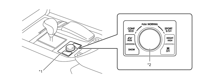
Text in Illustration *1 Combination Switch Assembly *2 Drive Mode Select -
The power steering ECU assembly changes the steering assist control mode (NORMAL or SPORT) in accordance with the selected drive mode.
-
When the steering assist control mode is in SPORT, the steering assist volume is reduced more than when in NORMAL, thus achieving a firm steering feeling optimal for a sporty drive.
Drive Mode (Drive Mode Select Position) Steering Assist Control Mode SPORT S+ SPORT SPORT S NORMAL NORMAL NORMAL COMFORT NORMAL ECO NORMAL
-
-
-
CONSTRUCTION
-
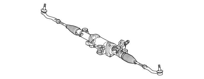
Power Steering Link Assembly
-
The power steering link assembly consists of a rack shaft, reduction mechanism, pinion gear, torsion bar, motor and torque sensor.
-
-
Motor and Reduction Mechanism
-
The motor is a high power output and brushless type.
-
The motor is located around the rack shaft. The motor consists of a rotation angle sensor, magnet, coil, stator, and rotor.
-
The reduction mechanism consists of balls and a ball screw nut. The balls and ball contact surfaces are processed with a high degree of accuracy to achieve high efficiency and low noise.
-
The ball screw nut secured to the rotor transmits rotational torque from the rotor to the balls. The balls then transmit the rotational torque to the rack shaft.
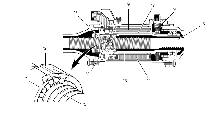
Text in Illustration *1 Ball *2 Ball Screw Nut *3 Rotor *4 Stator *5 Rack Shaft *6 Rotation Angle Sensor *7 Magnet *8 Coil
-
-
Torque Sensor
-
The torque sensor consists of 2 resolver sensors (resolver sensor 1 and resolver sensor 2).
-
Resolver sensor 1 is mounted on the input side of the main shaft. Resolver sensor 2 is mounted on the output side of the pinion shaft.
-
These resolver sensors convert twisting force on the input and output sides of the torsion bar into electric signals and transmit these signals to the power steering ECU assembly.
-
The signals sent from the input and output sides differ depending on the amount of twisting force. The power steering ECU assembly calculates the torque value based on the differences in these signals.
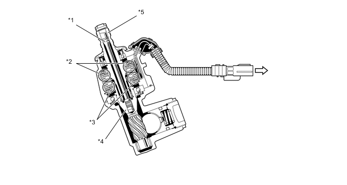
Text in Illustration *1 Torsion Bar *2 Resolver Sensor 1 *3 Resolver Sensor 2 *4 Pinion Shaft *5 Main Shaft - - 
To Power Steering ECU Assembly - - -
If the vehicle is driven straight and the driver does not turn the steering wheel, the specified voltage that is output at this time is determined by the power steering ECU assembly to indicate the neutral position of the steering wheel. Therefore, the power steering ECU assembly does not apply power current to the motor.
-
When the driver turns the steering wheel, a relative angle difference is created between the rotor portions of the resolver sensor 1 and resolver sensor 2, only in the amount that is equivalent to the twisting of the torsion bar.
-
The stator portions of the resolver sensor 1 and resolver sensor 2 receive the angles of the rotors in the form of electric signals and output them to the power steering ECU assembly. Based on these input signals, the power steering ECU assembly calculates the relative angle difference between the angles detected by the 2 resolver sensors.
-
The power steering ECU assembly calculates the torque value based on that difference. Then, the power steering ECU assembly calculates the assist power current based on the calculated torque value and vehicle speed. Based on the information obtained from the rotation angle sensor, the power steering ECU assembly actuates the motor at a predetermined current.
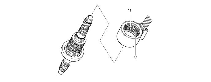
Text in Illustration *1 Resolver Sensor 1 *2 Resolver Sensor 2 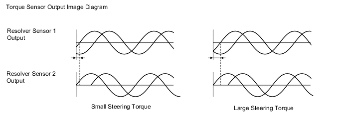
-
-
-
FAIL-SAFE
-
If the power steering ECU assembly detects a malfunction in the EPS system, it lights up the power steering warning light and master warning light, and displays the warning massage on the multi-information display to alert the driver of the malfunction.
-
If a system malfunction occurs, the power steering ECU assembly changes control mode to fail-safe mode. For details, refer to the Repair Manual.
-
-
DIAGNOSIS
-
If the power steering ECU assembly detects a malfunction in the EPS system, it lights up the power steering warning light and master warning light, and displays the warning message on the multi-information display to alert the driver of the malfunction.
-
The power steering ECU assembly will also store a Diagnostic Trouble Code (DTC). The DTC can be accessed through the use of a Global TechStream (GTS). For details, refer to the Repair Manual.
-