ACTIVE STABILIZER SUSPENSION SYSTEM
-
FUNCTION OF MAIN COMPONENTS
Component Function Front Active Stabilizer Control Actuator Assembly Twists the stabilizer bar in accordance with the signals received from the front active stabilizer control ECU assembly in order to control the roll angle of the vehicle. Rear Active Stabilizer Control Actuator Assembly Twists the stabilizer bar in accordance with the signals received from the rear active stabilizer control ECU assembly in order to control the roll angle of the vehicle. HV Battery Provides stable electrical power to the power steering converter assembly. Power Steering Converter Assembly Converts the HV battery voltage upon receiving signals from the hybrid vehicle control ECU and supplies electrical power to the front and rear active stabilizer control ECU assemblies. Steering Sensor Detects the steering direction and angle of the steering wheel. Yawrate Sensor
(with Built-in Deceleration Sensor)
-
Detects the vehicle's longitudinal and lateral acceleration.
-
Detects the vehicle's yaw rate.
Front Active Stabilizer Control ECU Assembly
-
Calculates the target twist angle of the front active stabilizer control actuator assembly and actuates the front active stabilizer control actuator assembly in accordance with the signals received from the sensors.
-
Communicates with the rear active stabilizer control ECU assembly to keep optimally balancing the twist angles of both the front and rear active stabilizer control actuator assemblies.
Rear Active Stabilizer Control ECU Assembly
-
Calculates the target twist angle of the rear active stabilizer control actuator assembly and actuates the rear active stabilizer control actuator assembly in accordance with the signals received from the sensors.
-
Communicates with the front active stabilizer control ECU assembly to keep optimally balancing the twist angles of both the front and rear active stabilizer control actuator assemblies.
Hybrid Vehicle Control ECU Outputs the control enabling signal to the power steering converter assembly in accordance with the HV battery voltage. Skid Control ECU Assembly Transmits the vehicle speed signal to the front and rear active stabilizer control ECU assemblies. Steering Control ECU Transmits the operation angle of the steering actuator assembly to the front and rear active stabilizer control ECU assemblies. Suspension Control ECU Transmits the drive mode select signal to the front and rear active stabilizer control ECU assemblies. Combination Meter Assembly Multi-information Display Displays a warning message when the front and rear active stabilizer control ECU assemblies detect a malfunction in the system. Master Warning Light Illuminates to warn the driver of a malfunction in the system. Multi Buzzer Sounds to warn the driver of a malfunction in the system. -
-
SYSTEM CONTROL
-
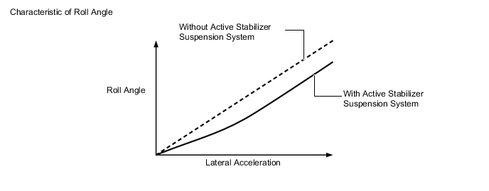
The front and rear active stabilizer control ECU assemblies calculate the lateral acceleration of the vehicle from the signals received from the steering angle sensor, yawrate sensor, skid control ECU assembly (vehicle speed signals) and steering control ECU (steering actuator assembly operating angle signals).
-
The front and rear active stabilizer control ECU assemblies decrease the vehicle roll angle caused by lateral acceleration during cornering by controlling the twist angle of the front and rear active stabilizer control actuator assemblies. As a result, excellent vehicle stability has been achieved. In addition, the front and rear active stabilizer control ECU assemblies synchronize the front and rear roll angles through mutual communication, thus ensuring excellent cornering performance.
-
When SPORT S+ drive mode is selected by the drive mode select, the front and rear active stabilizer control ECU assemblies receive SPORT S+ drive mode signals from the suspension control ECU and control the front and rear active stabilizer control actuator assemblies to further improve the roll angle at the beginning of cornering.
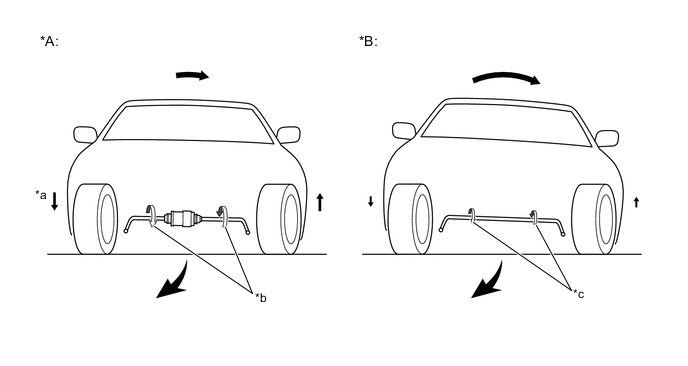
Text in Illustration (Vehicle Posture Image during Cornering) *A Models with Active Stabilizer Suspension System *B Models without Active Stabilizer Suspension System *a Movement of Vehicle Body Caused by Twisting of Active Stabilizer Actuator Assembly *b Twist of Stabilizer Bar Caused by Active Stabilizer Actuator Assembly Activation *c Reaction Force Proportional to Spring Constant of Stabilizer Bar - -
-
-
CONSTRUCTION
-
Active Stabilizer Control Actuator
-
The front and rear active stabilizer control actuator assemblies are located axially along the front and rear stabilizer bars.
-
The front and rear active stabilizer control actuator assemblies consist of components such as a motor and a reduction mechanism.
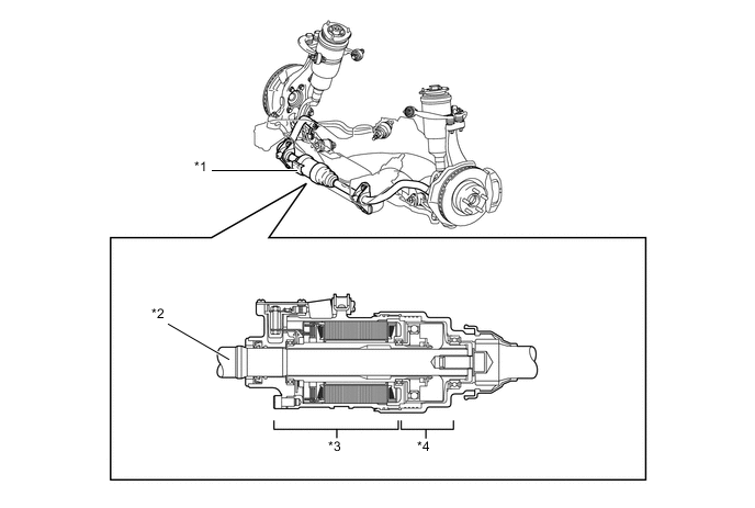
Text in Illustration (Front Active Stabilizer Control Actuator Assembly) *1 Front Active Stabilizer Control Actuator Assembly *2 Stabilizer Bar *3 Motor *4 Reduction Mechanism 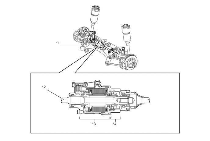
Text in Illustration (Rear Active Stabilizer Control Actuator Assembly) *1 Rear Active Stabilizer Control Actuator Assembly *2 Stabilizer Bar *3 Motor *4 Reduction Mechanism
-
-
Motor
-
A compact, high power output and low noise brushless type motor is used.
-
The motor shaft is coupled to the wave generator, and the motor housing is coupled to the circular gear.
-
The magnetic pole sensor (motor pulse sensor) detects the rotational angle of the motor shaft.
-
If a system malfunction occurs, the built-in motor short relay short circuits the motor terminals and virtually locks the active stabilizer control actuator assembly.
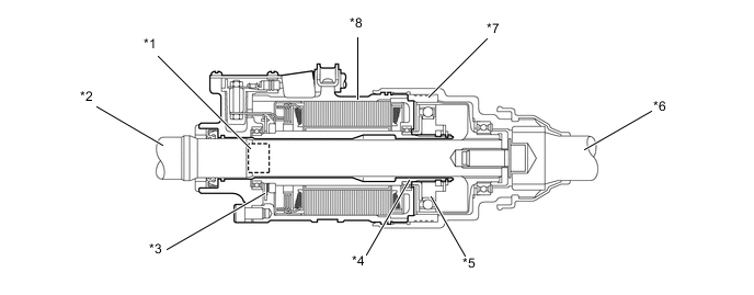
Text in Illustration *1 Motor Short Relay *2 Stabilizer Bar (RH Side) *3 Magnetic Pole Sensor (Motor Pulse Sensor) *4 Motor Shaft *5 Wave Generator *6 Stabilizer Bar (LH Side) *7 Circular Gear *8 Motor Housing
-
-
Reduction Mechanism
-
The reduction mechanism uses strain wave gearing, which is compact and highly accurate, and creates a large reduction gear ratio (1:200) using a small number of components.
-
The reduction mechanism consists of a wave generator, a flexible gear and a circular gear.
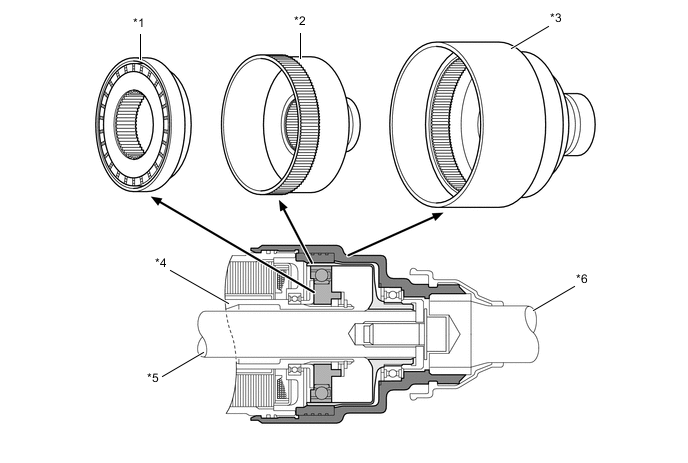
Text in Illustration *1 Wave Generator *2 Flexible Gear *3 Circular Gear *4 Motor Shaft *5 Stabilizer Bar (RH Side) *6 Stabilizer Bar (LH Side) Construction of Reduction Mechanism Item Construction Wave Generator (Input)
-
Consists of an oval-shaped cam, and a ball bearing that is fitted around the cam.
-
Coupled to the motor shaft of the motor, and rotates inside the flexible gear.
Flexible Gear (Output)
-
Consists of an elastic metal outer circumference that has 400 teeth and a spline coupled to the stabilizer bar (RH side).
-
Located on the outside of the wave generator, the flexible gear meshes with the circular gear while undergoing elastic deformation from the rotational movement of the wave generator.
Circular Gear (Output)
-
Consists of a housing inner circumference that has 402 teeth and a spline coupled to the stabilizer bar (LH side).
-
Located on the outside of the flexible gear, the circular gear meshes with the major axis of the flexible gear via the rotational movement of the wave generator.
-
-
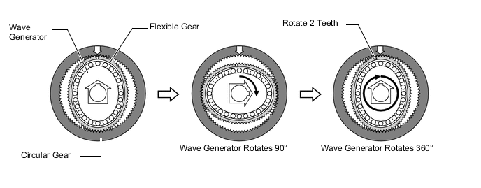
The flexible gear is fitted inside the circular gear. Furthermore, the wave generator is fitted inside the flexible gear. The rotational movement of the wave generator causes the flexible gear to become deformed into an oval shape. The teeth of the major axis mesh with the circular gear, and the teeth of the minor axis separate from the circular gear.
-
When the circular gear is fixed and the wave generator rotates clockwise, the flexible gear undergoes an elastic deformation. This results in the position of the meshing of the teeth being moved with the circular gear.
-
The flexible gear has 2 fewer teeth than the circular gear. Therefore, with each rotation of the wave generator, the flexible gear rotates 2 teeth counterclockwise, which is opposite to the rotational direction of the wave generator. This rotational difference is taken out as an output.
-
Due to the aforementioned principle, when the motor rotates clockwise, the rotational movement of the wave generator causes the flexible gear to rotate counterclockwise. This rotation causes a rotational difference between the stabilizer bar (RH side) coupled to the flexible gear and the stabilizer bar (LH side) coupled to the circular gear, thus changing the twist angle of the stabilizer bars.
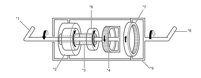
Text in Illustration *1 Stabilizer Bar (RH Side) *2 Motor *3 Motor Shaft *4 Flexible Gear *5 Motor Housing *6 Stabilizer Bar (LH Side) *7 Circular Gear *8 Wave Generator
-
-
-
FAIL-SAFE
-
If a system malfunction occurs, this function shorts the terminals of the motor in the active stabilizer control actuator assemblies. This generates a braking force that virtually locks the stabilizer bars (RH side and LH side), thus ensuring the same function as the conventional stabilizer bar.
-
-
DIAGNOSIS
-
If the front and rear active stabilizer control ECU assemblies detect a malfunction in the system, they illuminate the master warning light, indicate the warning message on the multi-information display, sound the multi buzzer to inform the driver and stop the system control.
-
The front and rear active stabilizer control ECU assemblies also store a Diagnostic Trouble Code (DTC). The DTC can be accessed through the use of a Global TechStream (GTS). For details, refer to the Repair Manual.
-