AIR SUSPENSION SYSTEM
-
FUNCTION OF MAIN COMPONENTS
Component Function Pneumatic Cylinder with Shock Absorber Assembly
-
Adjusts the vehicle height.
-
Changes the oil flow passage by rotating the rotary valve, and switches the damping force.
Absorber Control Actuator Changes the damping force of the shock absorber. No. 1 Height Control Valve Sub-assembly and No. 2 Height Control Valve Sub-assembly Supplies and discharges compressed air to and from the air chambers in the 4 pneumatic cylinders with shock absorber assemblies. No. 1 Height Control Compressor Motor Supplies compressed air to increase the vehicle height. Height Control Dryer Assembly Removes moisture from the compressed air. Height Control Exhaust Valve Discharges compressed air into the atmosphere from the pneumatic cylinder with shock absorber assemblies to lower the vehicle height. Height Control Sensor Sub-assembly Detects the vehicle height. Acceleration Sensor Detects the vertical acceleration rate of the body. Steering Sensor Detects the steering direction and the angle of the steering wheel. Yawrate Sensor
(with Built-in Deceleration Sensor)
Detects the vehicle's longitudinal and lateral acceleration and deceleration. Combination Switch Assembly Drive Mode Select Switches the driving mode. Height Control Switch Selects the vehicle height. Combination Meter Assembly Height Control Indicator Light Indicates the selected condition of the height control switch. Multi-information Display
-
Displays the selected condition of the drive mode select.
-
Displays a warning message when a system malfunction occurs.
Master Warning Light Illuminates when the warning message is displayed in the multi-information display. Suspension Control ECU (with Built-in Acceleration Sensor)
-
Estimates the condition of the vehicle in accordance with the signals provided by the sensors and switches, and outputs control signals to the No. 1 height control compressor and height control valves.
-
Estimates the condition of the vehicle in accordance with the signals provided by the sensors and switches, and outputs control signals to the absorber control actuators.
-
Detects the vertical acceleration rate of the body.
Hybrid Vehicle Control ECU Sends the motive force signal and drive torque signal to the suspension control ECU. Skid Control ECU Assembly
-
Sends the vehicle speed signal to the suspension control ECU.
-
Sends the brake pedal depressing signal to the suspension control ECU.
-
Makes a request for damping force control to the suspension control ECU.
Driving Support ECU Assembly* Makes a request for damping force control to the suspension control ECU. Main Body ECU (Driver Side Junction Block) Sends the door courtesy switches signals to the suspension control ECU.
-
*: Models with pre-crash safety system
-
-
SYSTEM CONTROL
-
The vehicle height control has the following functions:
Function Outline Automatic Leveling Function
-
Maintains vehicle height at a constant level regardless of the passenger and luggage weights.
-
Estimates the number of occupants and the amount of luggage in the vehicle when the door courtesy switch signal is input, and quickly actuates the vehicle height control.
High Speed Sensitive Function Lowers the vehicle height when the vehicle is driven at a prescribed speed or higher. This increases the vehicle aerodynamics and provides increased stability at high speeds. Vehicle Height Selection Function The driver can operate the height control switch to change the normal vehicle height position to the high vehicle height position as needed. -
-
The AVS effects the following controls:
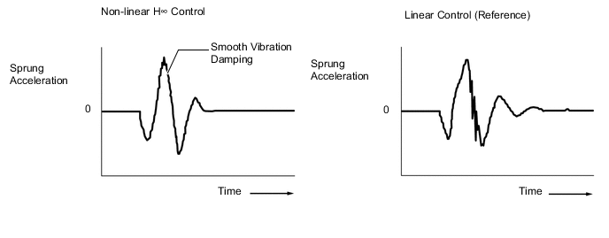
Control Outline Repercussion Control (Non-linear H∞ Control) Smoothly changes the damping force to a target value in accordance with the changes in the road surface or driving conditions. In this way, excellent ride comfort is achieved while ensuring a high level of vibration damping performance. Roll Posture Control Regulates the damping force to reduce the phase difference between the vehicle roll and pitch angles during steering, thus providing smooth superior maneuverability. Roughness Sensing Control Controls the shock absorber assemblies so that their damping force will not increase, when the road surface condition does not require a damping force. Unsprung Damping Control Controls so that the damping force will not decrease below a certain level, if unsprung resonance is detected in order to reduce the unsprung resonance. Anti-dive Control Makes the damping force firmer to restrain the body dive during braking, thus ensuring excellent stability and controllability. Anti-squat Control Makes the damping force firmer during acceleration to minimize the changes in the vehicle body posture. Vehicle Speed Sensing Control Controls damping force in accordance with vehicle speed, thus aiming for both riding comfort at a low speed and superior stability and controllability at a high speed. VSC Operation Control Changes the damping force to control the vehicle posture during VSC operation (front or rear skid). Pre-crash Safety System Operation Control* Switches damping force to the hard side in accordance with damping force control request signals from the driving support ECU assembly, and suppresses dive during braking. Damping Mode Selection The drive mode select enables the driver to select a desired damping force from the 3 modes.
-
*: Models with pre-crash safety system
-
-
Repercussion Control (Non-linear H ∞ Control)
-
In accordance with an acceleration sensor signal, the suspension control ECU detects vehicle vibrations (in the heave, roll and pitch directions) and controls the damping force of each of the 4 wheels using non-linear H∞ control logic. Therefore, vehicle repercussion is naturally and smoothly controlled, thus ensuring riding comfort.
-
-
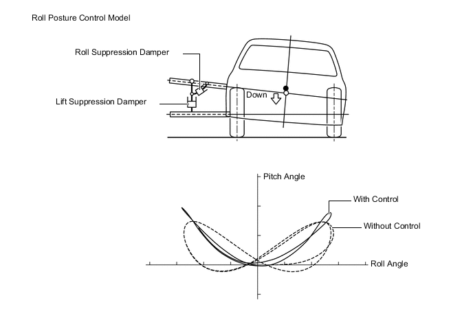
Roll Posture Control
-
In accordance with the steering sensor and yawrate sensor (deceleration sensor signal), the damping force of each wheel is controlled to optimize the vehicle posture condition while turning.
-
Using a roll posture control model, in which absorbers (for roll suppression and lift suppression) are located on the hypothetical inside turning point to control movement in 2 directions, damping force on the inside and outside turning sides is controlled with each of the 4 wheels independent. As a result, vehicle posture when turning is optimized, and groundholding performance is ensured.
-
Damping force is controlled to reduce the phase difference between the roll angle and pitch angle, thus achieving a vehicle posture compatible to the sensitivity of a human as well as comfortable steering.
-
-
Damping Mode Selection
-
The damping mode can be selected by operating the drive mode select.
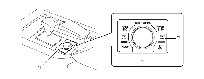
Text in Illustration *1 Combination Switch Assembly *2 Drive Mode Select *3 Height Control Switch - - -
The suspension control ECU changes the damping mode between COMFORT, NORMAL and SPORT in accordance with the selected drive mode.
-
When the damping mode is in SPORT, the damping force is set higher than when in NORMAL, thus achieving a setting appropriate for sporty driving.
-
When the damping mode is in COMFORT, the damping force is set lower than when in NORMAL, thus achieving a smooth and comfortable ride.
Drive Mode (Drive Mode Select Position) Damping Mode SPORT S+ SPORT SPORT S NORMAL NORMAL NORMAL COMFORT COMFORT ECO NORMAL 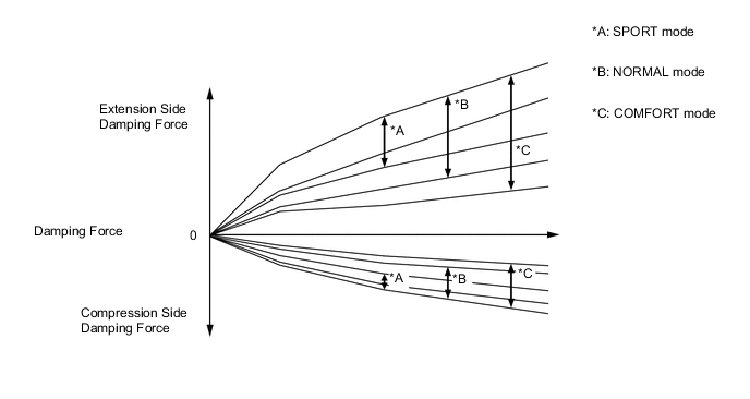
-
-
-
CONSTRUCTION
-
No. 1 Height Control Compressor
-
The No. 1 height control compressor has an integrated construction with a height control compressor with motor, which creates the compressed air necessary for raising the vehicle height; a height control dryer assembly which eliminates the moisture in the compressed air made by the height control compressor with motor; and a height control exhaust valve which drains the compressed air out to the atmosphere from the pneumatic cylinder with shock absorber assembly.
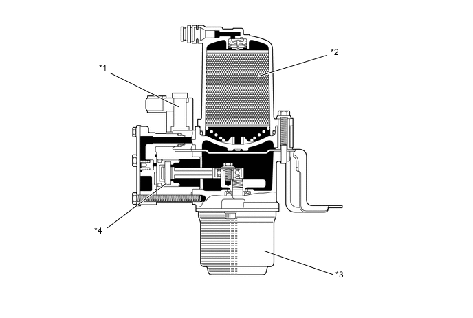
Text in Illustration *1 Height Control Exhaust Valve *2 Height Control Dryer Assembly *3 Motor *4 Height Control Compressor
-
-
Pneumatic Cylinder with Shock Absorber Assembly
-
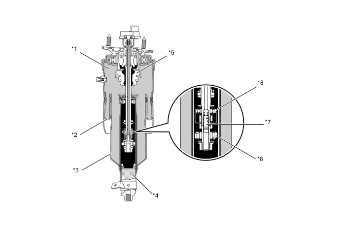
The pneumatic cylinder with shock absorber assembly consists of a single type air chamber with a large compressed air capacity in order to achieve excellent riding comfort.
-
A variable damping force mono-tube type shock absorber is used.
-
This shock absorber initiates the damping force in the infinitesimal speed range of the piston movement, achieving driving comfort and smooth and steady driving performance. In addition, by ensuring fully variable damping force to the shock absorber, excellent stability and ride comfort are achieved under any road surface conditions.
-
To switch the shock absorber's damping force, a hard damping valve and a soft damping valve have been provided. The damping force is varied by the rotary valve, which changes the ratio of oil that passes through the valve.
Text in Illustration (Front Pneumatic Cylinder with Shock Absorber) *1 Air Chamber *2 Diaphragm *3 Piston *4 High-pressure Nitrogen Gas *5 Bound Stopper *6 Hard Damping Valve *7 Rotary Valve *8 Soft Damping Valve 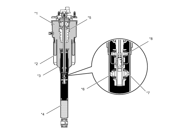
Text in Illustration (Rear Pneumatic Cylinder with Shock Absorber) *1 Air Chamber *2 Diaphragm *3 Piston *4 High-pressure Nitrogen Gas *5 Bound Stopper *6 Hard Damping Valve *7 Rotary Valve *8 Soft Damping Valve
-
-
Height Control Valve Sub-assembly
-
The height control valve sub-assemblies control the air passage between the No. 1 height control compressor and each pneumatic cylinder with shock absorber assembly.
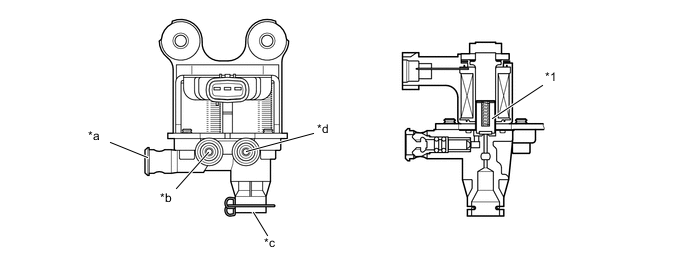
Text in Illustration (No. 1 Height Control Valve Sub-assembly) *1 Solenoid Valve - - *a Port (To No. 2 Height Control Valve Sub-assembly) *b Port (To Front Pneumatic Cylinder with Shock Absorber Assembly LH) *c Port (From No. 1 Height Control Compressor) *d Port (To Front Pneumatic Cylinder with Shock Absorber Assembly RH) 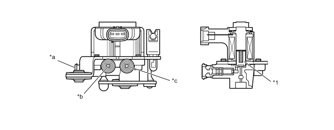
Text in Illustration (No. 2 Height Control Valve Sub-assembly) *1 Solenoid Valve - - *a Port (From No. 1 Height Control Valve Sub-assembly) *b Port (To Rear Pneumatic Cylinder with Shock Absorber Assembly LH) *c Port (To Rear Pneumatic Cylinder with Shock Absorber Assembly RH)) - -
-
-
Absorber Control Actuator
-
The absorber control actuator uses a step motor that switches in 9 steps to effect minute changes in the damping force.
-
The step motor consists of 2 sets of stators and coils.
-
To control the damping force, the step motor causes the magnetic rotor, which is directly coupled to the shock absorber control rod, to make small rotational movements in accordance with the signals received from the suspension control ECU.
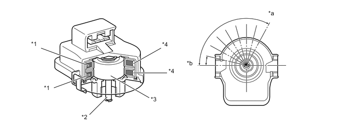
Text in Illustration *1 Coil *2 Output Shaft *3 Magnetic Rotor *4 Stator *a Soft *b Hard
-
-
Height Control Sensor Sub-assembly
-
The height control sensor sub-assembly detects the vehicle height.
-
The sensor has an arm that moves in accordance with the changes in vehicle height, and the resultant change in voltage enables the suspension control ECU to detect the vehicle height.
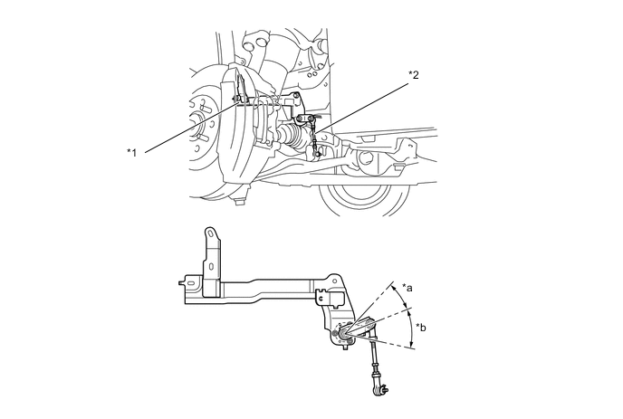
Text in Illustration (Front Height Control Sensor Sub-assembly) *1 Front Height Control Sensor Sub-assembly *2 Arm *a Bound *b Rebound 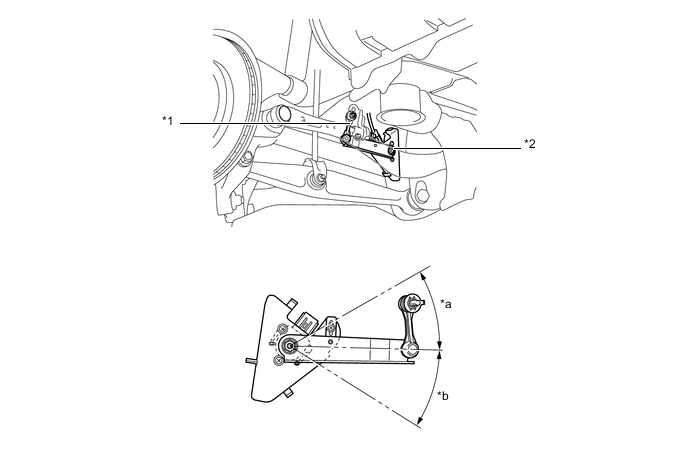
Text in Illustration (Rear Height Control Sensor Sub-assembly) *1 Arm *2 Rear Height Control Sensor Sub-assembly *a Bound *b Rebound
-
-
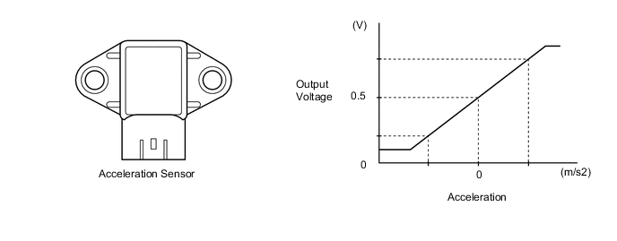
Acceleration Sensor
-
The acceleration sensor detects the vertical movement of the body.
-
3 acceleration sensors are provided. One of them is integrated in the suspension control ECU. The acceleration sensors independently detect the vertical acceleration rate.
-
-
Steering Sensor
-
The steering sensor detects the steering direction and angle.
-
2 pairs of magnetoresistive elements are provided in the actuator to detect rotation of the magnet built into the detection gear. The actuator detects magnetic resistance changes during detection gear rotation as the rotation of the steering wheel.
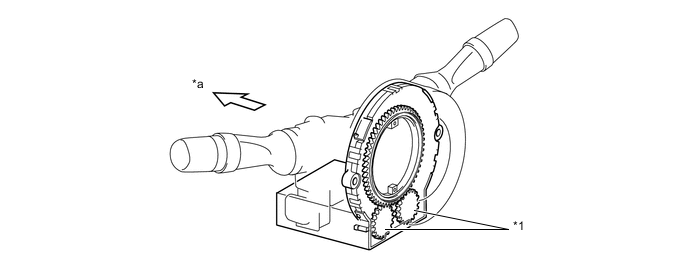
Text in Illustration *1 Detection Gear - - *a Front - -
-
-
Yawrate Sensor
-
The yawrate sensor and the deceleration sensor are integrated together for compactness and located in the lower portion of the center console.
-
The yawrate sensor detects capacitance changes caused by the vehicle's vertical axis rotation as a rotation angle speed.
-
The deceleration sensor detects capacitance changes between the movable electrode and fixed electrode as the vehicle's deceleration. 2 deceleration sensors, installed at 45-degree angles in the vehicle's front and rear direction, are used to enable the detection of the whole vehicle's deceleration in the horizontal direction.
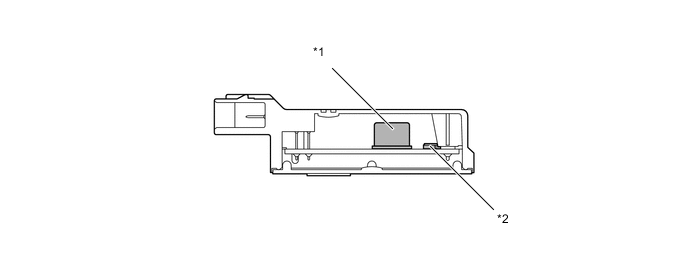
Text in Illustration *1 Yawrate Sensor *2 Deceleration Sensor
-
-
-
FAIL-SAFE
-
If a malfunction occurs in the air suspension system, the suspension control ECU prohibits the vehicle height control and damping force control.
-
-
DIAGNOSIS
-
If the suspension control ECU detects a malfunction in the air suspension system, it illuminates the master warning light and a warning message is displayed on the multi-information display to alert the driver of the malfunction.
-
The suspension control ECU will also store a Diagnostic Trouble Code (DTC). The DTC can be accessed through the use of a Global TechStream (GTS). For details, refer to the Repair Manual.
-