HYBRID TRANSMISSION SYSTEM
-
FUNCTION OF MAIN COMPONENTS
Component Function L110F Hybrid Transmission (Hybrid Vehicle Transmission Assembly) Motor Generator 1 (MG1)
-
Driven by the engine and generates high-voltage electricity in order to operate MG2 and/or to charge the HV battery. Also, MG1 functions as a starter to start the engine.
-
Operated to allow the gear ratio of the power split planetary gear unit to optimally suit the driving conditions of the vehicle.
Motor Generator 2 (MG2)
-
Driven by electrical power from MG1 and/or the HV battery, and generates motive force for the rear wheels.
-
Generates electricity to recharge the HV battery (regenerative braking) during braking or when the accelerator pedal is not depressed.
Resolvers
-
MG1 and MG2 are each equipped with a resolver.
-
Send information about the rotational speed and direction of the motor generators to the MG ECU.
Temperature Sensors for Motor Generator
-
MG1 and MG2 are each equipped with a temperature sensor.
-
Measure the temperature of MG1 and MG2.
Compound Gear Unit Power Split Planetary Gear Unit Distributes the engine motive force as appropriate to directly drive the vehicle as well as MG1. 2-stage Motor Speed Reduction Planetary Gear Unit Reduces the rotational speed of MG2 in accordance with the characteristics of the planetary gear in order to increase torque. Furthermore, it shifts the transmission in 2 stages in accordance with the conditions of the vehicle. Valve Body Unit Solenoid Valves SL1/SL2 Switch low-speed range and high-speed range. Solenoid Valve SP Controls line pressure. Oil Pressure Switches Detect the oil pressure in the oil pressure control circuit. ATF Temperature Sensor Detects the ATF temperature. Mechanical Oil Pump Driven by engine power, supplies oil pressure to the valve body unit and lubricates the planetary gear. Transmission Revolution Sensor Detects the output speed of the transmission. Shift Lever Position Sensor Converts the shift lever position into electrical signals and outputs the signals to the hybrid vehicle control ECU. Oil Pump with Motor Assembly Supplies oil pressure to the valve body unit and lubricates the planetary gear mainly when the engine is stopped. Oil Pump Motor Controller Drives the oil pump with motor assembly in accordance with a signal from the hybrid vehicle control ECU to variably regulate the ATF discharge amount. Inverter with Converter Assembly Inverter Converts high-voltage DC (HV battery) into AC (MG1 and MG2) and vice versa (converts AC into DC). Boost Converter Boosts the voltage of the HV battery from DC 288 V to a maximum of DC 650 V and vice versa (drops from DC 650 V to DC 288 V). Motor Generator ECU (MG ECU) Controls the inverter and boost converter in accordance with signals received from the hybrid vehicle control ECU, thus operating MG1 or MG2 as either a generator or motor. Inverter Current Sensors
-
MG1 and MG2 are each provided with 2 inverter current sensors.
-
Measure the current of MG1 and MG2.
Inverter Temperature Sensors
-
Provided for the boost converter, Intelligent Power Module (IPM) for MG1 and MG2, and inverter coolant.
-
Measure the temperature of the boost converter, IPM for MG1 and MG2, and inverter coolant.
Atmospheric Pressure Sensor Detects the atmospheric pressure. HV Battery Assembly Battery Voltage Sensor
-
Monitors voltage signals from the battery cooling blower assembly and conditions of the HV battery such as voltage, temperature and current, and transmits this information to the hybrid vehicle control ECU.
-
Monitors the high voltage system for breakdown of the electrical insulation.
Speed Sensors Detect the wheel speed of each of the 4 wheels. Accelerator Pedal Position Sensor Converts the accelerator pedal position into an electrical signal and outputs the signal to the hybrid vehicle control ECU. Shift Paddle Switch (Transmission Shift Switch Assembly)* Detects the driver's shift-up and shift-down operations. Transmission Control Switch
-
Detects that the shift lever is in S.
-
Detects the driver's shift-up and shift-down operations when the shift lever is in S.
Combination Switch Assembly Drive Mode Select Outputs the drive mode (NORMAL, ECO, COMFORT or SPORT S/S+) signal to the various ECUs via the driver side switch module when operated by the driver. SNOW Mode Switch Outputs the SNOW mode switch signal to the hybrid vehicle control ECU via the ECM when operated by the driver. Hybrid Vehicle Control ECU
-
Performs comprehensive control of the hybrid system. This includes the electric continuously variable transmission and HV battery.
-
Receives information from various sensors as well as from ECUs (ECM, battery voltage sensor, MG ECU and skid control ECU), calculates the required torque and output power based on this and sends the calculated result to the ECM, MG ECU and skid control ECU.
-
Monitors the SOC of the HV battery.
-
Controls the oil pump with motor assembly.
-
Controls the hybrid vehicle converter.
-
Controls the inverter water pump with motor assembly.
-
Controls the battery cooling blower assemblies.
-
Controls the power steering converter assembly.
ECM
-
Controls the engine in accordance with the target engine speed and required engine motive force received from the hybrid vehicle control ECU.
-
Transmits the operating condition signals of the engine to the hybrid vehicle control ECU.
Combination Meter Assembly SNOW Mode Indicator Light Informs the driver that the SNOW mode is entered. Multi-information Display
-
Displays the shift lever position.
-
Displays the shift range.
-
Displays the energy flow.
-
Displays the drive mode.
-
Displays messages to inform the driver when a malfunction occurs.
-
Shows system status and appropriate operations to be performed.
Meter Panel Illumination Illuminates in blue or red in response to drive mode. Also, the brightness level changes when illuminated in blue in accordance with driving conditions.
-
*: Models with shift paddle
-
-
SYSTEM CONTROL
Electronic Control of Hybrid Transmission Control Function Clutch to Clutch Pressure Control Controls the pressure that is applied directly to B1and B2brakes by actuating the solenoid valves SL1 and SL2 in accordance with the hybrid vehicle control ECU signals.
Line Pressure Control Actuates the solenoid valve SP to control the line pressure in accordance with information from the hybrid vehicle control ECU and the operating conditions of the transmission.
-
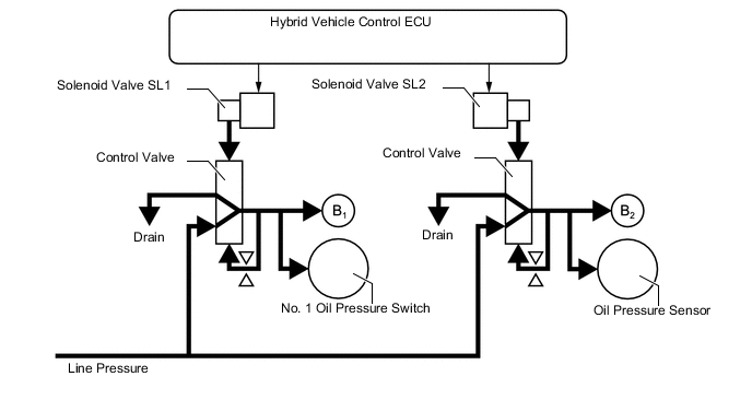
Clutch to Clutch Pressure Control
-
This control regulates the 2-stage motor speed reduction planetary gear unit switching to the low-speed range or high-speed range without using a 1-way clutch.
-
Solenoid valves SL1 and SL2 are operated by the drive current from the hybrid vehicle control ECU. The output pressure of these solenoids is adjusted by the control valve to regulate the brake engagement oil pressure that makes a connection between the No. 1 brake (B1) and No. 2 brake (B2).
-
The hybrid vehicle control ECU independently controls solenoid valves SL1 and SL2 using optimal oil pressure and timing according to information such as vehicle speed, driver's required motive force, etc. which is based on signals from each sensor, thus outputting MG2 as continuous motive force from start-up to driving at maximum vehicle speed.
-
-
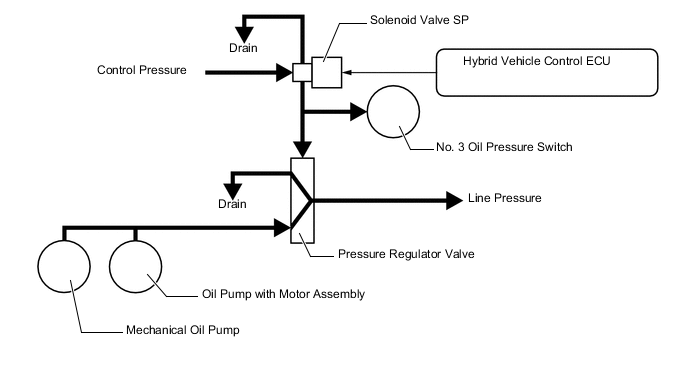
Line Pressure Control
-
This control regulates line pressure using the solenoid valve SP. High oil pressure control is conducted when switching between the low-speed range and high-speed range and when driving under high load, and low oil pressure control is conducted when driving under low load, thus aiming for improved fuel efficiency.
-
-
-
FUNCTION
-
Sequential Shiftmatic System
-
The sequential shiftmatic system enables the driver to select 8 stages of engine braking forces by operating the shift paddle* or shift lever. By controlling the engine, MG1 and MG2, this system improves the generation response of the engine braking force and acceleration response. In addition, a shift range which is lower than NORMAL mode can be selected in SPORT S/S+ mode, thus making it possible to obtain a greater engine braking force.
-
*: Models with shift paddle
-
-
By moving the shift lever to S, the automatic shifting mode will be switched to shift range selecting mode. By operating the shift paddle*1 or shift lever, driving in the shift range selected by the driver is possible, and the accelerator pedal characteristics and acceleration response can be selected.*2 In the low shift range, motive force in the intermediate area of accelerator opening has been increased, thus improving the vehicle response to the driver's operation. In the high shift range, motive force changes in accordance with accelerator operation amount changes have been decreased more than normal, thus enhancing accelerator control making it easy to maintain the vehicle speed during constant-speed cruising.
Tech Tips
*1: Models with shift paddle
*2: This does not indicate that maximum vehicle speed and maximum motion performance have been improved. Also, when the shift lever is moved to S, accelerator characteristics in SPORT S/S+ mode, ECO mode and SNOW mode are disabled.
-
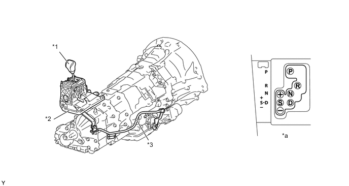
On models with shift paddle, when the shift lever is in D, the system changes to a momentary shift range selecting mode by performing a "-" (downshift) operation with the shift paddle. By operating the shift paddle in the same way as when in S, shift range selection is possible even in D. As a result, engine braking forces can be selected by operating the shift paddle without the need to remove hands from the steering wheel while driving.
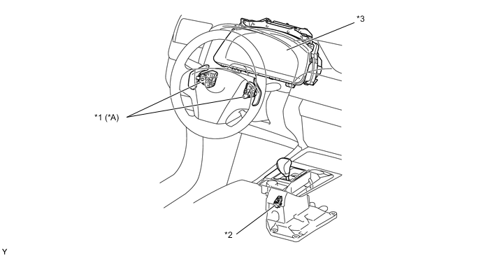
Text in Illustration *A Models with Shift Paddle - - *1 Shift Paddle Switch (Transmission Shift Switch Assembly) *2 Transmission Control Switch *3 Combination Meter Assembly
- Multi-information Display
- Multi Buzzer
- - -
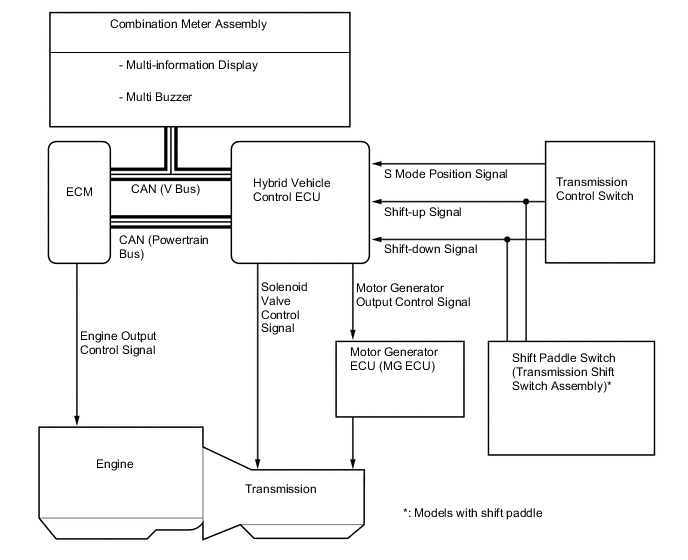
An S mode position signal is output from the transmission control switch to the hybrid vehicle control ECU when the shift lever is moved from D to S, and then the system switches to shift range selecting mode, which enables shift range switching operation using the shift paddle* or shift lever.
-
*: Models with shift paddle
-
-
On models with shift paddle, by performing a "-" (downshift) operation with the shift paddle when driving with the shift lever in D, a shift-down signal is output from the shift paddle switch (transmission shift switch assembly) to the hybrid vehicle control ECU, and the system switches to the momentary shift range selecting mode, which makes it possible to perform shift range selection with the shift paddle even in D.
-
In shift range selecting mode, by performing a "+" (upshift) or "-" (downshift) operation using the shift paddle* or shift lever, a shift-up signal or shift-down signal is output from the shift paddle switch (transmission shift switch assembly)* or transmission control switch to the hybrid vehicle control ECU, and the shift range is changed. While using the selected shift range as the upper limit, an optimal shift point is automatically selected in accordance with driving conditions.
-
*: Models with shift paddle
-
-
Holding the shift lever to "+" (upshift) in S will change the shift range to the S8 range regardless of current shift range (S1 to S7).
-
In order to protect the transmission, when accelerating while any range between S1 range and S5 range is selected in shift range selecting mode, sequential upshifts are automatically performed up to S6 range by exceeding the reject vehicle speed in each shift range.
-
The shift range position is displayed on the multi-information display in the combination meter assembly to inform the driver of shift range selection conditions.
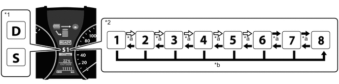
Text in Illustration *1 Shift Position Display *2 Shift Range Position Display *a Conducting "+" (Upshift) or "-" (Downshift) Operation *b Holding Shift Lever to "+" (Upshift) 
Manual Operation 
Manual and Automatic Operation -
On models with shift paddle, the momentary shift range selecting mode with the shift lever in D is canceled in the following conditions:
-
The "+" (upshift) side shift paddle has been operated for a certain period of time.
-
The "+" (upshift) side shift paddle is operated in D7 range.
-
The accelerator pedal has been continuously depressed for a certain period of time in the same range.
-
The vehicle has stopped.
-
The shift lever is moved to any position other than D.*
Tech Tips
*: When the shift lever is moved to S, the system changes to the S position shift range selecting mode.
-
-
Upon receiving a downshifting request issued by the driver through the operation of the shift paddle* or shift lever, this system limits the switching of the shift range if the vehicle is running at a speed that is higher than the limit speed, and informs the driver by sounding an alarm.
-
*: Models with shift paddle
Downshifting Request Limit Speed 8 → 7 - 7 → 6 225 km/h (140 mph) 6 → 5 180 km/h (112 mph) 5 → 4 142 km/h (88 mph) 4 → 3 104 km/h (65 mph) 3 → 2 89 km/h (55 mph) 2 → 1 66 km/h (41 mph) -
-
-
Shift Lock System
-
The shift lock system prevents the shift lever from being moved to any position other than P, unless the power switch is turned on (IG) and the brake pedal is depressed. This prevents the vehicle from starting off suddenly.
-
The shift lock system is controlled by the shift lock control ECU sub-assembly and it has a shift lock function.
-
The shift lock control ECU sub-assembly uses the P detection switch to detect the shift lever position, and receives input signals from the stop light switch assembly and power switch. Upon receiving these signals, the shift lock control ECU sub-assembly turns on the shift lock solenoid in order to release the shift lock.
-
A shift lock release button, which manually overrides the shift lock mechanism, is used.
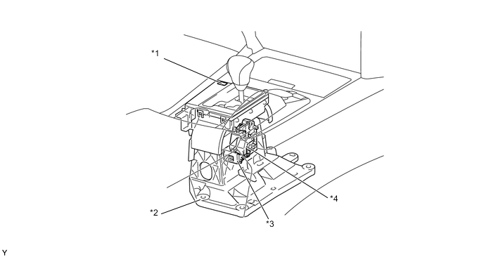
Text in Illustration *1 Shift Lock Release Button *2 Transmission Floor Shift Assembly *3 Shift Lock Control ECU Sub-assembly *4 Shift Lock Solenoid Assembly
- P Detection Switch

-
-
-
CONSTRUCTION
-
L110F Hybrid Transmission (Hybrid Vehicle Transmission Assembly)
-
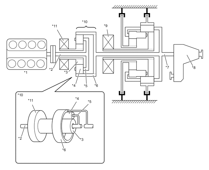
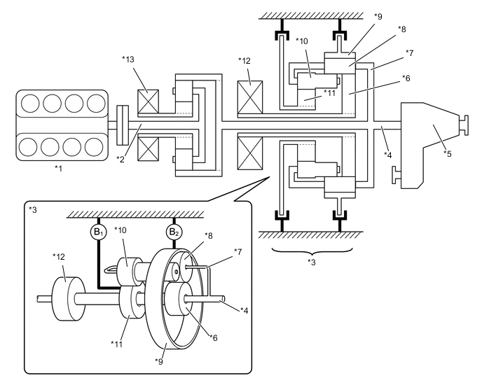
This transmission consists of the following components: a Motor Generator 1 (MG1) that operates primarily as a generator, a Motor Generator 2 (MG2) that operates primarily for driving the vehicle, a power split planetary gear unit that splits the engine motive force between the MG1 and the wheels, a 2-stage motor speed reduction planetary gear unit that operates as a reduction mechanism for the MG2, a valve body unit that controls hydraulic pressure, a mechanical oil pump that is driven by the engine, an electrical oil pump that supplies hydraulic pressure when the engine is stopped, and a transmission damper.
-
The MG1, MG2, power split planetary gear unit, and 2-stage motor speed reduction planetary gear unit are located axially along the engine output shaft.
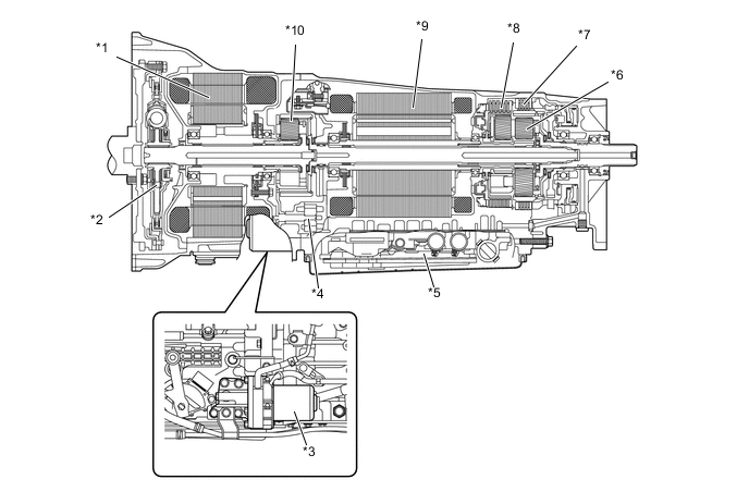
Text in Illustration *1 Motor Generator 1 (MG1) *2 Transmission Damper *3 Electrical Oil Pump *4 Mechanical Oil Pump *5 Valve Body Unit *6 2-stage Motor Speed Reduction Planetary Gear Unit *7 No. 2 Brake (B2)
*8 No. 1 Brake (B1)
*9 Motor Generator 2 (MG2) *10 Power Split Planetary Gear Unit
-
-
Compound Gear Unit
-
A power split planetary gear unit and a 2-stage motor speed reduction planetary gear unit are provided.
-
The power split planetary gear unit consists of a sun gear, pinion gear and ring gear. The power split planetary gear unit splits the motive force of the engine into 2 ways: one to drive the wheels, and the other to drive the MG1, so that it can function as a generator.
-
The 2-stage motor speed reduction planetary gear unit consists of a front sun gear, rear sun gear, long pinion gear, short pinion gear and ring gear. The motive force of the MG2 is transmitted via the rear sun gear to the carrier, in order to drive the wheels.
-
The power split planetary gear unit is located behind the MG1, and the 2-stage motor speed reduction planetary gear unit is located behind the MG2. They are connected as follows:
Item Connection Power Split Planetary Gear Unit Sun Gear MG1 Carrier Input Shaft Ring Gear Output Shaft (Transfer) 2-stage Motor Speed Reduction Planetary Gear Unit Front Sun Gear No. 1 Brake (B1)
Rear Sun Gear Long Pinion Gear (MG2) Carrier Output Shaft (Transfer) Ring Gear No. 2 Brake (B2)
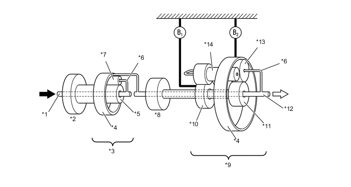
Text in Illustration *1 Input Shaft *2 MG1 *3 Power Split Planetary Gear Unit *4 Ring Gear *5 Sun Gear *6 Carrier *7 Pinion Gear *8 MG2 *9 2-stage Motor Speed Reduction Planetary Gear Unit *10 Front Sun Gear *11 Rear Sun Gear *12 Output Shaft *13 Short Pinion Gear *14 Long Pinion Gear From Engine To Transfer
-
-
Power Split Planetary Gear Unit
-
The power split planetary gear unit splits the motive force of the engine into the force used for driving the wheels and the force used for driving the MG1 to function as a generator. In addition, the motive force of the MG1 is used for starting the engine.
-
As part of the power split planetary gear unit, the sun gear is connected to MG1, the ring gear is connected to the output shaft and the carrier is connected to the input shaft.
Text in Illustration *1 Engine *2 Input Shaft *3 Sun Gear *4 Pinion Gear *5 Carrier *6 Ring Gear *7 Output Shaft *8 Transfer *9 MG2 *10 Power Split Planetary Gear Unit *11 MG1 - - -
The motive force of the power split planetary gear unit is transmitted as follows:
-
Transmission of Engine Motive Force to Wheels
The engine motive force, which is input by the carrier, is output to the ring gear. Thus, the motive force is transmitted in order to drive the wheels.
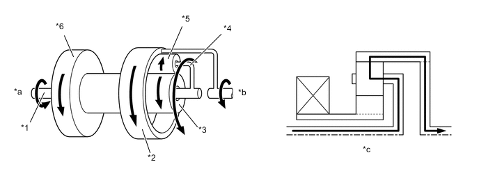
Text in Illustration *1 Input Shaft *2 Ring Gear *3 Sun Gear *4 Carrier *5 Pinion Gear *6 MG1 *a From Engine *b Drive Wheels *c Transmission Image - - -
Transmission of Engine Motive Force to MG1
The engine motive force, which is input by the carrier, is output to the sun gear. Thus, the motive force is transmitted in order to operate MG1 as a generator.
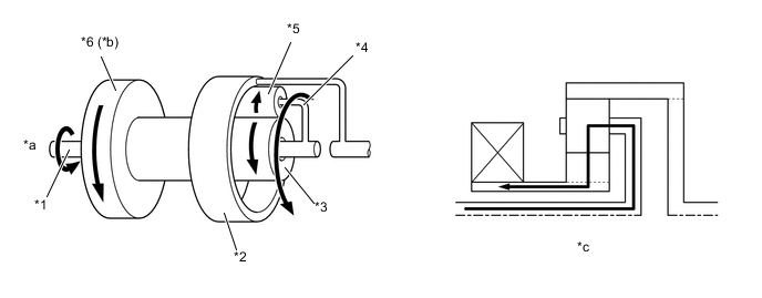
Text in Illustration *1 Input Shaft *2 Ring Gear *3 Sun Gear *4 Carrier *5 Pinion Gear *6 MG1 *a From Engine *b Generates Electricity *c Transmission Image - - -
Transmission of MG1 Motive Force for Starting Engine
The MG1 motive force is input by the sun gear and output to the carrier. Thus, the motive force is transmitted in order to start the engine.
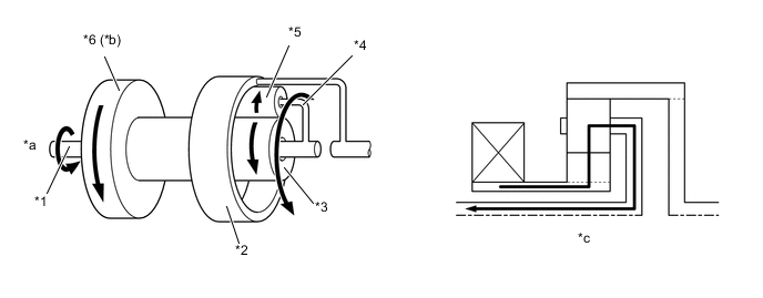
Text in Illustration *1 Input Shaft *2 Ring Gear *3 Sun Gear *4 Carrier *5 Pinion Gear *6 MG1 *a Starting Engine *b Drive *c Transmission Image - -
-
-
-
2-stage Motor Speed Reduction Planetary Gear Unit
-
The 2-stage motor speed reduction planetary gear unit controls the MG2 motor speed in 2 stages between the low-speed range and the high-speed range, ensuring both maximum motive force and maximum speed.
-
A No. 1 brake (B1) and a No. 2 brake (B2), which are applied under hydraulic control, have been provided. When the No. 1 brake (B1) is applied, it fixes the front sun gear, and when the No. 2 brake (B2) is applied, it fixes the ring gear. As a result, the unit switches the reduction ratio of the MG2 motor speed between the low-speed range and high-speed range in accordance with the vehicle speed and the accelerator opening.
-
The No. 2 brake (B2) uses double pistons to reduce the hydraulic pressure and make the pistons more compact.
Text in Illustration *1 Engine *2 Input Shaft *3 2-stage Motor Speed Reduction Planetary Gear Unit *4 Output Shaft *5 Transfer *6 Rear Sun Gear *7 Carrier *8 Short Pinion Gear *9 Ring Gear *10 Long Pinion Gear *11 Front Sun Gear *12 MG2 *13 MG1 - - -
The motive force of the MG2 is transmitted from the rear sun gear that is connected to the MG2 to the short pinion gear. The short pinion gear engages with the ring gear that is fixed by the No. 2 brake, rotates on its axes and revolves inside the ring gear. Thus, the motive force is transmitted to the wheels via the carrier.
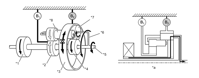
Text in Illustration (Low-speed Range Power Flow) *1 MG2 *2 Front Sun Gear *3 Ring Gear *4 Rear Sun Gear *5 Output Shaft *6 Carrier *7 Short Pinion Gear *8 Long Pinion Gear *a Transmission Image - - -
The motive force of the MG2 is transmitted from the rear sun gear that is connected to the MG2 via the short pinion gear to the long pinion gear. The long pinion gear engages with the front sun gear that is fixed by the No. 1 brake, rotates on its axes and revolves around the front sun gear. Thus, the motive force is transmitted to the wheels via the carrier.
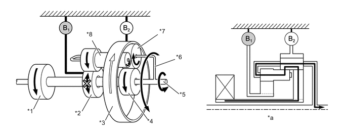
Text in Illustration (High-speed Range Power Flow) *1 MG2 *2 Front Sun Gear *3 Ring Gear *4 Rear Sun Gear *5 Output Shaft *6 Carrier *7 Short Pinion Gear *8 Long Pinion Gear *a Transmission Image - -
-
-
Valve Body Unit
-
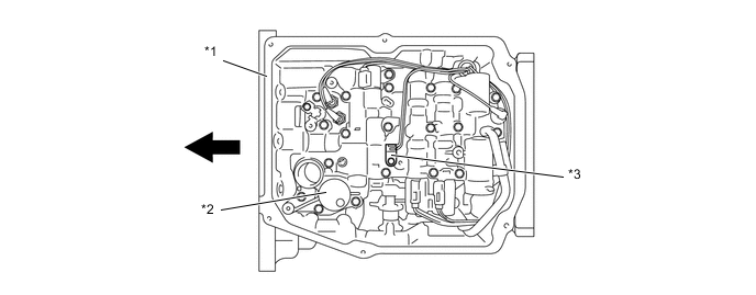
The upper valve body has been integrated in the transmission case, and is located in the oil pan.
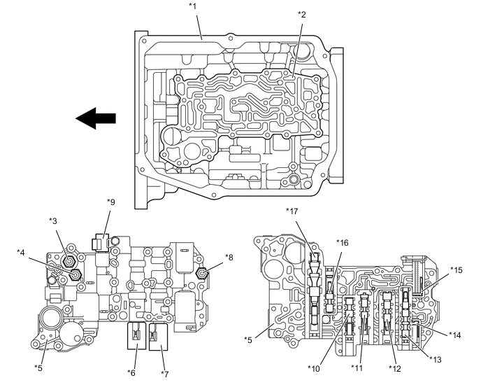
Text in Illustration *1 Transmission Case *2 Upper Valve Body *3 No. 2 Oil Pressure Switch *4 No. 3 Oil Pressure Switch *5 Lower Valve Body *6 Solenoid Valve SL1 *7 Solenoid Valve SL2 *8 No. 1 Oil Pressure Switch *9 Upper Valve Body *10 B1Apply Control Valve
*11 B1Control Valve
*12 B2Control Valve
*13 B2Apply Control Valve
*14 B2Damper
*15 B1Accumulator Valve
*16 Modulator Valve *17 Pressure Regulator Valve - - Front - -
-
-
Solenoid Valves SL1 and SL2
-
The solenoid valves SL1 and SL2 are actuated in accordance with the signal from the hybrid vehicle control ECU, and this output pressure is directly guided to the control valves B1and B2in order to regulate the line pressure that acts on the No. 1 brake (B1) and No. 2 brake (B2). As a result, high response and excellent shift characteristics have been achieved.
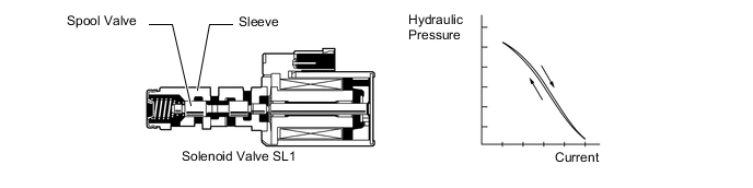
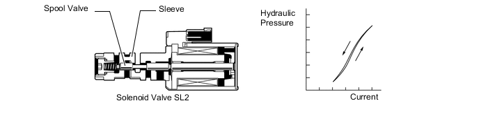
Function of Solenoid Valves SL1 and SL2 Item Function Solenoid Valve SL1 No. 1 brake (B1) pressure control
Solenoid Valve SL2 No. 2 brake (B2) pressure control
Operating of Solenoid Valves SL1 and SL2 Shift Lever Position Solenoid Valve Brake SL1 SL2 B1
B2
P Power Source Mode is Off Off Off X X Power Source Mode is On (Ready) Off On X ○ R Off On X ○ N Off On X ○ D, S Low-speed Range Off On X ○ High-speed Range On Off ○ X Tech Tips
○: Operates
X: Does not operate
-
-
Solenoid Valve SP
-
This solenoid valve uses a 3-way solenoid valve to control the line pressure. It effects high pressure control to switch the 2-stage motor speed reduction planetary gear unit between the low-speed range and high-speed range. It effects low pressure control during low load cruising, in order to improve fuel economy.
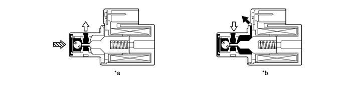
Text in Illustration *a Off Condition *b On Condition Drain Control Pressure 
Line Pressure - - Function of Solenoid Valve SP Item Function Solenoid Valve SP Line pressure control
-
-
Oil Pressure Switch
-
Oil pressure switches for oil pressure detection when shifting are installed in the lower valve body.
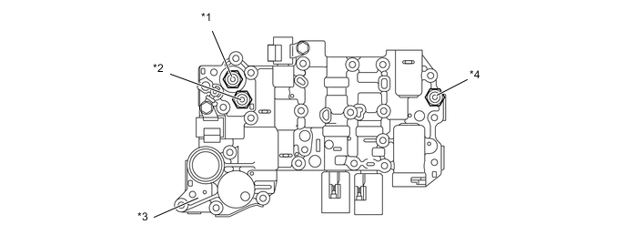
Text in Illustration *1 No. 2 Oil Pressure Switch *2 No. 3 Oil Pressure Switch *3 Lower Valve Body *4 No. 1 Oil Pressure Switch Function of Oil Pressure Switches Item Function No. 1 Oil Pressure Switch Detects hydraulic pressure of No. 1 brake (B1) and inputs it into hybrid vehicle control ECU.
No. 2 Oil Pressure Switch Detects hydraulic pressure of No. 2 brake (B2) and inputs it into hybrid vehicle control ECU.
No. 3 Oil Pressure Switch Detects line pressure and inputs it into hybrid vehicle control ECU. -
The hybrid vehicle control ECU detects the states after line pressure control by way of the oil pressure switches. The following table indicates the normal states of the oil pressure switches:
Operating of Oil Pressure Switches 2-stage Motor Speed Reduction Planetary Gear Unit Range Line Pressure No. 1 Oil Pressure Switch No. 2 Oil Pressure Switch No. 3 Oil Pressure Switch Low-speed Range High Off On Off Low Off Off Off High-speed Range High On Off On Low Off Off Off
-
-
ATF Temperature Sensor
-
The ATF temperature sensor is provided in the lower valve body. The hybrid vehicle control ECU detects the ATF temperature via this sensor in order to make corrections to the line pressure control.
Text in Illustration *1 Transmission Case *2 Lower Valve Body *3 ATF Temperature Sensor - - Front - -
-
-
Lubrication Mechanism
-
In addition to the mechanical oil pump that is driven by the engine, an electrical oil pump that supplies hydraulic pressure when the engine is stopped is provided on the right side of the transmission. This ensures the proper hydraulic pressure control function when the engine is stopped. At the same time, the 2 oil pumps coordinate to provide the required discharge volume in order to optimize the discharge volume.
-
Mounting the oil cooler inside the radiator ensures the cooling performance of the transmission. An oil cooler tube and hose are used for connection between the transmission and oil cooler. As a result, ATF can be filled from the outlet hose, simplifying the service procedure.
-
The ATF WS is used to reduce the resistance of the ATF and improve fuel economy by reducing its viscosity in the practical operating temperature range.
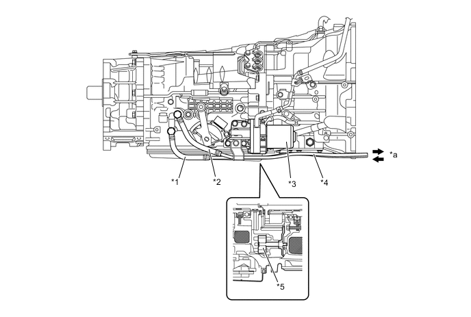
Text in Illustration *1 Inlet Hose *2 Outlet Hose *3 Oil Pump with Motor Assembly *4 Oil Cooler Tube *5 Mechanical Oil Pump - - *a Oil Cooler - - -
The electrical pump uses a brushless motor and its sensing portion contains a rotation speed sensor that uses a Hall IC. Upon receiving signals from the hybrid vehicle control ECU, the oil pump motor controller calculates the motor rotation speed and changes the motor rotation speed in order to control the discharge volume of the pump. Also, the pump contains a motor coil temperature sensor, which detects the motor coil temperature at the discharge area and transmits the information to the hybrid vehicle control ECU.
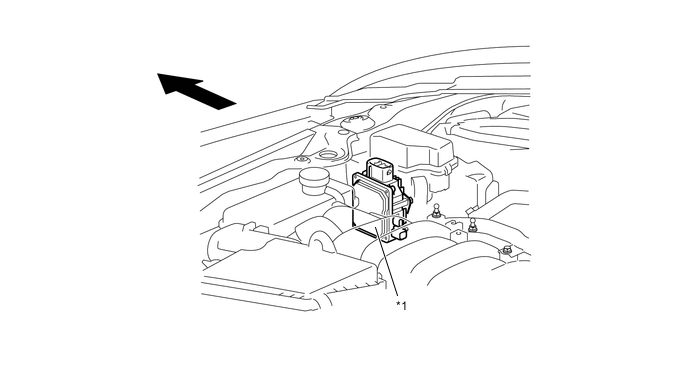
Text in Illustration *1 Oil Pump Motor Controller - - Front - - 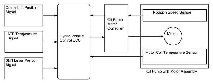
-
-
ATF Filling Procedures
-
ATF filling procedures used for the L110F hybrid transmission do not require an oil filler tube and oil level gauge. This ensures the accuracy of the ATF level after the transmission is repaired or replaced.
-
This filling procedure employs an outlet hose, overflow plug, ATF temperature sensor, and shift indicator "D" on the multi-information display. After refilling the transmission with ATF, remove the overflow plug at the proper ATF temperature to drain the extra ATF, in order to attain the appropriate ATF level.
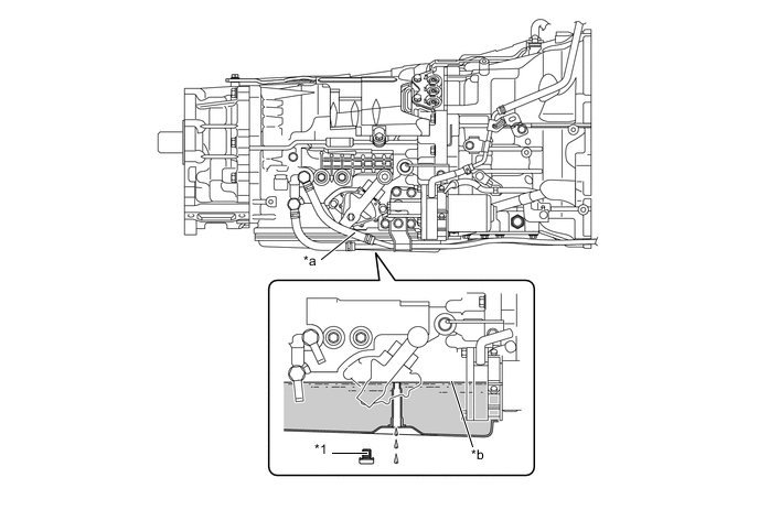
Text in Illustration *1 Overflow Plug - - *a ATF Filling Location (to Disconnect Outlet Hose) *b Proper Level 
ATF - -
-
-
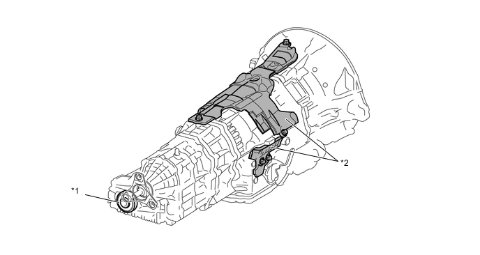
Transmission Revolution Sensor
-
The transmission revolution sensor detects the speed of the output shaft. The parking lock gear is used as the timing rotor for this sensor.
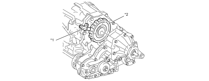
Text in Illustration *1 Transmission Revolution Sensor *2 Sensor Rotor (Parking Lock Gear)
-
-
Parking Lock Mechanism
-
The parking lock mechanism consists of a parking lock pawl and a parking lock gear which is integrated with the compound gear.
Text in Illustration *1 Transmission Control Shaft Lever *2 Parking Lock Lever *3 Parking Lock Rod *4 Parking Lock Pawl *5 Floor Shift Gear Shifting Rod Sub-assembly *6 Parking Lock Gear
-
-
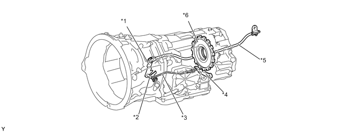
Transmission Damper
-
A coil spring type transmission damper is used.
-
A torque fluctuation absorbing mechanism that uses the dry-type, single-plate friction material absorbs the torque fluctuation in the motive force of the engine. Furthermore, the 2-stage hysteresis portion dampens the fluctuation of the engine rotation in order to reduce the shock when the engine starts.
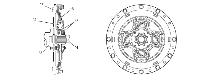
Text in Illustration *1 Flywheel Portion *2 Coil Spring *3 Crankshaft (Engine) *4 Input Shaft (Transmission) *5 2-stage Hysteresis Portion *6 Torque Fluctuation Absorbing Mechanism
-
-
Sound Absorption Cover and Dynamic Damper
-
The sound absorption covers installed on the outside of the transmission reduce transmission noise.
-
The dynamic damper installed on the rear end of the transfer reduces transmission noise.
Text in Illustration *1 Dynamic Damper *2 Sound Absorption Cover
-
-
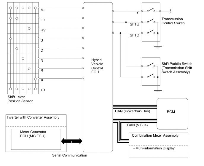
Shift Lever Position Sensor, Transmission Control Switch and Shift Paddle Switch (Transmission Shift Switch Assembly)
-
The shift lever position sensor sends the P, R, N, D and NSW signals to the hybrid vehicle control ECU. The hybrid vehicle control ECU also sends signals to the shift position indicator P, R, N and D in the combination meter assembly via CAN.
-
The transmission control switch is installed inside the transmission floor shift assembly to detect the S mode position and to inform the hybrid vehicle control ECU. The hybrid vehicle control ECU turns on the S mode indicator in the combination meter assembly.
-
The transmission control switch detects whether the shift lever is in S, and detects whether the shift lever is moved to "+" (upshift) or "-" (downshift) when the S mode is selected, and sends signals to the hybrid vehicle control ECU. At this time, the hybrid vehicle control ECU turns on the shift range indicator in the combination meter assembly via CAN for the selected shift range.
-
On the models with shift paddle, the shift paddle switch (transmission shift switch assembly) is installed in the steering wheel. The hybrid vehicle control ECU detects the operation of the shift paddle is "+" (upshift) or "-" (downshift) when the shift lever is in D or S.
-
-
Shift Control Mechanism
-
A gate type shift lever that uses a transmission control rod is used.
-
The shift control mechanism consists of a transmission floor shift assembly, a shift lever knob and a floor shift gear shifting rod sub-assembly.
Text in Illustration *1 Shift Lever Knob *2 Transmission Floor Shift Assembly *3 Floor Shift Gear Shifting Rod Sub-assembly - - *a Shift Pattern - -
-
-
-
OPERATION
-
Power Split Planetary Gear Unit
-
The relationship between the rotational direction and the torque that acts on the gears is described through the following main operation examples:
-
Starting Off
-
Running with MG2 and Engine
-
During Low Load and Constant-speed Cruising
-
During Full Throttle Acceleration
-
During Deceleration
-
Driving in Reverse
-
-
-
How to Read Nomographic Chart
-
The nomographic chart below gives a visual representation of the planetary gear's rotational direction, rotational speed and torque balance. In the nomographic chart, the rpm of the 3 gears in the power split planetary gear unit maintain a relationship in which they are invariably joined by a direct line.
-
-
Starting Off
-
When starting off in a normal way, the vehicle is driven by the motive force of MG2. At this time, the rotational speed of the carrier is 0 rpm because the engine stops. Torque does not act on the sun gear because MG1 does not generate any torque. The sun gear rotates freely in the (-) direction due to the relationship with the rotation of the ring gear.
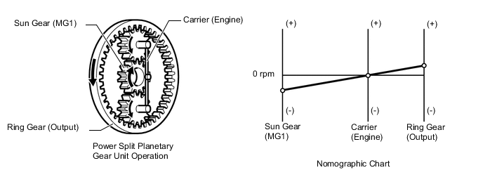
Condition of Power Split Planetary Gear Unit Condition Sun Gear (MG1) Carrier (Engine) Ring Gear (Output) Rotational Direction - 0 + Torque 0 0 +
-
-
Running with MG2 and Engine
-
Only when running with MG2, when the engine starts with MG1, the torque acts on the sun gear (MG1) in the (+) direction, the carrier rotates in the (+) direction in reaction to the torque transmitted by the sun gear. The ring gear rotates in the (+) direction in reaction to the carrier rotation.
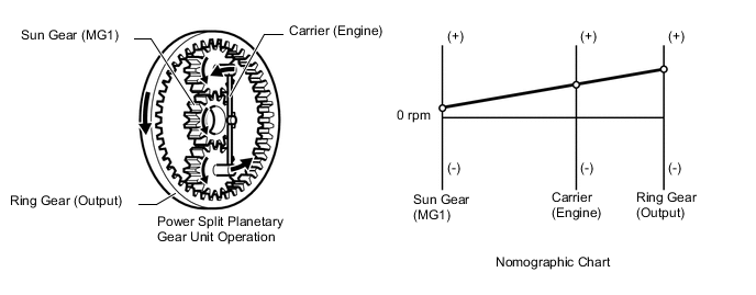
Condition of Power Split Planetary Gear Unit Condition Sun Gear (MG1) Carrier (Engine) Ring Gear (Output) Rotational Direction + + + Torque + - +
-
-
During Low Load and Constant-speed Cruising
-
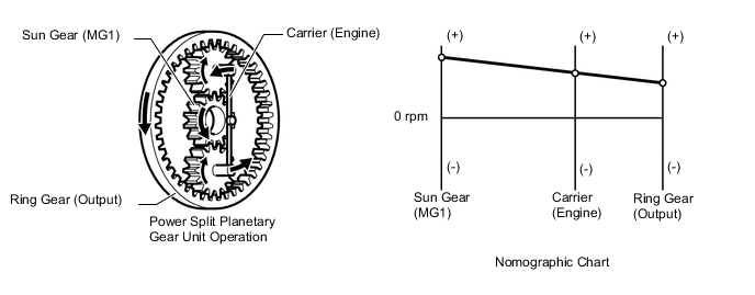
The condition described below is one of the examples of the power split planetary gear unit operation in low load and constant-speed cruising. The sun gear, carrier and ring gear rotate in the (+) direction. Torque acts on the carrier in the (+) direction. As the reaction to that, torque acts on the sun gear and ring gear in the (-) direction. MG1 generates electricity as a result of the torque that acts on the sun gear in the (-) direction.
Condition of Power Split Planetary Gear Unit Condition Sun Gear (MG1) Carrier (Engine) Ring Gear (Output) Rotational Direction + + + Torque - + -
-
-
During Full Throttle Acceleration
-
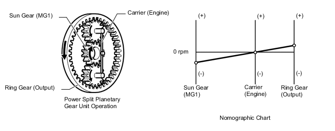
When the large motive force of the engine is required, the engine speed becomes high. As a result, the relationship between the rotational speeds of the gears in the power split planetary gear unit may become as in the nomographic chart below. The directions of the torque that acts on each gear are the same as those in the low load and constant-speed cruising.
Condition of Power Split Planetary Gear Unit Condition Sun Gear (MG1) Carrier (Engine) Ring Gear (Output) Rotational Direction + + + Torque - + +
-
-
During Deceleration
-
During deceleration, the ring gear is rotated by the wheels. At this time, the rotational speed of the carrier becomes 0 rpm because the engine stops. Torque does not act on the sun gear because MG1 does not generate any torque. The sun gear rotates freely in the (-) direction due to the relationship with the rotation of the ring gear.
Condition of Power Split Planetary Gear Unit Condition Sun Gear (MG1) Carrier (Engine) Ring Gear (Output) Rotational Direction - 0 + Torque 0 0 +
-
-
Driving in Reverse
-
During reverse driving, the vehicle is driven mainly by the motive force of MG2. At this time, the rotational directions of the gears in the power split planetary gear unit are reverse of those when starting in a normal way. The rotational speed of the carrier becomes 0 rpm because the engine stops. The sun gear rotates freely in the (+) direction due to the relationship with the rotation of the ring gear.
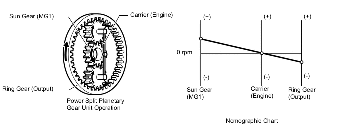
Condition of Power Split Planetary Gear Unit Condition Sun Gear (MG1) Carrier (Engine) Ring Gear (Output) Rotational Direction + 0 - Torque 0 0 -
-
-
-
FAIL-SAFE
-
Even if a malfunction is detected in the electrical part of the hydraulic pressure control system, the hybrid vehicle control ECU affects fail-safe control to prevent the vehicle's driveability from being affected.
-
Fail-safe operation varies depending on the vehicle conditions. For details, refer to the Repair Manual.
-