LANE-KEEPING ASSIST SYSTEM
-
FUNCTION OF MAIN COMPONENTS
Component Outline Object Recognition Camera Captures the road scene ahead of the vehicle and transmits the image data to the object recognition ECU. Object Recognition ECU Processes image data of the road surface captured by the object recognition camera, recognizes lane markers on the driving lane and calculates the lateral deviation from the lane center, heading angle deviation, radius to the lane center and lane width. LKA Main Switch Sends the on/off state to the driving support ECU assembly. Near-infrared Ray Projector Built into the headlight assembly, and emits near-infrared rays to detect obstructions using the object recognition camera. Driving Support ECU Assembly
-
Calculates the amount of steering assist in accordance with signals from switches, ECUs and object recognition camera.
-
Transmits the LKA indicator light illumination request signal, multi-information display indication request signal and multi buzzer sound request signal to the combination meter assembly.
Skid Control ECU Assembly
-
Sends the vehicle speed signal from the speed sensor to the driving support ECU assembly.
-
Sounds the skid control buzzer assembly in accordance with a request signal from the driving support ECU assembly.
Power Steering ECU Assembly
-
Controls the power steering motor in accordance with signals from the driving support ECU assembly.
-
Detects the driver's steering input and transmits it to the driving support ECU assembly.
Combination Meter Assembly LKA Indicator Light Illuminates to warn the driver in accordance with signals from the driving support ECU assembly. Multi-information Display Displays a warning message to inform or warn the driver of the system condition in accordance with signals from the driving support ECU assembly. Master Warning Light Illuminates to warn the driver in accordance with signals from the driving support ECU assembly. Multi Buzzer Sounds to warn the driver in accordance with signals from the driving support ECU assembly. Power Steering Link Assembly Power Steering Motor Applies a steering assist force. Torque Sensor Detects the driver's steering input and transmits it to the power steering ECU assembly. Skid Control Buzzer Assembly Sounds to warn the driver in accordance with signals from the skid control ECU assembly. Yawrate Sensor Detects yaw rate and transmits a signal to the driving support ECU assembly. Speed Sensor Transmits the vehicle speed signal to the skid control ECU assembly. Cruise Control Main Switch Assembly Transmits the cruise control main switch assembly signal to the driving support ECU assembly. Stop Light Switch Assembly Detects the depressing of the brake pedal and transmits a signal to the driving support ECU assembly. Headlight Dimmer Switch Assembly Transmits a turn signal command to the driving support ECU assembly. Windshield Wiper Switch Assembly Transmits wiper switch information to the driving support ECU assembly. -
-
OPERATING CONDITION
-
Lane-keeping Assist System Operating Conditions
-
The lane-keeping assist system can be activated by pressing the LKA main switch. At this time, the LKA indicator light in the combination meter assembly illuminates.
-
The operating conditions of the lane-keeping assist system lane departure warning function and lane-keeping assist function differ in accordance with the on/off status of the dynamic radar cruise control system and the vehicle speed.
LKA Main Switch Dynamic Radar Cruise Control System Vehicle Speed Function On Off Approximately 48 km/h to 200 km/h (30 mph to 125 mph) Lane Departure Warning On Approximately 48 km/h to 72 km/h (30 mph to 45 mph) Lane Departure Warning Approximately 72 km/h to 180 km/h (45 mph to 112 mph) Lane-keeping Assist Approximately 180 km/h to 200 km/h (112 mph to 125 mph) Lane Departure Warning
-
-
Lane-keeping Assist System Cancel Conditions
-
The lane departure warning function and the lane-keeping assist function suspension conditions are as follows. However, if it is confirmed that the conditions which caused operation to be suspended are canceled, the system will be reactivated.
Lane Departure Warning Function The vehicle speed is not between approximately 48 km/h and 200 km/h (30 mph and 125 mph). The turn signal command is detected. The steering force input is above a certain level. No lane markers are detected. The yawrate sensor is malfunctioning. Immediately after the lane departure warning is activated. However, if a few seconds has elapsed and it is confirmed that the vehicle is running inside lane markers, the system will be reactivated. Lane-keeping Assist Function The vehicle speed is not between approximately 72 km/h (45 mph) and 180 km/h (112 mph). The turn signal command is detected. The steering force input is above a certain level. The windshield wiper switch position is high. No lane markers are detected. The yawrate sensor is malfunctioning. More than approximately half of the vehicle is judged to have crossed a lane marker. No steering force is detected for a certain period of time.
-
-
Lane-keeping Assist System Stop Conditions
-
The lane departure warning function and the lane-keeping assist function stop, and restart conditions are as follows:
Lane Departure Warning Function Stop Condition Restart Condition The LKA main switch is turned off The LKA main switch is turned on. The system is temporarily stopped The system will be reactivated if the following conditions are met:
-
The LKA main switch is turned on again.
-
The LKA system condition is normal.
The system is malfunctioning The system will be reactivated if the following conditions are met:
-
The power switch is turned on (IG) again.
-
The LKA main switch is turned on again.
-
The LKA system condition is normal.
The power switch is turned off The LKA main switch is turned on after the power switch is turned on (IG) again. Lane-keeping Assist Warning Function Stop Condition Restart Condition The LKA main switch is turned off The LKA main switch is turned on. The dynamic radar cruise control system is canceled* Dynamic radar cruise control is turned on again. The brake is operated* Dynamic radar cruise control is turned on again. The system is temporarily stopped If the LKA main switch is in on state, the system will be automatically reactivated after the temporary stop is canceled. The system is malfunctioning The system will be reactivated if the following conditions are met:
-
The power switch is turned on (IG) again.
-
The LKA main switch is turned on again.
-
The LKA system condition is normal.
The power switch is turned off The LKA main switch is turned on after the power switch is turned on (IG) again. Tech Tips
The LKA main switch is turned on after the engine switch is turned on (IG) again.
-
-
-
-
SYSTEM CONTROL
-
The lane-keeping assist system has the following functions:
Function Outline Lane Departure Warning When the system determines that the vehicle is about to deviate from its lane, the system urges the driver to correct the lane deviation by displaying a warning message, sounding the multi buzzer and applying a small amount of steering force. Lane-keeping Assist When cruise control is in operation, the system applies a small amount of steering force using EPS to assist driver's steering operation. -
Lane Departure Warning Function
-
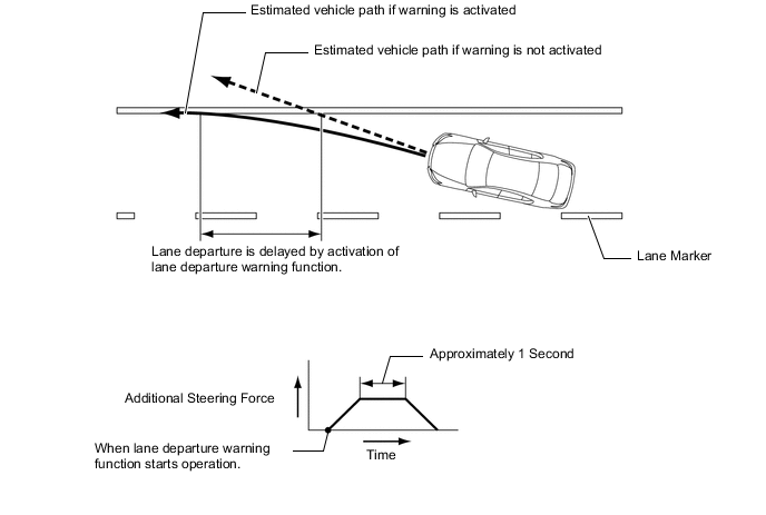
The driving support ECU assembly calculates the estimated position which the front wheel will reach after approximately 1 second based on the information collected by the object recognition camera, vehicle speeds and front wheel positions. When the driving support ECU assembly determines that the front wheel is about to cross the lane marker, the driving support ECU assembly activates the lane departure warning function, displays a warning message on the multi-information display, sounds the skid control buzzer assembly and applies a small amount of steering force by activating the power steering motor for approximately 1 second to urge the driver to correct the steering.
-
The lane departure warning function does not operate if the vehicle approaches the lane marker (but does not cross it), as long as the vehicle remains parallel with the lane marker.
-
-
Lane-keeping Assist Function
-
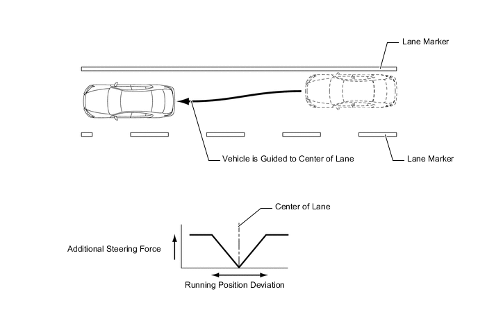
The driving support ECU assembly activates the power steering motor via the power steering ECU assembly based on the road information collected by the object recognition camera and assists in the driver's steering operation to keep the vehicle near the center of the lane.
-
The driving support ECU assembly constantly calculates and controls the steering assist force in accordance with the radius of the curve on the lane, heading angle deviation and lateral deviation from the center of the lane.
-
If the driving support ECU assembly determines that the vehicle is deviating from the lane, the skid control ECU assembly sounds the skid control buzzer assembly. At this time, the driving support ECU assembly displays a warning message on the multi-information display to warn the driver of lane deviation.
-
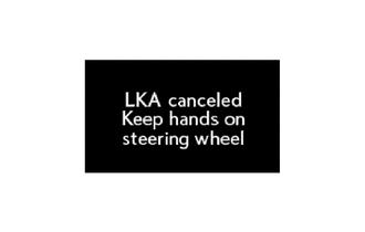
If the driver's steering input is not detected for a certain period, the driving support ECU assembly alerts the driver by sounding the multi buzzer in the combination meter assembly and by displaying a message on the multi-information display.
-
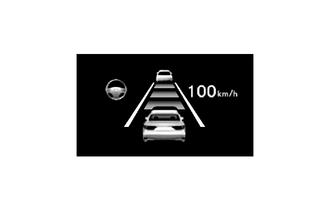
The lane-keeping assist function is activated when the LKA main switch is turned on while the steering wheel icon is indicated on the multi-information display. If the icon is not displayed, the function is not activated when the LKA main switch is turned on.
-
-
-
FUNCTION
-
Combination Meter Assembly
-
For the combination meter assembly, a master warning light, LKA indicator light, multi buzzer and multi-information display are provided to give warnings and messages regarding the lane-keeping assist system in accordance with functions. In addition, the skid control buzzer assembly sounds when the warning is operated.
-
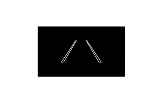
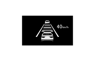
The multi-information display displays the lane departure warning function, lane-keeping assist function and warning message. During the operation of each function, the lane marker icons are displayed in bold.
Lane Departure Warning Function (LKA Main Switch On and Radar Cruise Control System Off) Condition Multi-information Display LKA Indicator Light Multi Buzzer Skid Control Buzzer Assembly
-
Approximately 48 km/h to 200 km/h (30 mph to 125 mph)
-
Lane Markers Detected

Illuminates - -
-
Approximately 48 km/h to 200 km/h (30 mph to 125 mph)
-
One Side of Lane Markers Detected

Warning Operating The lane marker icons blink
Illuminates - Sounds Countinuously
-
Approximately 48 km/h (30 mph) or Higher
-
Lane Markers not Detected
Illuminates - - Below Approximately 48 km/h (30 mph) Lane-keeping Assist Function (LKA Main Switch On and Radar Cruise Control System On) Condition Multi-information Display LKA Indicator Light Multi Buzzer Skid Control Buzzer Assembly
-
Approximately 72 km/h to 180 km/h (45 mph to 112 mph)
-
Lane Markers Detected
Illuminates - -
-
Approximately 72 km/h to 180 km/h (45 mph to 112 mph)
-
Lane Markers Detected
-
Lane Deviation Warning Operating
The steering wheel and lane marker icons blink
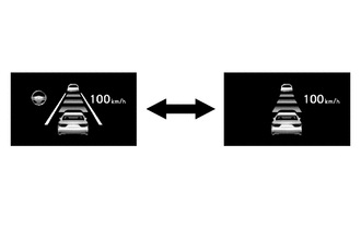
Illuminates - Sounds Countinuously
-
Approximately 72 km/h to 180 km/h (45 mph to 112 mph)
-
Lane Markers Detected
-
No Steering Force Input Detected for Certain Period of Time
Illuminates Sounds Twice -
-
Below Approximately 72 km/h (45 mph) or 180 km/h (112 mph) or Higher
-
Lane Markers Detected
Illuminates - -
-
Below Approximately 72 km/h (45 mph) or 180 km/h (112 mph) or Higher
-
One Side of Lane Marker Detected
Illuminates - - Lane Marker not Detected 
Illuminates - - Warning Message Condition Multi-information Display LKA Indicator Light Multi Buzzer Skid Control Buzzer Assembly
-
Temperature of Object Recognition Camera is Abnormal
-
EPS System is Malfunctioning or Abnormal.

- - Sounds System Malfunction 
- Illuminates Sounds Object Recognition Camera Angle Adjustment 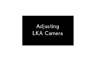
Illuminates Illuminates - -
-
-
-
CONSTRUCTION
-
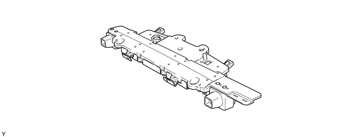
Object Recognition Camera
-
The object recognition camera is mounted at the top center portion of the top part of the windshield glass.
Tech Tips
When one of the following operations is conducted, the object recognition camera angle must be adjusted:
-
The object recognition camera is removed and reinstalled or replaced.
-
Parts relating to the suspension are adjusted or replaced.
For details, refer to the Repair Manual.
-
-
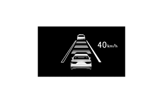
The object recognition camera captures an image of the road up to approximately 30 m (98 ft.) ahead of the vehicle. In addition, the detectable lane width is approximately 3 m to 4 m (9 ft. to 13 ft.).
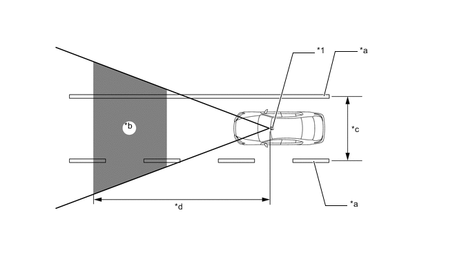
Text in Illustration *1 Object Recognition Camera - - *a Lane Marker *b Image Processing Range *c Approximately 3 m to 4 m (9 ft. to 13 ft.) *d Approximately 30 m (98 ft.) -
By processing the road image data, the object recognition camera detects lane markers and calculates the radius to the center of the lane, heading angle deviation, lateral deviation from the center of the lane and lane width.
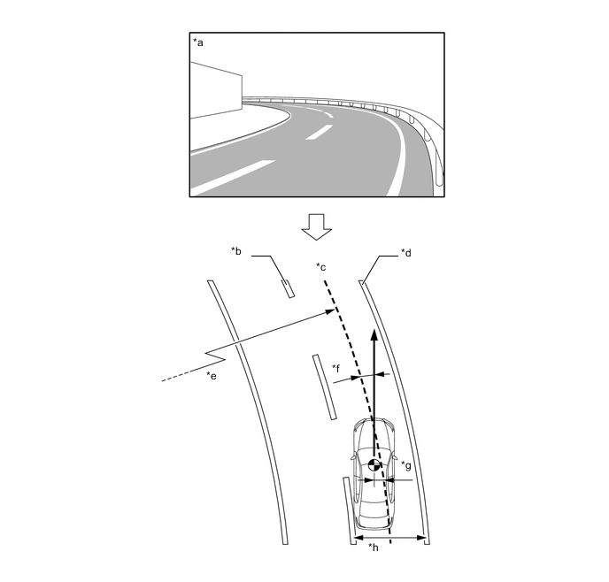
Text in Illustration *a Image Captured by Object Recognition Camera *b Left Lane Marker *c Center of Lane *d Right Lane Marker *e Radius to Center of Lane *f Heading Angle Deviation *g Lateral Deviation *h Lane Width
-
-
-
DIAGNOSIS
-
If a malfunction is detected in the lane-keeping assist system, the driving support ECU assembly stops the system, turns off the LKA indicator light, illuminates the master warning light, sounds the multi buzzer, and outputs a warning message on the multi-information display to inform the driver of the malfunction. At the same time, the malfunction is stored in memory as a Diagnostic Trouble Code (DTC).
-