DYNAMIC RADAR CRUISE CONTROL SYSTEM
-
FUNCTION OF MAIN COMPONENTS
-
The main components in the dynamic radar cruise control system have the following functions:
Component Function Millimeter Wave Radar Sensor Assembly
-
Radiates millimeter radio wave forward, uses the reflected millimeter radio wave for detecting the presence of a vehicle being driven ahead, the vehicle-to-vehicle distance, and the relative speed, and transmits these pieces of information to the driving support ECU assembly.
-
This sensor is also used in the pre-crash safety system.
Cruise Control Main Switch Assembly ON-OFF Button Turns on/off the power to the cruise control system. MODE Switch Switches between the constant speed control mode and vehicle-to-vehicle distance mode. CANCEL Switch A cancel signal can be output to the driving support ECU assembly through the operation of this switch. +RES Switch The acceleration function and resumption of a preset speed can be performed by operating this switch. A signal is output to the driving support ECU assembly when this switch is operated. -SET Switch The deceleration function and vehicle speed setting resume signals are output to the driving support ECU assembly due to operation of this switch. Distance Control Switch While the system is in the vehicle-to-vehicle distance control mode, the driver can operate the distance control switch to select the vehicle-to-vehicle distance in three stages: long, middle and short. Driving Support ECU Assembly
-
Calculates the motive force required to achieve the target vehicle speed/target vehicle-to-vehicle distance based on signals from switches, sensors and ECUs and transmits motive force request signals to the hybrid vehicle control ECU (to accelerate the vehicle in accordance with the motive force request) and the skid control ECU assembly (to decelerate the vehicle in accordance with the motive force request).
-
Determines the presence of a preceding vehicle based on information from the millimeter wave radar sensor assembly.
-
Detects vehicles outside the detection area of the millimeter wave radar sensor assembly based on the information from the object recognition camera (object recognition ECU) which has a wider detection area than the millimeter wave radar sensor assembly, and controls the vehicle speed, such as suppressing vehicle acceleration.
-
Transmits control status display request signals, warning display request signals and diagnosis signals for the dynamic radar cruise control system.
Hybrid Vehicle Control ECU
-
Increases and decreases the motive force in accordance with the motive force request signals transmitted by the driving support ECU assembly.
-
Transmits the information about motive forces that are actually generated and can be generated to the driving support ECU assembly.
ECM Actuates the throttle control motor in accordance with the signals from the hybrid vehicle control ECU. Skid Control ECU Assembly
-
Performs brake control in accordance with motive force request signals from the driving support ECU assembly while the system is operating in vehicle-to-vehicle distance control mode.
-
Transmits signals such as a wheel speed and estimated vehicle acceleration to the driving support ECU assembly.
-
Keeps the vehicle stopped through the brake hold function upon receiving a stop retention signal from the driving support ECU assembly.
Combination Meter Assembly Cruise Control Main Indicator Light
-
Illuminates when the constant speed mode is on.
-
Turns off when the distance control ECU detects a malfunction.
Radar Cruise Control Indicator Light
-
Illuminates when the ON-OFF button on the cruise control main switch assembly has been pressed to turn the system on.
-
Turns off when the driving support ECU assembly detects a malfunction.
Cruise Control SET Indicator Light Illuminates when the constant speed control mode or the vehicle-to-vehicle distance control mode is set. Master Warning Light Illuminates when there is a malfunction in the system. Multi Buzzer Sounds to inform the driver when the driving support ECU assembly detects automatic cancel or warning signals while the vehicle is operating under cruise control. Multi-information Display Receives signals from driving support ECU assembly in order to display the system conditions during the dynamic radar cruise control. Throttle Control Motor
-
Adjusts the throttle valve opening angle in accordance with signals from the ECM. (Throttle Control Motor)
-
Detects the throttle valve opening angle and outputs it to the ECM. (Throttle Position Sensor)
Inverter with Converter Assembly
- MG ECU
Controls the motive force of the Motor Generator No. 2 (MG2) in accordance with signals from the hybrid vehicle control ECU. Brake Actuator Assembly Actuates the brakes in accordance with the signals from the skid control ECU assembly. Front Controller (Multiplex Network Front Light ECU) Transmits the wiper operation status (in HI mode) to the driving support ECU assembly when the wiper switch is set to the AUTO position. Rear J/B ECU (Luggage Room Junction Block Assembly) Illuminates the stop light in accordance with the stop light on request signal from the skid control ECU assembly. Skid Control Buzzer Assembly Sounds on receiving a signal from the skid control ECU assembly and alerts the driver that the distance between vehicles is short. Accelerator Pedal Sensor Assembly Detects the accelerator pedal depression degree and outputs it to the hybrid vehicle control ECU. Shift Lever Position Sensor Converts the shift position into an electrical signal and outputs it to the hybrid vehicle control ECU. Steering Sensor Detects the angle and direction of steering and transmits signals to the driving support ECU assembly. Yawrate Sensor Detects the yaw rate of the vehicle and transmits signals to the driving support ECU assembly. Stop Light Switch Assembly Detects the depression of the brake pedal and transmits a signal to the driving support ECU assembly. Windshield Wiper Switch Assembly Transmits windshield wiper switch assembly information (HI position) to the driving support ECU assembly. Combination Switch Assembly (SNOW Mode Switch) Transmits SNOW mode switch information to the driving support ECU assembly via the driver side switch module (outer mirror switch assembly). Electric Parking Brake Switch Assembly Outputs a parking brake application signal to the electric parking brake ECU assembly. Parking Brake ECU Assembly During stop retention control, when this ECU detects that the vehicle is parked through a driver side courtesy switch signal or driver side seat belt buckle switch signal, or an electric parking brake switch assembly signal is input, the ECU operates the parking brake, then the system control is canceled. Transmission Floor Shift Assembly (Transmission Control Switch) While the vehicle is being driven in S mode, this switch outputs a signal to the hybrid vehicle control ECU when the shift lever is moved toward "+" or "-". Paddle Shift Switch (Transmission Shift Switch Assembly)* While the vehicle is being driven in D mode or S mode, this switch outputs a signal to the hybrid vehicle control ECU when the switch is pulled to "+" or "-".
-
*: Models with paddle shift switch (transmission shift switch assembly)
-
-
-
FUNCTION
-
Control of Dynamic Radar Cruise Control System Varies Depending on Mode
-
A: Constant speed control mode
-
B: Vehicle-to-vehicle distance control mode
-
C: Vehicle-to-vehicle distance control mode (models with full-speed following function)
Function Outline Mode A B C Constant Speed Control Controls the motive force through the driving support ECU assembly via the hybrid vehicle control ECU and the skid control ECU assembly in order to adjust the vehicle speed to the set speed. ○ ○ ○ Deceleration Control Effects engine, MG2 and brake control in order to decelerate the vehicle so that the vehicle-to-vehicle distance between this vehicle and the vehicle ahead equals the set distance. - ○ ○ Follow-up Control After effecting deceleration control, the vehicle follows the vehicle ahead in order to maintain the proper vehicle-to-vehicle distance in accordance with the vehicle speed. - ○ ○ Acceleration Control Accelerates the vehicle in order to attain the set vehicle speed if the vehicle ahead or this vehicle has changed lanes. - ○ ○ Stop Control Detects if the vehicle ahead has stopped, performs motive force control and stops the vehicle while maintaining proper vehicle-to-vehicle distance. - - ○ Stop Retention Control Judges if the vehicle is stopped, performs brake control and keeps the vehicle stopped through the brake hold function. - - ○ Start Control Detects that the vehicle ahead starts moving again, displays the message on the multi-information display to urge the driver to perform the start-off operation (to operate the cruise control main switch assembly or depress the accelerator pedal), and resumes follow-up control after the vehicle is started. - - ○ Set Control While this system fulfils the following conditions and the cruise control main switch assembly is pressed to the -SET side and released, the driving support ECU assembly stores the vehicle speed, illuminates the cruise SET indicator light on the combination meter and maintains the vehicle constantly at that speed.
-
The ON-OFF button on the cruise control main switch assembly is pressed.
○ ○ ○
-
The vehicle is running at a vehicle speed of approx. 45 km/h to 200 km/h (27 mph to 125 mph) or more.
○ - -
-
The vehicle is running between approx. 45 km/h and 170 km/h (27 mph and 105 mph). When there is a preceding vehicle, the set speed is kept at approx. 45 km/h [27 mph] even if the vehicle is being driven below that speed.
- ○ ○ Low Speed Limit Control The low speed limit is approx. 40 km/h (25 mph). If the vehicle speed drops below that speed while running under the cruise control, the cruise control will be canceled automatically. It is not canceled when the vehicle is running in mode B and there is a vehicle ahead. However, the set vehicle speed in the memory is kept. ○ ○ ○ COAST (-) Switch Control While the cruise control main switch assembly is held to the -SET side, the vehicle speed and the set vehicle speed change in accordance with the mode as follows: ○ ○ ○
-
The vehicle decelerates constantly.
-
The set vehicle speed changes to the speed as which the switch is releases.
○ - -
-
The vehicle setting speed decreases in increments 5 km/h or 5 mph. [Example: 57 → 55 → 50 km/h, 57 → 55 → 50 mph]
-
The vehicle remains at the speed that the vehicle is traveling at when the cruise control main switch assembly is released.
- ○ ○ Tap-down Control When the cruise control main switch assembly is pushed momentarily (approx. 0.6 sec.) to the -SET side, the vehicle speed and the vehicle setting speed change in accordance with the mode as follows: ○ ○ ○
-
The vehicle decelerates in increments of approx. 5 km/h (5 mph) for each time the switch is pressed. [Example: 57 → 55 → 50 km/h, 57 → 55 → 50 mph]
○ - -
-
The vehicle decelerates in increments of approx. 1.6 km/h (1 mph) for each time the switch is pressed. However, if the difference between the actual vehicle speed and the vehicle setting speed is greater than 5 km/h or 5 mph, the set vehicle speed changes to the speed at which the vehicle was being driven at the time the switch was operated.
- ○ ○ ACC (+) Switch Control When the cruise control main switch assembly is pushed to the +RES side and held, the vehicle speed and the vehicle setting speed change as follows, in accordance with the mode: ○ ○ ○
-
The vehicle accelerates constantly.
-
The set vehicle speed changes to the speed as which the switch is released.
○ - -
-
The vehicle setting speed increases in increments 5 km/h or 5 mph. [Example: 52 → 55 → 60 km/h, 52 → 55 → 60 mph]
-
The vehicle will accelerate to the speed that is set at the time the switch is released.
However, only the vehicle setting speed will change during follow-up control.
- ○ ○ Tap-up Control When the cruise control main switch assembly is pushed momentarily (approx. 0.6 sec.) to the +RES side, the vehicle speed and the vehicle setting speed change in accordance with the mode as follows: ○ ○ ○
-
The vehicle accelerates in increments of approx. 5 km/h (5 mph) for each time the switch is pressed. [Example: 52 → 55 → 60 km/h, 52 → 55 → 60 mph]
○ - -
-
The vehicle accelerates in increments of approx. 1.6 km/h (1 mph) for each time the switch is pressed. However, if the difference between the actual vehicle speed and the vehicle setting speed is greater than 5 km/h or 5 mph, the vehicle setting speed changes to the speed as which the vehicle was being driven at the time the switch was operated.
- ○ ○ RES Switch Control If the vehicle speed is above the low speed limit, the cruise control resumes operation (subsequently pushes the cruise control main switch assembly to the +RES side) to reach the vehicle speed that was set at the time the driver canceled cruise control. ○ ○ ○ Even if the vehicle speed drops below the low speed limit, resumption can be performed when the vehicle speed increases to above the low speed limit. However, resumption can be performed even if the vehicle speed is below the low speed limit when the vehicle is running in mode B and there is a vehicle ahead.) - - ○ If the vehicle ahead changes driving lanes during follow-up control, the vehicle speed is gradually increased to the set vehicle speed. At this time, the vehicle speed can be increased promptly by pushing the cruise control main switch assembly to the +RES side. - ○ ○ After the vehicle ahead has started running again under stop retention control and then the message that urges the driver to perform the start-off operation has been displayed, when the cruise control main switch assembly is pushed to the +RES side, follow-up control is resumed and the vehicle can be accelerated up to the set speed. - - ○ Manual Cancel Control If any of the following signals are sent to the driving support ECU assembly, the cruise control is canceled accordingly:
-
Stop light switch assembly is turned on other than under stop retention control (brake pedal is depressed).
-
Shift lever is moved from D to N.
-
1st, 2nd or 3rd range is selected in S mode position.
-
1st, 2nd or 3rd range is selected in D mode position.*
-
CANCEL switch on signal (cruise control main switch is assembly moved to CANCEL side)
-
Cruise control main switch assembly (ON-OFF button) off signal
-
Parking brake is applied (only during vehicle-to-vehicle distance control mode).
○ ○ ○ Automatic Cancel Control When an automatic cancel signal is sent to the driving support ECU assembly, the cruise control operation is canceled. At this time, the style of the warning to the driver and the control resumption condition varies in accordance with the cancel signal. ○ ○ ○ Mode Switching Control
-
The following operations switch the modes:
-
ON-OFF button on the cruise control main switch assembly is on. (Starts in the vehicle-to-vehicle distance control mode)
-
Cruise control main switch assembly is held in the MODE side. (Approx. 1 second or more)
-
If the switch is pushed to any other side before switching modes, switch the cruise control system off; then, perform steps (a) and (b) again.
○ ○ ○ Other Control Cancellation Conditions If any of the following conditions occur during cruise control driving, the cruise control is canceled. However, the set speed remains in the memory:
-
VSC operates during cruise control driving.
-
TRC operates for a certain period of time during cruise control driving.
-
TRC is off or VSC is off.
○ ○ ○ Tech Tips
○ : Available
- : Not available
*: Models with paddle shift switch (transmission shift switch assembly)
-
-
-
Constant Speed Control Function in Vehicle-to-vehicle Distance Control Mode
-
The driving support ECU assembly compares the actual vehicle speed (wheel speed signal from the skid control ECU assembly) with the set speed under constant speed control in each control mode. When the actual vehicle speed differs from the set speed, the driving support ECU assembly calculates the motive force required to achieve the set speed and transmits motive force request signals to the hybrid vehicle control ECU, thus controlling the motive force optimally and adjusting the vehicle speed to the set speed.
-
In vehicle-to-vehicle distance control mode, the driving support ECU assembly performs deceleration control, follow-up control, acceleration control, stop control, stop retention control or start control based on the information about the vehicle ahead transmitted from the millimeter wave radar sensor assembly.
-
-
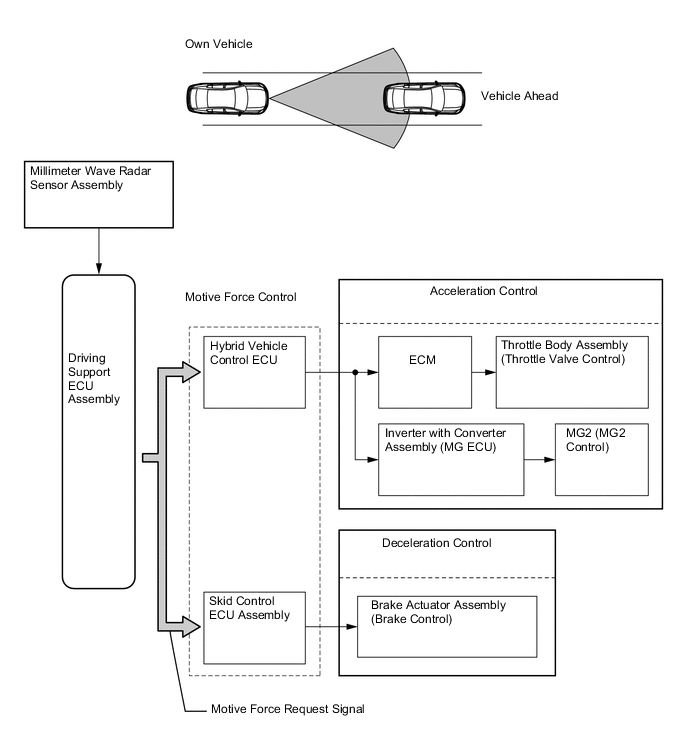
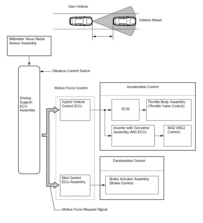
Deceleration Control Function
-
The driving support ECU assembly calculates the target deceleration rate in accordance with signals from the millimeter wave radar sensor assembly, and transmits a motive force request signal to the hybrid vehicle control ECU and the skid control ECU assembly. Upon receiving this signal, these ECUs control the motive force and decelerate the vehicle.
-
This control is not performed in the presence of a parked vehicle or object.
-
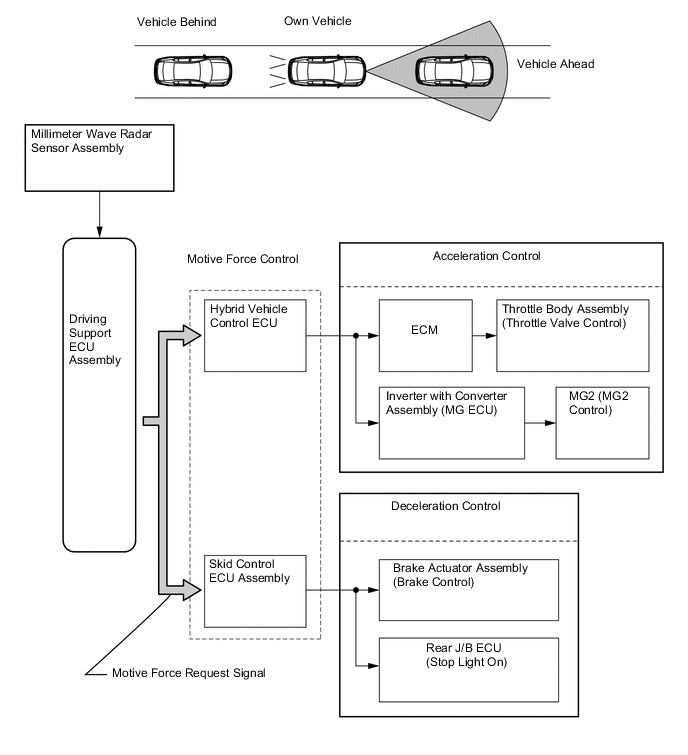
When the driving support ECU assembly determines that further deceleration is necessary, it transmits a motive force request signal to the skid control ECU assembly. Upon receiving this signal, the skid control ECU assembly then activates the brake actuator assembly to apply the brakes.
-
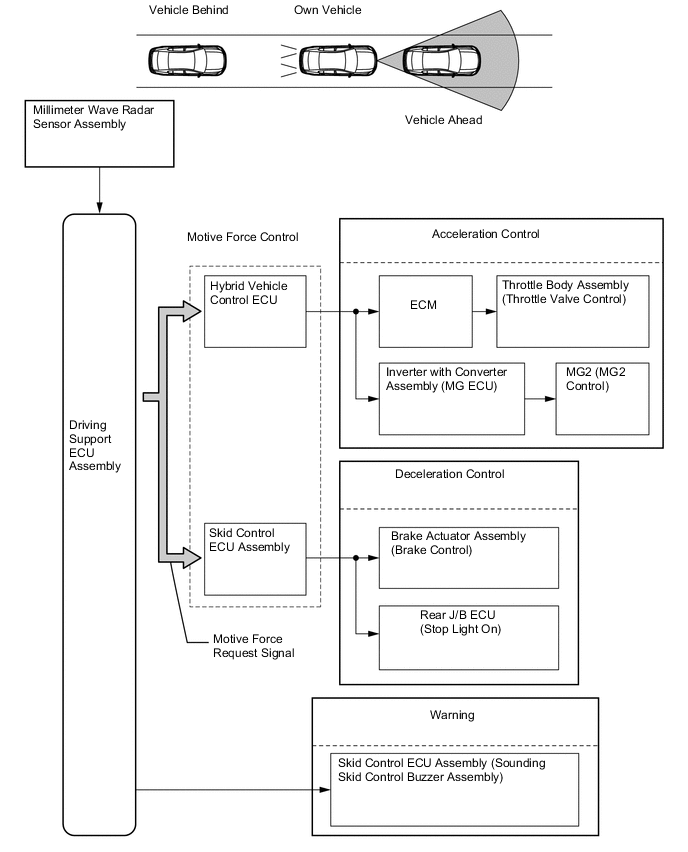
At this time, if the deceleration rate is higher than a predetermined value, the skid control ECU assembly outputs a stop light on request signal to the rear J/B ECU (luggage room junction block assembly), in order to inform anyone who might be following the vehicle.
-
If the vehicle is not decelerating adequately, the skid control ECU assembly sounds the skid control buzzer assembly based on the request signal from the driving support ECU assembly to urge the driver to depress the brake pedal.
-
-
Follow-up Control Function
-
Under follow-up control, the driving support ECU assembly transmits a motive force request signal to the hybrid vehicle control ECU and the skid control ECU assembly, so that the vehicle can follow the vehicle ahead while maintaining a proper vehicle-to-vehicle distance in accordance with the vehicle speed. Upon receiving this signal, these ECUs control the motive force in order to effect follow-up control.
-
Three stages (long, middle and short) of vehicle-to-vehicle distance can be selected by operating the distance control switch.
-
Cruise control is canceled when the vehicle ahead moves off while the driver's own vehicle is being driven at approximately 40 km/h (25 mph) or less. When the driver's own vehicle is being driven at approximately 45 km/h (27 mph) or more, the vehicle speed is controlled in accordance with the set speed.
-
-
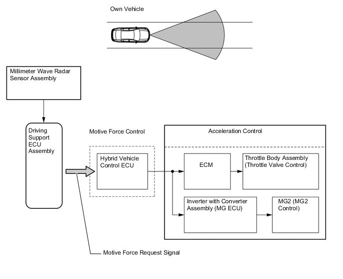
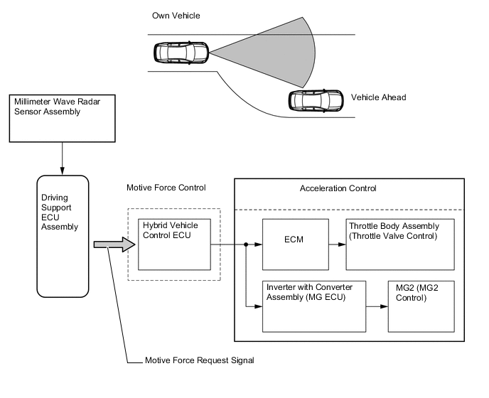
Acceleration Control Function
-
When the vehicle is running at approximately 45 km/h (27 mph) or more, if the driving support ECU assembly detects that either the vehicle ahead or the driver's own vehicle has changed lanes, a motive force signal is transmitted to the hybrid vehicle control ECU in order to attain the set vehicle speed. Upon receiving this signal, the hybrid vehicle control ECU controls the motive force of the engine in order to perform acceleration control.
-
-
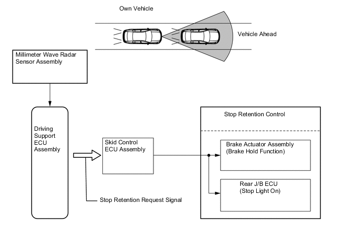
Stop Control (Models with Full-speed Following Function)
-
The driving support ECU assembly detects if the vehicle ahead stops through the signals from the millimeter wave radar sensor assembly and calculates the motive force required to stop the driver's own vehicle while maintaining the appropriate vehicle-to-vehicle distance. The ECU then transmits the motive force request signals to the hybrid vehicle control ECU and the skid control ECU assembly. Upon receiving this signal, these ECUs control the motive force and stop the vehicle.
-
At this time, the skid control ECU assembly outputs a stop light on request signal to the rear J/B ECU (luggage room junction block assembly), in order to inform anyone who might be following the vehicle.
-
The distance between the driver's own vehicle and the preceding vehicle when the vehicles are stopped is set to approximately 3 m to 5 m (10 ft. to 16 ft.) regardless of the vehicle-to-vehicle distance preset by using the distance control switch.

-
-
Stop Retention Control (Models with Full-speed Following Function)
-
After the vehicle has stopped under stop control, the driving support ECU assembly transmits a stop retention request signal to the skid control ECU assembly. Upon receiving this signal, the skid control ECU assembly activates the brake hold function and keeps the vehicle stopped.
-
-
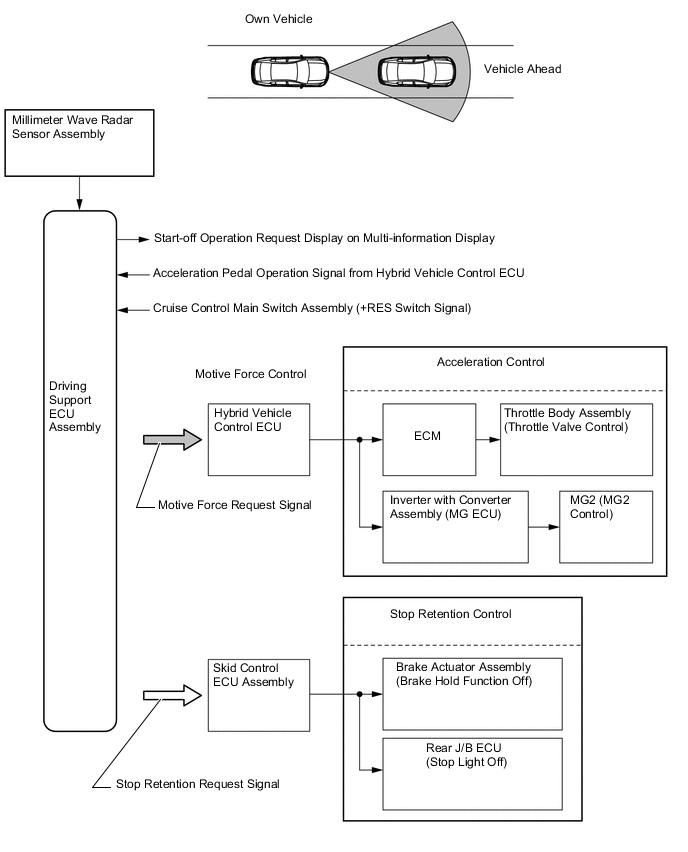
Start Control (Models with Full-speed Following Function)
-
When the driving support ECU assembly detects that the vehicle ahead starts moving again from the millimeter wave radar sensor assembly signal, it displays the messages "PRECEDING VEHICLE MOVEMENT" and "Operate cruise lever or accelerator pedal to resume" on the multi-information display to urge the driver to perform the start-off operation (to push the cruise control main switch assembly to the +RES side or to depress the accelerator pedal).
-
On receiving the start-off operation signal generated by pushing the cruise control main switch assembly to the +RES side or by depressing the accelerator pedal, the driving support ECU assembly transmits a motive force request signal to the hybrid vehicle control ECU. Upon receiving this signal, the hybrid vehicle control ECU controls the motive force of the engine and MG2, starts the vehicle and resumes follow-up control.
-
-
Automatic Cancel Control
-
When any of the conditions listed below occur while the vehicle is in cruise control, the cruise control is canceled. Then, the following warnings appear for the driver.
Constant Speed Control Mode Description of Malfunction Warning Multi-information Display Master Warning Light Buzzer Cruise Control Main Indicator Light If either of the conditions listed below occur, the driving support ECU assembly clears the vehicle setting speed and cancels the cruise control:
-
Malfunction of the wheel speed signal from the skid control ECU assembly
-
An open or short circuit in the stop light switch assembly
-
Malfunction of the throttle control system
The cruise control is prohibited until the conditions are remedied or the cruise control system is turned off and back on again using the ON-OFF button on the cruise control main switch assembly.
Check Cruise Control System Illuminates Sounds Once (Multi Buzzer) - If the condition listed below occurs, the driving support ECU assembly cancels the cruise control while retaining the vehicle setting speed in its memory:
-
The vehicle speed drops below the low speed limit [approx. 40 km/h (25 mph)].
- - - - If the condition listed below occurs, the driving support ECU assembly clears the vehicle setting speed and cancels the cruise control:
-
The vehicle speed drops more than approx. 16 km/h (10 mph) below the vehicle setting speed.
- - - - Vehicle-to-vehicle Distance Control Mode Description of Malfunction Warning Multi-information Display Master Warning Light Buzzer Radar Cruise Control Indicator Light If either of the conditions listed below occur, the driving support ECU assembly clears the vehicle setting speed and cancels the cruise control:
-
Malfunction of the wheel speed signal from the skid control ECU assembly
-
An open or short circuit in the stop light switch assembly
-
Malfunction of the throttle control system
The cruise control is prohibited until the conditions are remedied or the cruise control system is turned off and back on again using the ON-OFF button on the cruise control main switch assembly.
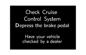
Check Cruise Control System Illuminates Sounds Once (Multi Buzzer) - Cruise Control not available Depress the brake pedal*1 Sounds Continuously (Skid Control Buzzer)*1 If the condition listed below occurs, the driving support ECU assembly cancels the cruise control while retaining the vehicle setting speed in its memory
-
The vehicle speed drops below the low speed limit [approx. 40 km/h (25 mph)].
- - Sounds Twice (Multi Buzzer) - If the condition listed below occurs, the driving support ECU assembly clears the vehicle setting speed and cancels the cruise control:
-
Electronically Controlled Brake (ECB) System parts malfunction
The cruise control is prohibited until the conditions are remedied or the cruise control system is turned off and back on again using the ON-OFF button on the cruise control main switch assembly.
Check Cruise Control System Illuminates Sounds Once (Multi Buzzer) - Cruise Control not available Depress the brake pedal*1 Sounds Continuously (Skid Control Buzzer)*1 If any of the conditions listed below occur, the driving support ECU assembly clears the vehicle setting speed and cancels the cruise control.
-
Malfunction of the millimeter wave radar sensor assembly
-
Displacement of the axis of the millimeter wave radar sensor assembly
-
Malfunction in the dynamic radar cruise control system other than those given above
-
Malfunction of the brake hold function*2
The cruise control is prohibited until the power switch is turned on (IG) again.
Check Cruise Control System Illuminates Sounds Once (Multi Buzzer) - Cruise Control not available Depress the brake pedal*1 Sounds Continuously (Skid Control Buzzer)*1 If the condition listed below occurs, the driving support ECU assembly cancels the cruise control while retaining the set vehicle speed in its memory.
-
The millimeter wave radar sensor assembly is dirty.
The cruise control is prohibited until the conditions are remedied or the cruise control system is turned off and back on again using the ON-OFF button on the cruise control main switch assembly.
Clean Radar Sensor Illuminates Sounds Once (Multi Buzzer) Illuminates Cruise Control not available Depress the brake pedal*1 Sounds Continuously (Skid Control Buzzer)*1 If any of the conditions listed below occur, the driving support ECU assembly cancels the cruise control while retaining the set vehicle speed in its memory.
-
The wipers operate at HI speed (including AUTO mode).
-
SNOW mode is selected by using the SNOW mode switch.
-
The measurement becomes extremely unstable due to poor weather conditions.
The cruise control is prohibited until the conditions are remedied or the cruise control system is turned off and back on again using the ON-OFF button on the cruise control main switch assembly.
Cruise Control not available Illuminates Sounds Once (Multi Buzzer) Illuminates Cruise Control not available Depress the brake pedal*1 Sounds Continuously (Skid Control Buzzer)*1 When there is a vehicle ahead, if the condition listed below occurs, the driving support ECU assembly cancels the cruise control while retaining the set vehicle speed in its memory.
-
The vehicle ahead moves away under follow-up control at approx. 40 km/h (25 mph) or less.*2
Cruise not available Under 40 km/h [25 MPH] No preceding vehicles Illuminates Sounds 4 Times (Multi Buzzer) Illuminates Tech Tips
*1: During stop retention control (models with full-speed following function)
*2: Models with full-speed following function
-
-
-
-
CONSTRUCTION
-
Cruise Control Main Switch Assembly
-
The cruise control main switch assembly consists of an ON-OFF button, +RES, MODE, -SET and CANCEL switches. +RES, MODE, -SET and CANCEL switches are a lever that operates in 4 directions.
-
The cruise control main switch assembly is an automatic reset (normally open) type that turns on only when the switch is being operated and turns off as soon as the driver releases the switch. Furthermore, the functions of the control switch are active only when the cruise control system has been turned on using the ON-OFF button on the cruise control main switch assembly.
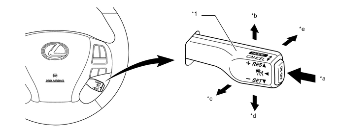
Text in Illustration *1 Cruise Control Main Switch Assembly - - *a ON-OFF Button *b +RES Switch *c CANCEL Switch *d -SET Switch *e MODE Switch - -
-
-
Distance Control Switch
-
While the vehicle is being driven in vehicle-to-vehicle distance control mode, the vehicle-to-vehicle distance setting can be changed each time the distance control switch is pressed, as follows: long or middle or short.
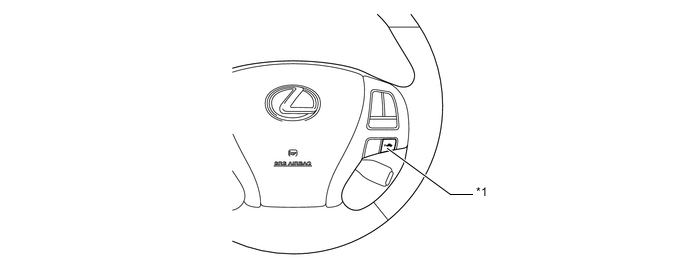
Text in Illustration *1 Distance Control Switch - - -
If the power switch is turned off and back to on (IG), the system will default to "long".
-
The vehicle-to-vehicle distance is set as follows:
Mode Vehicle-to-vehicle Distance* Long Approx. 50 m (160 ft.) Middle Approx. 40 m (130 ft.) Short Approx. 30 m (100 ft.) Tech Tips
*: While driving at a vehicle speed of 80 km/h (50 mph).
-
-
Millimeter Wave Radar Sensor Assembly
-
The millimeter wave radar sensor assembly consists of a millimeter wave radar circuit, signal processing circuit and CPU.
-
The millimeter wave radar circuit consists of a transmission antenna and reception antennas.
-
The millimeter wave radar uses frequencies in the 76.5 GHz band.
-
The reception antennas receive the millimeter wave radar waves that have been reflected.
-
The signal processing circuit detects the distance, relative speed and the direction of the object by generating millimeter wave radar waves and calculating the signals received by the reception antennas. Then, the millimeter wave radar sensor assembly transmits this information to the driving support ECU assembly.
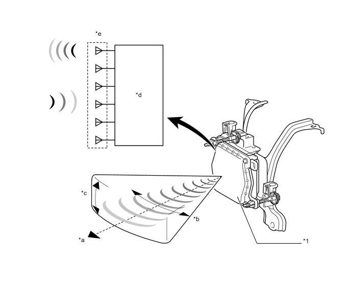
Text in Illustration *1 Millimeter Wave Radar Sensor Assembly - - *a Detection Distance: Approx. 150 m (490 ft.) *b Horizontal Angle: Approx. 20° *c Vertical Angle: Approx. 8° *d Signal Processing Circuit *e Millimeter Wave Radar Circuit - - -
The distance to the object, azimuth (horizontal angle) and relative speed are calculated from the information that is provided by the refection millimeter wave radar wave as described below:
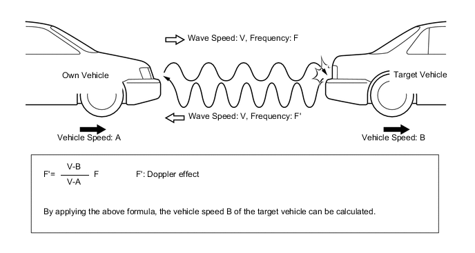
Item Calculation Method Distance Calculated from the length of time has that elapsed between when the waves of the millimeter wave radar were emitted and when they were received. Azimuth Calculated from the angle of the reflected waves that are received. Relative Speed Calculated by utilizing the changes (Doppler effect*) that occur in the frequencies of the reflected millimeter wave radar waves. Tech Tips
*: The Doppler effect causes the observer to perceive the radio waves emitted by a moving object to be at higher frequencies as it approaches, and to be at lower frequencies as it recedes. This phenomenon is created because when an object is located far away, the radio waves are perceived at higher frequencies than they are at the radio source.
-
-
-
OPERATION
-
Combination Meter Assembly
-
The combination meter assembly provides a master warning light, radar cruise control indicator light, cruise control SET indicator light, cruise control main indicator light, multi buzzer and multi-information display to warn and indicate information when the dynamic radar cruise control system is operating.
-
The multi-information display displays the system control status and warning messages.
-
Examples of the illumination or display of each indicator light, warning light or multi-information display are shown below:
Constant Speed Control Mode Condition Multi-information Display Cruise Control Main Indicator Light Cruise Control SET Indicator Light Master Warning Light Multi Buzzer Being Controlled 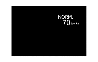
Illuminates Illuminates - - Vehicle-to-vehicle Distance Control Mode Condition Multi-information Display*1 Radar Cruise Control Indicator Light Cruise Control SET Indicator Light Master Warning Light Multi Buzzer Precaution Display (Displayed for 6 sec. after ON-OFF button has been turned on.) 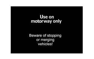
Illuminates - - - Set Standby 
Illuminates - - - Under Constant Speed Control (No Vehicle Ahead) 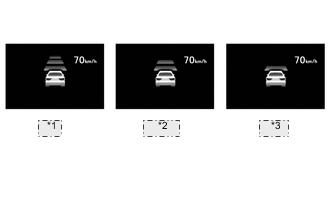
*1 Long *2 Middle *3 Short Illuminates Illuminates - - Under Follow-up Control (Vehicle Ahead) 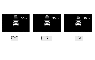
*1 Long *2 Middle *3 Short Illuminates Illuminates - - Under Follow-up Control*2 (The vehicle ahead moves away when the vehicle is being driven at approx. 40 km/h [25 mph] or less.) 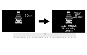
*1 The vehicle-to-vehicle distance mark and vehicle ahead mark blink at intervals of 250 msec, then the cancel display appears. Illuminates Illuminates - - Deceleration Control (Vehicle Ahead) 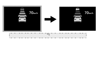
*1 The display frame, vehicle-to-vehicle distance mark and vehicle ahead mark blink at intervals of 250 msec and the skid control buzzer sounds. Illuminates Illuminates - Skid Control Buzzer Sounds Continuously Brake Operation (Vehicle Ahead) 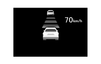
Illuminates Illuminates - - Stop Retention Control*2 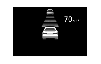
Illuminates Illuminates - - Start Control*2 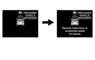
Illuminates Illuminates - - Millimeter wave radar sensor assembly is dirty. 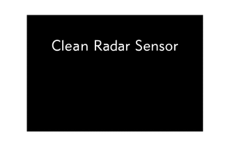
- - Illuminates Sounds Once Poor Weather Conditions 
- - Illuminates Sounds Once System Check 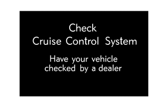
- - Illuminates Sounds Once System Check during Stop Retention Control*2 The skid control buzzer sounds until the brake pedal is depressed.
- - Illuminates Skid Control Buzzer Sounds Continuously When any problem occurs during stop retention control, or any of the following conditions is met:
-
Vehicle is stopped on a steep slope.
-
Millimeter wave radar sensor assembly is dirty.
-
The wipers operate at high speed.
-
ECT-SNOW mode
-
The millimeter wave radar sensor assembly temperature is high.
-
Displacement of axis of the millimeter wave radar sensor assembly.
The skid control buzzer sounds until the brake pedal is depressed.

Illuminates - Illuminates Skid Control Buzzer Sounds Continuously Tech Tips
*1: When the lane-keeping assist system is operating, its indicator is also displayed. For details, see the Lane-keeping Assist System.
*2: Models with full-speed following function
-
-
-