INTAKE SYSTEM
-
CONSTRUCTION
-
Air Cleaner
-
The air cleaner has been split into 2 parts, left and right, and placed directly above the engine. This ensures the proper filtering area and reduces pressure loss.
-
The air cleaner element uses a filter paper that ensures a high level of filtering performance while reducing pressure loss.
-
A dual-chamber resonator is used on the air cleaner hose end where intake air is drawn from both sides. This resonator reduces both high and low frequency noise, thus reducing sound absorbing noise.
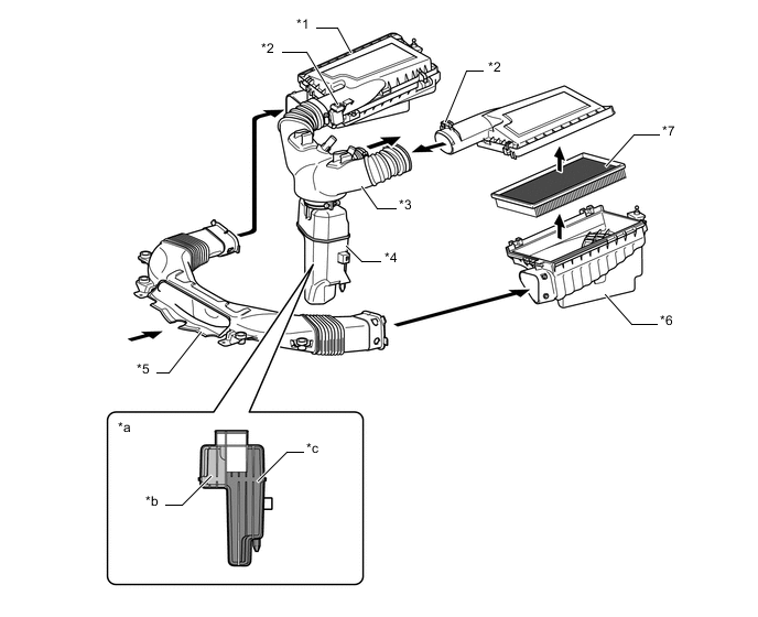
Text in Illustration *1 Air Cleaner Cap *2 Intake Air Flow Meter Sub-assembly *3 Air Cleaner Hose *4 Resonator *5 Air Cleaner Inlet *6 Air Cleaner Case *7 Air Cleaner Element - - *a Resonator Cross Section *b For High Frequency Noise *c For Low Frequency Noise - -
-
-
Throttle Body
-
A linkless-type throttle body in which the throttle position sensor and the throttle control motor are integrated is used to achieve excellent throttle valve control.
-
In the throttle control motor, a DC motor with excellent response and minimal power consumption is used. The ECM performs the duty ratio control of the direction and the amperage of the current that flows to the throttle control motor in order to regulate the throttle valve angle.
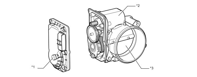
Text in Illustration *1 Throttle Position Sensor Portion *2 DC Motor *3 Throttle Valve - -
-
-
Intake Manifold
-
An intake manifold with a built-in plastic surge tank is used for weight reduction.
-
The port diameter and length have been optimized to achieve high torque and fuel economy in all driving ranges.
-
The intake manifold contains valves for the Acoustic Control Induction System (ACIS), and the actuator is laser-welded to the intake manifold. For details of the ACIS, see the 2UR-FSE Engine Control.
-
The intake air control valve is installed in the intake manifold. The valve opens and closes to provide 2 effective lengths of the intake manifold.
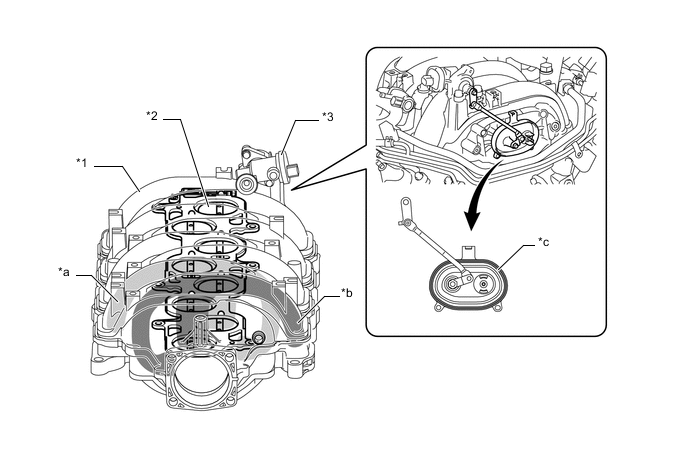
Text in Illustration *1 Intake Manifold *2 Intake Air Control Valve *3 Intake Air Control Valve Actuator - - *a Intake Air Passage to Right Bank *b Intake Air Passage to Left Bank *c Laser-welding - - Tech Tips
Laser-welding: In laser-welding, a laser-absorbing material (for the intake air chamber) is joined to a laser-transmitting material (for the intake air control valve actuator). Laser beams are then irradiated from the laser-transmitting side. The beams penetrate the laser-transmitting material to heat and melt the surface of the laser-absorbing material. Then, the heat of the laser-absorbing material melts the laser-transmitting material and causes both materials to become welded.
-
-