ENGINE UNIT
-
CONSTRUCTION
-
Cylinder Head Cover Sub-assembly
-
Lightweight magnesium alloy diecast cylinder head covers are used.
-
An oil delivery pipe is installed inside the cylinder head cover. This ensures lubrication of the sliding parts of the roller rocker arms, improving reliability.
-
A compact oil separator is used to achieve a compact cylinder head cover.
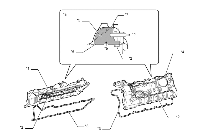
Text in Illustration *1 Cylinder Head Cover Sub-assembly RH *2 Oil Delivery Pipe *3 Cylinder Head Cover Gasket *4 Cylinder Head Cover Sub-assembly LH *5 Oil Separator *6 Baffle Plate *7 Cylinder Head Cover - - *a Oil Separator Cross Section *b Blowby Gas *c To Air Cleaner Hose - -
-
-
Cylinder Head Gasket
-
Cylinder head gaskets with a three-layer metal construction are used. A shim is used around each cylinder bore of the gasket to help enhance sealing performance and durability.
-
The surface is coated with highly heat-resistant fluoro rubber to support high power output.
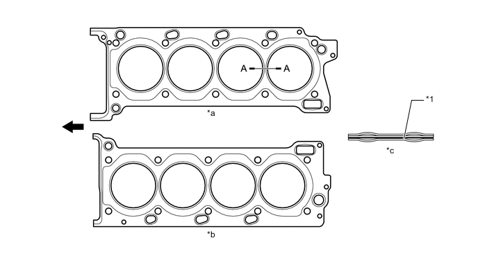
Text in Illustration *1 Shim - - *a For Right Bank *b For Left Bank *c A - A Cross Section - - 
Engine Front - -
-
-
Cylinder Head Sub-assembly
-
The cylinder head structure has been simplified by separating the cam journal portion (camshaft housing) from the cylinder head.
-
The cylinder head, which is made of aluminum, contains a pentroof-type combustion chamber. The spark plug is located in the center of the combustion chamber in order to improve the engine's anti-knocking performance.
-
A taper squish combustion chamber is used to improve anti-knocking performance and intake efficiency. In addition, engine performance and fuel economy have been improved.
-
The port configuration is an efficient cross-flow type in which the intake ports face the inside of the V bank and the exhaust ports face the outside.
-
A siamese type intake port is used. The port diameter gradually decreases toward the combustion chamber to optimize the airflow speed and intake pulsation.
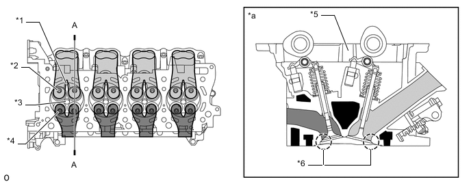
Text in Illustration *1 Injector Hole (for Direct Injection) *2 Intake Valve *3 Spark Plug Hole *4 Exhaust Valve *5 Camshaft Housing *6 Taper Squish *a A - A Cross Section - - 
Intake Side 
Exhaust Side Tech Tips
The difference between a siamese type intake port and an independent type one is shown in the illustration.
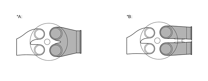
Text in Illustration *A Siamese Type *B Independent Type
-
-
Cylinder Block Sub-assembly
-
Lightweight aluminum alloy is used.
-
The cylinder block has a bank angle of 90°, a bank offset of 21 mm (0.827 in.) and a bore pitch of 105.5 mm (4.15 in.), resulting in a compact block (length and width) for its displacement.
-
Installation bosses of the 4 knock control sensors are located on the inner side of left and right banks. A rib is also used between the left and right banks to enhance the accuracy of the knock control sensors.
-
An engine coolant distribution pathway is provided between the left and right banks. The engine coolant sent by the water pump passes through the engine coolant distribution pathway and flows to the cylinder heads and water jackets of both banks. The engine coolant distribution pathway also cools the engine oil in the main oil hole located directly below the pathway.
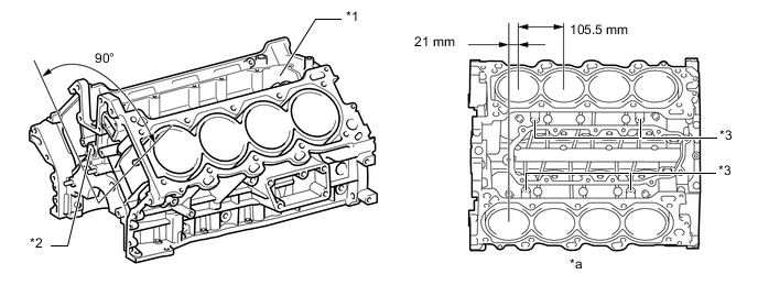
Text in Illustration *1 Engine Coolant Distribution Pathway *2 Main Oil Hole *3 Knock Control Sensor Boss - - *a View from Top Side - - -
Air passage holes are provided in the crankshaft bearing area of the cylinder block. As a result, the air at the bottom of the cylinder flows smoother and pumping loss (back pressure at the bottom of the piston generated by the reciprocal movement of the piston) is reduced to improve the engine's output.
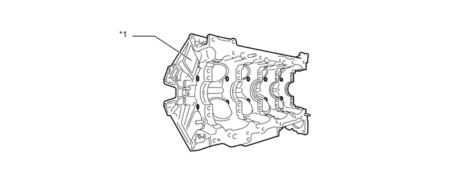
Text in Illustration *1 Cylinder Block - - Air Passage Hole - - -
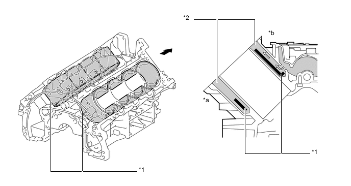
A water passage is provided between the cylinder bores. By allowing the engine coolant to flow between the cylinder bores, this construction enables the temperature of the cylinder walls to be kept uniform.
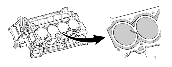
Text in Illustration *1 Water Passage - - -
The spiny-type liners are used.
-
The spiny-type liners are manufactured so that their casting exteriors form large irregular surfaces in order to enhance the adhesion between the liners and the aluminum cylinder block. The enhanced adhesion helps heat dissipation, resulting in a lower overall temperature and heat deformation of the cylinder bores.
-
The shape of the cross-hatching of the liner surface has been optimized to improve oil retention performance, resulting in reduced friction.
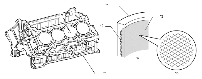
Text in Illustration *1 Cylinder Block *2 Irregularly Shaped Outer Casting Surface of Liner *3 Liner - - *a A - A Cross Section *b Enlarged View of Cross-hatching -
Plastic cylinder block water jacket spacers are inserted in the water jacket. They control the flow of the engine coolant in order to attain a uniform temperature around the combustion chambers.
-
The temperature of the intake side of a cylinder bore tends to be lower. For this reason, a wide cylinder block water jacket spacer covers the cylinder bores in order to suppress the flow of the engine coolant and to prevent excessive cooling. On the other hand, the temperature of the exhaust side of a cylinder bore tends to be higher. A cylinder block water jacket spacer covers the lower area of the cylinder bores in order to direct the engine coolant to the upper area of the cylinder bores where the temperature is higher. This makes the temperature around the cylinder bores more uniform. As a result, the viscosity of the engine oil (which lubricates the area between the wall surface of the cylinder bore and the piston) decreases, thus reducing friction between the cylinder bore and the piston.
Text in Illustration *1 Cylinder Block Water Jacket Spacer *2 Water Jacket *a Exhaust Side *b Intake Side Front Side 
Engine Coolant Flow
-
-
Piston
-
The pistons are made of aluminum alloy.
-
A compact combustion chamber is provided on top of the piston to achieve stable combustion. Together with the pentroof type combustion chamber of the cylinder head, this achieves a high compression ratio, resulting in both high performance and excellent fuel economy.
-
In order to reduce weight, cast holes have been provided on the bottom of the piston head near the pin bosses as shown in the illustration below.
-
The piston skirt is coated with resin to reduce friction losses.
-
The groove of the top ring is coated with alumite (anodic oxide coating) to ensure abrasion resistance.
-
By increasing the machining precision of the cylinder bore diameter in the block, only one size piston is required.
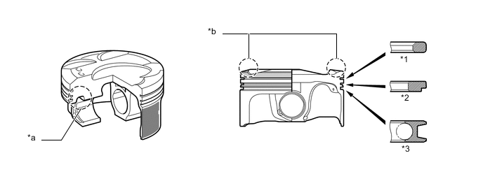
Text in Illustration *1 No. 1 Compression Ring *2 No. 2 Compression Ring *3 Oil Ring - - *a Weight Reduction *b Taper Squish Shape Resin Coating Alumite Coating
-
-
Connecting Rod Sub-assembly and Connecting Rod Bearing
-
Connecting rods that have been forged for high strength are used for weight reduction.
-
Knock pins are used at the mating surfaces of the bearing caps of the connecting rod to minimize the shifting of the bearing caps during assembly.
-
An oil jet is used at the big end of the connecting rod to improve the lubrication of the cylinder bore during idling, thus reducing vibration and noise.
-
Plastic region tightening bolts are used.
-
Resin coated aluminum bearings are used for the connecting rod bearings. The connecting rod bearings are reduced in width to reduce friction.
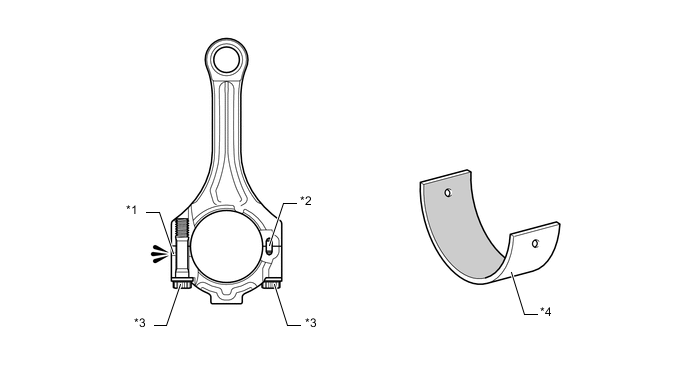
Text in Illustration *1 Oil Jet *2 Knock Pin *3 Plastic Region Tightening Bolt *4 Connecting Rod Bearing Resin Coating - -
-
-
Crankshaft
-
A crankshaft made of forged steel, which excels in rigidity and wear resistance, is used.
-
The crankshaft has 5 main bearing journals and 6 balance weights.
-
The shape of the balance weight and the location of the hollow section have been optimized to reduce the weight of the crankshaft and improve the rotation balance. As a result, vibration and noise are reduced.
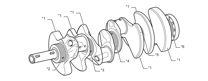
Text in Illustration *1 Balance Weight *2 No. 1 Journal *3 No. 2 Journal *4 No. 3 Journal *5 No. 4 Journal *6 No. 5 Journal
-
-
Crankshaft Bearing and Crankshaft Bearing Cap
-
The crankshaft main bearings are made of aluminum alloy.
-
The crankshaft bearings are reduced in width to reduce friction. The bearing lining surface is coated with resin to improve wear and seizure prevention.
-
The upper main bearing has an oil groove around its inside circumference.
-
The crankshaft bearing caps use 4 plastic-region tightening bolts of different sizes for the inner and outer sides to secure the journals. This makes the crankshaft bearing caps more compact and lightweight. In addition, each cap is tightened laterally to improve its reliability.
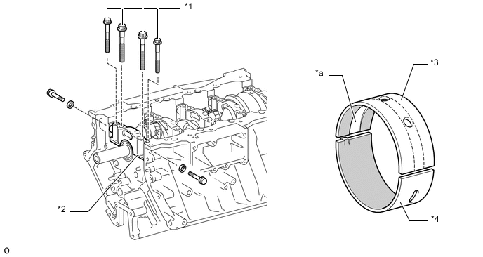
Text in Illustration *1 Plastic Region Tightening Bolt *2 Crankshaft Bearing Cap *3 Upper Main Bearing *4 Lower Main Bearing *a Oil-groove - - Resin Coating - -
-
-
Crankshaft Pulley
-
The crankshaft pulley uses a torsional damper rubber to dampen torsional vibration and a bending damper rubber to dampen bending vibration. This reduces vibration and noise during crankshaft rotation.

Text in Illustration Torsional Damper Rubber Bending Damper Rubber
-
-
Oil Pan
-
The No. 1 oil pan is made of aluminum alloy.
-
To improve quietness, No. 2 oil pan uses vibration damping steel sheets with a resin layer sandwiched in between.
-
The No. 1 oil pan is secured to the cylinder block and the transmission housing to increase rigidity.
-
The shape of the oil pan baffle plate has been optimized to ensure the proper space between the crankshaft and the engine oil surface. This prevents the crankshaft from beating the engine oil surface, which prevents the engine oil from foaming. As a result, friction has been reduced and lubrication performance has been improved.
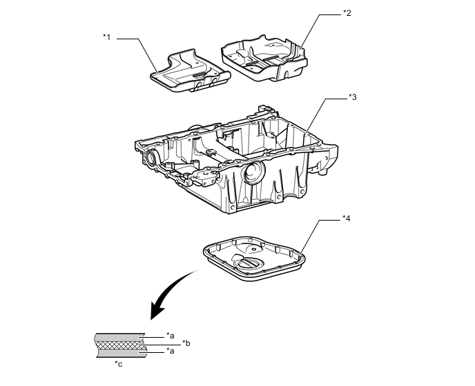
Text in Illustration *1 No. 1 Oil Pan Baffle Plate *2 No. 2 Oil Pan Baffle Plate *3 No. 1 Oil Pan *4 No. 2 Oil Pan *a Steel *b Resin *c No. 2 Oil Pan Cross Section - -
-
-
Separator Case
-
A plastic separator case is provided between the cylinder block and the intake manifold in order to separate the engine oil that is included in the blowby gas.
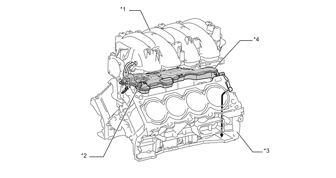
Text in Illustration *1 Intake Manifold *2 PCV Valve (Ventilation Valve Sub-assembly) *3 Cylinder Block *4 Separator Case Engine Oil Blowby Gas 
Blowby Gas Containing Engine Oil - - -
The oil separator in the cylinder head cover has been made compact through the use of a separator case. This contributes to making the entire engine compact.
-
The ventilation inside the engine has been improved and blowby gas is efficiently collected by drawing fresh air from the left and right cylinder head covers.
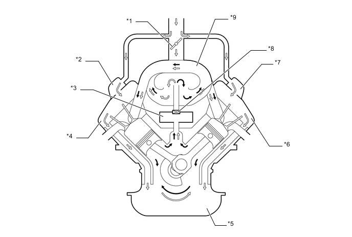
Text in Illustration *1 Throttle Valve *2 Oil Separator Portion RH *3 Separator Case *4 Cylinder Head Cover RH *5 Oil Pan *6 Cylinder Head Cover LH *7 Oil Separator Portion LH *8 PCV Valve *9 Intake Manifold - - Blowby Gas Fresh Air -
An inertial impaction is used in the construction for separating the engine oil in the separator case. The blowby gas that contains engine oil hits the plate, causing the engine oil to adhere and accumulate on the plate. Then, the oil drips down by way of gravity. Thus, this system efficiently separates the engine oil from the blowby gas. This improves the capture ratio of the engine oil and reduces the amount of engine oil consumption.
Text in Illustration *1 Separator Case *2 Plate *3 PCV Valve - - *a From Cylinder Block *b To Intake Manifold *c To Oil Pan - - Blowby Gas Containing Engine Oil Blowby Gas 
Engine Oil - -
-
-
Engine Mount
-
2 engine mounts are provided on each side of the engine and 2 engine mounts are also provided at the back of the transmission.
-
Aluminum engine mount brackets are used for reducing weight, vibration, and noise.
-
A liquid enclosure type front engine mounting is used, which has a mechanism to switch spring characteristics when driving and when idling. As a result, vibrations and noise have been suppressed, thus achieving a comfortable ride.
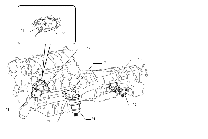
Text in Illustration *1 Dynamic Damper *2 Bracket *3 Front Mount Insulator RH *4 Front Mount Insulator LH *5 Rear Mount Insulator LH *6 Rear Mount Insulator RH *7 Engine Mount Brackets - -
-
-
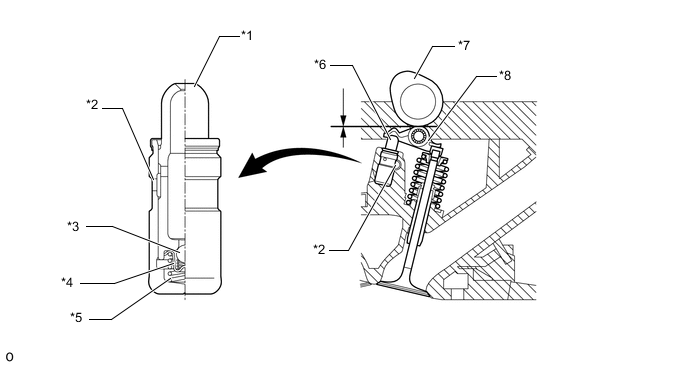
Valve Mechanism
-
Each cylinder of this engine has 2 intake valves and 2 exhaust valves. Intake and exhaust efficiency is increased due to the larger total port areas.
-
This engine uses valve rocker arm sub-assemblies with built-in needle bearings. This reduces the friction that occurs between the cams and the rocker arms that push the valves down, thus improving fuel economy.
-
Valve lash adjuster assemblies, which maintain a constant zero valve clearance through the use of oil pressure and spring force, are used.
-
To ensure highly accurate valve timing, separate primary timing chains are driven by the crankshaft in order to rotate the intake camshafts of the left and right banks. The exhaust camshafts are driven by the intake camshaft of the respective bank via a secondary timing chain.
-
A valve spring, whose upper portion is shaped like a beehive, is used to reduce inertial mass. As a result, the load on the valve spring and friction are reduced.
-
Net-shape sintered composite camshafts are used.
-
This engine has a Dual Variable Valve Timing-intelligent (Dual VVT-i) system which controls the intake and exhaust camshafts to provide optimal valve timing in accordance with driving conditions. As a result, lower fuel consumption, higher engine performance and fewer exhaust emissions have been achieved.
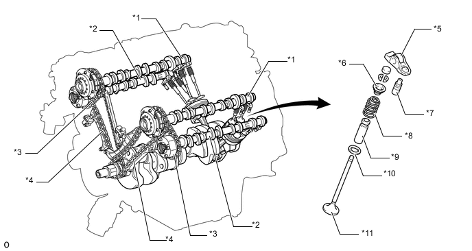
Text in Illustration *1 Intake Camshaft *2 Exhaust Camshaft *3 Timing Chain (Secondary) *4 Timing Chain (Primary) *5 Valve Rocker Arm Sub-assembly *6 Valve Spring Retainer *7 Valve Lash Adjuster Assembly *8 Valve Spring *9 Valve Guide Bush *10 Valve Spring Seat *11 Valve - - 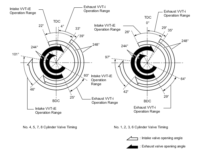
-
-
Camshaft
-
A composite camshaft integrating net-shape sintered cam pieces and a hollow shaft is used for weight reduction.
-
The cam profile has been optimized by the net-shape sintering of the cam pieces, thus improving power output and fuel economy.
-
The materials of the cam pieces have been optimized in accordance with their applications, which are to drive the valves and to drive the pump. This results in improved durability of the camshaft.
-
Optimal valve timing is provided for cylinder numbers 1, 2, 3 and 6, and cylinder numbers 4, 5, 7 and 8. This results in reduced vibration during idling and improved fuel economy.
-
An oil passage is provided in the intake and exhaust camshafts. The intake side is for lubricating the camshaft control actuator (camshaft timing gear assembly) and the exhaust side is for controlling the VVT-i controller (camshaft timing exhaust gear assembly).
-
Together with the use of the valve rocker arm sub-assembly, the cam profile has been modified. This results in increased valve lift when the valve begins to open and finishes closing, helping to achieve enhanced output performance.
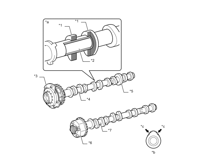
Text in Illustration *1 Cam *2 Hollow Shaft *3 Camshaft Control Actuator (Camshaft Timing Gear Assembly) *4 Intake Camshaft *5 Pump Cam *6 VVT-i Controller (Camshaft Timing Exhaust Gear Assembly) *7 Exhaust Camshaft - - *a Composite Camshaft Cross Section *b Cam Profile *c Amount of valve lift is increased - - Tech Tips
Net-shape Sintering: Net-shape sintering is a shaping method that can create precision formed products by stamping them with dies, without requiring grind finishing.
-
-
VVT-i Controller (Camshaft Timing Exhaust Gear Assembly)
-
The VVT-i controller (camshaft timing exhaust gear assembly) consists of a sprocket driven by the timing chain, a housing coupled with the sprocket and a vane coupled with the exhaust camshaft.
-
The engine oil pressure sent from the advance or retard side path at the exhaust camshaft causes rotation in the VVT-i controller vane circumferential direction to vary the exhaust valve timing continuously.
-
As the engine stops, the advance assist spring moves the VVT-i controller (camshaft timing exhaust gear assembly) to the most advanced position. Then, a lock pin locks the vane to the sprocket in order to ensure engine startability. After the engine is started, engine oil pressure acts on the hole in which the lock pin is engaged to release the lock.
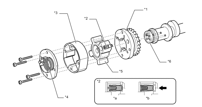
Text in Illustration *1 Sprocket *2 Lock Pin *3 Housing *4 Advance Assist Spring *5 Vane *6 Exhaust Camshaft *a At a Stop *b In Operation Oil Pressure - -
-
-
Timing Chains and Chain Tensioners
-
Both the primary and secondary timing chains use roller chains with a pitch of 9.525 mm (0.375 in.).
-
A timing chain tensioner is provided for each primary chain and secondary chain on each bank.
-
Both the primary and secondary chain tensioners use a spring and oil pressure to maintain proper chain tension at all times. The tensioners suppress noise generated by the timing chains.
-
The chain tensioner for the primary chain is a ratchet type with a non-return mechanism. Furthermore, the gasket is provided with an oil pocket. This creates oil pressure when the engine is started, and simultaneously applies oil pressure to the chain tensioner. This prevents the timing chain from flapping and reduces noise.
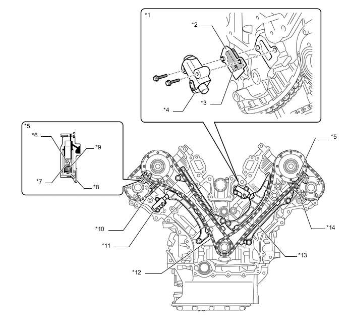
Text in Illustration *1 Chain Tensioner (Primary) LH *2 Gasket *3 Oil Pocket *4 Chain Tensioner (Primary) *5 Chain Tensioner (Secondary) *6 Ball *7 Ball Spring *8 Plunger *9 Main Spring *10 Secondary Chain RH *11 Chain Tensioner (Primary) RH *12 Primary Chain RH *13 Primary Chain LH *14 Secondary Chain LH
-
-
Timing Chain Cover Sub-assembly
-
The timing chain cover has an integrated construction consisting of a cooling system (water pump and water passage) and a lubrication system (oil pump and oil passage). Thus, the number of parts has been reduced to reduce weight.
-
An oil jet is provided in the oil pump housing to lubricate the timing chain.
-
A curved surface has been added to the timing chain cover surface to improve the surface rigidity. This reduces noise emitted from the timing chains.
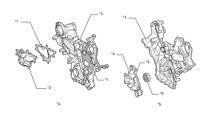
Text in Illustration *1 Water Pump Gasket *2 Water Pump *3 Timing Chain Cover *4 Oil Pump Housing *5 Oil Jet *6 Oil Pump Rotor *a View from Front Side *b View from Back Side *c Curved Surface - -
-
-
Valve Lash Adjuster Assembly
-
The valve lash adjuster assembly, which is located at the fulcrum (pivot point) of the valve rocker arm sub-assembly, consists primarily of a plunger, a plunger spring, a check ball and a check ball spring.
-
Both the engine oil that is supplied by the cylinder head and the built-in spring actuate the valve lash adjuster assembly. The oil pressure and the spring force that act on the plunger push the valve rocker arm sub-assembly against the cam, in order to adjust the clearance between the valve stem and the rocker arm. This prevents the generation of noise during the opening and closing of the valve. As a result, engine noise is reduced.
Text in Illustration *1 Plunger *2 Oil Passage *3 Check Ball *4 Check Ball Spring *5 Plunger Spring *6 Valve Lash Adjuster Assembly *7 Cam *8 Valve Rocker Arm Sub-assembly
-
-
V-ribbed Belt
-
The water pump is driven by a serpentine belt consisting of a single V-ribbed belt.
-
The automatic tensioner eliminates the need for tension adjustment.
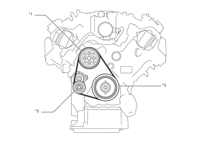
Text in Illustration *1 Water Pump Pulley *2 Idler Pulley for Automatic Tensioner *3 Crankshaft Pulley - -
-
-
V-ribbed Belt Tensioner Assembly
-
The tension of the V-ribbed belt is properly maintained by the tension spring that is enclosed in the V-ribbed belt tensioner assembly.
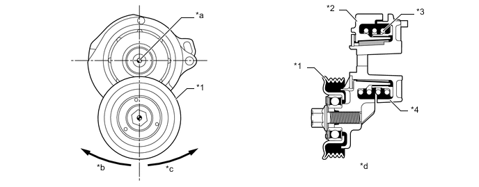
Text in Illustration *1 Idler Pulley *2 Arm *3 Spring *4 Bracket *a Fulcrum *b Belt Tension Direction *c Belt Pulling Direction *d Cross Section
-
-
-
OPERATION
-
Engine Mount
-
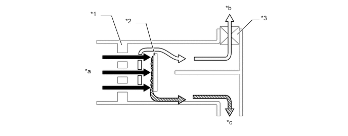
A movable membrane is provided in the flow passage. The membrane moves in accordance with liquid pressure, thus switching the spring characteristics.
-
Because the liquid pressure and the movable membrane deflection change by small amounts while idling, the membrane does not block the orifice (2) and functions as a double orifice. As a result, the transfer of vibrations from the engine to the body has been suppressed.
-
Because the liquid pressure and the movable membrane deflection change by large amounts while driving, the membrane blocks the orifice (2) and functions as a single orifice. As a result, engine vibrations have been suppressed by increasing damping force to achieve a comfortable ride.
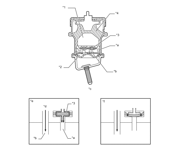
Text in Illustration *1 Main Liquid Chamber *2 Sub Liquid Chamber *3 Movable Membrane *4 Rubber Mount *a Orifice (2) *b Orifice (1) *c Front Engine Mounting Cross Section *d Liquid Flow *e While Idling (Low Vibrations) *f While Driving (High Vibrations)
-
-