ТОПЛИВНАЯ СИСТЕМА
-
CONSTRUCTION
-
Fuel Pump Assembly
-
A fuel pump that has an integrated fuel filter and sender gauge is used.
-
The fuel pump is installed in the fuel tank. The fuel pump is integrated with fuel filter, a sender gauge and a pressure regulator that sends fuel, which is pressurized to 400 kPa, to the engine.
-
A low-current fuel pump is used to minimize power consumption and improve fuel economy.
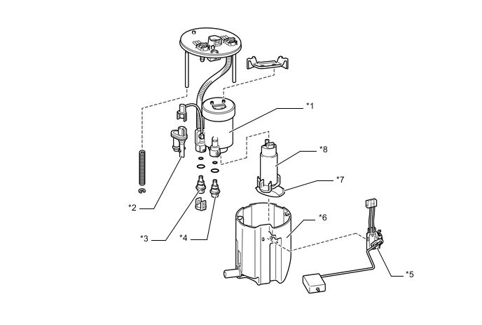
Text in Illustration *1 Fuel Filter Assembly *2 Jet Pump *3 Fuel Main Valve *4 Fuel Pressure Regulator Assembly *5 Sender Gauge *6 Reservoir Cup *7 Suction Filter *8 Fuel Pump
-
-
Fuel Delivery Pipe Sub-assembly
-
Stamped steel delivery pipes are used to deliver fuel to the fuel injectors.
-
An inner pipe inside the delivery pipe is used to absorb fuel pulsations. This eliminates the use of the pulsation damper provided on the conventional models, making the fuel system more compact and lightweight. When fuel pulsates, the shape of the inner pipe changes with the pulsation, thus changing the internal capacity of the delivery pipe. This change in capacity absorbs the fuel pulsations.
-
The wiring harnesses that connect to the injectors are combined into a single strand at each bank. Furthermore, the wiring harnesses connect to the ECM at a single connector for improved serviceability.
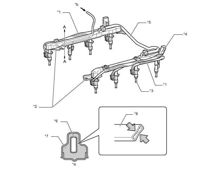
Text in Illustration *1 Wiring Harness *2 Fuel Delivery Pipe Sub-assembly *3 Fuel Injector Assembly *4 Connector *5 Coupling Fuel Pipe *6 Inner Pipe *7 Fuel *8 Inner Pipe (for Absorbing Pulsation) *a A - A Cross Section (Delivery Pipe) *b Fuel (from Fuel Tank)
-
-
Fuel Injector Assembly
-
Compact and lightweight 12-hole type injectors are used as fuel injectors.
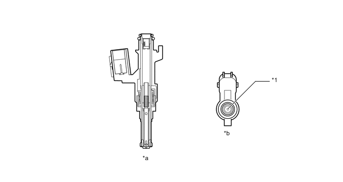
Text in Illustration *1 Injection Nozzle - - *a Cross Section *b View from Bottom Side
-
-
Fuel Tank Assembly
-
A fuel tank assembly made of steel is used.
-
Drain marks have been provided at the lowest position of the fuel tank. When dismantling (scraping) the vehicle, drain fuel by drilling holes at the drain mark.
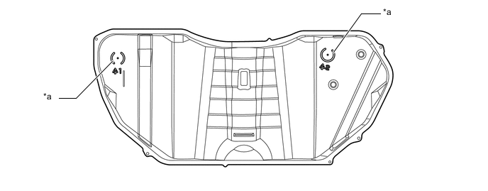
Text in Illustration *a Drain Mark - - -
The fuel tank uses a saddle shape to allow the propeller shaft to pass under the center portion of the tank. Also, a jet pump is used to transfer the fuel from the side of the tank without the fuel pump to the side with the fuel pump.
-
A jet pump is used in the fuel tank. The propeller shaft is located below the raised center of the bottom of the fuel tank. The fuel tank is shaped as indicated below.
-
A fuel tank with such a shape tends to cause fuel to be present in both chamber A and chamber B when the fuel level is low. This stops the fuel in chamber B from being pumped out. To prevent this from occurring, a jet pump is provided to transfer the fuel from chamber B to chamber A.
-
This is accomplished by utilizing the flow of the fuel through the jet pump, so that the pressure difference created by the fuel as it passes through the venturi is used to suck the fuel out of chamber B and send it to chamber A.
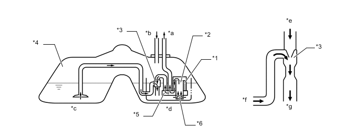
Text in Illustration *1 Fuel Filter *2 Fuel Pump *3 Jet Pump *4 Fuel Tank Assembly *5 Fuel Main Valve *6 Suction Filter *a To Engine *b From Engine *c Chamber B *d Chamber A *e From Fuel Main Valve *f From Chamber B *g To Chamber A (Reservoir Cup) - -
-
-