ELECTRIC POWER CONTROL SYSTEM
-
OPERATION
-
Charging Control
-
This control lowers the generated voltage when the vehicle is idling or is being driven at a constant speed, and raises the generated voltage when the vehicle is decelerating. This reduces the load on the engine as a result of the electric generation of the generator, thus contributing to the fuel economy of the engine. During acceleration, this system regulates the generated voltage in order to place the amperage estimation value close to the target value.
-
This system primarily consists of an ECM, generator, electric power control ECU, battery current sensor, and battery temperature sensor.
-
The electric power control ECU detects the state of charge and discharge of the battery based on the battery voltage and the signals from the battery current sensor and battery temperature sensor. Then, the ECU calculates the accumulated amperage and sends a charging control request signal to the ECM.
-
Based on the charging control request signal from the electric power control ECU, the signals from various sensors and switches and the charging state signal from the generator, the ECM outputs signals to the generator (IC regulator). Thus, the ECM controls the generated voltage to be optimal for the driving condition.
-
Under the following conditions, the electric power control ECU sends a request signal to the ECM so that the ECM stops charging control and switches the generator to normal power generation mode:
-
Various electrical loads are input.
-
Failures of various sensors and switches are detected.
-
-
Battery Current Sensor
-
This sensor detects the charging and discharging amperage of the battery and sends a signal to the electric power control ECU. Based on this signal, the electric power control ECU calculates the battery capacity. A Hall IC is used for detecting the charging and discharging amperage. The changes that occur in the magnetic flux density in the core as a result of the charging and amperage of the battery are converted and output as voltage.
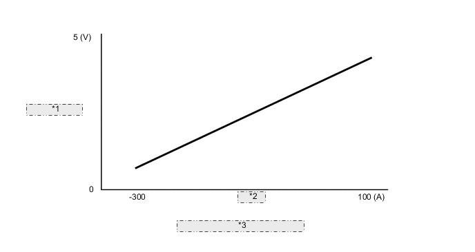
*1 Output Voltage *2 Current *3 Characteristic of Current Sensor
-
-
Battery Temperature Sensor
-
The battery temperature sensor is built into the battery current sensor. The battery characteristic (battery internal resistance) of taking in current for charging varies in accordance with battery electrolyte temperature. If the electrolyte temperature is too low or too high, the battery internal resistance increases, resulting in early deterioration. To prevent this, the battery temperature sensor changes its resistance as shown below to detect the temperature:
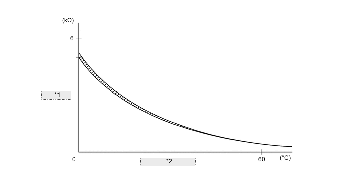
*1 Resistance *2 Battery Temperature
-
-
-
Load Control
-
When the power generation capacity of the vehicle decreases and a large amount of power is consumed, or when the battery is low, load control activates to supply power constantly so that safety-related systems function properly. When the engine is in operation, load control temporarily limits operations of systems that require a large amount of power, such as the air conditioning system, to optimize the battery charge condition. Systems can function normally when the battery charge condition returns to normal.
-
The battery voltage detection line is specified for the electric power control ECU to enhance the accuracy of battery voltage control.
-
If sensors malfunction or communication errors occur, load control is suspended.
-
-
Control While Parked
-
If the vehicle has been parked for a long time, the electric power control ECU judges the elapsed parking time and stops the power supply to systems that are not required to operate during parking, thus extending the battery life. The ECU supplies power to the systems when the driver gets in the vehicle.
-
The power cut relay is built into the electric power control ECU to reduce a parasitic current.
-
-
Combination Meter Assembly
-
When any malfunction of the charging systems and battery of the electric power control system is detected or when under load control, the combination meter warns the driver through the buzzer, the master warning light illumination and the warning message on the multi-information display.
-
The warning messages are described in the table below:
Condition Multi-information Display Master Warning Light Multi Buzzer Generator malfunctions Check Generator (Have your vehicle checked by a dealer) - Sounds Charging line of generator is off Battery voltage drops when power source is turned on (ACC) during parking Low Battery (Start the engine) Illuminates - Abnormal battery voltage Check Power Control System (Have your vehicle checked by a dealer) - - Under load control Electrical equipment operation is limited - -
-
-
-
DIAGNOSIS
-
If the electric power control ECU detects a malfunction in the electric power control system, it stores 5-digit Diagnostic Trouble Code (DTC) in memory.
-
The 5-digit DTC can be read by connecting a Global TechStream (GTS) to the DLC3.
-