PRE-CRASH SAFETY SYSTEM(w/ Driver Monitor Camera)
-
FUNCTION OF MAIN COMPONENTS
Item Function Combination Meter Assembly PCS Warning Light Illuminates or flashes to warn the driver in accordance with signals from the seat belt control ECU. Multi-information Display Displays a warning message to inform or warn the driver of the system condition in accordance with signals from the seat belt control ECU. Master Warning Light Illuminates to warn the driver in accordance with signals from the seat belt control ECU. Multi Buzzer Sounds to warn the driver in accordance with signals from the driving support ECU assembly when the system is malfunctioning. Millimeter Wave Radar Sensor Assembly Radiates the millimeter wave radar forward, uses the reflected millimeter wave for detecting the presence of a vehicle ahead, the vehicle-to-vehicle distance and the relative speed, and then transmits this information to the driving support ECU assembly. Rear Millimeter Wave Radar Sensor Assembly Radiates the millimeter radio wave radar to the rear, uses the reflected millimeter radio waves for detecting the presence of a vehicle being driven behind, the vehicle-to-vehicle distance and the relative speed. Then, the rear millimeter wave radar sensor assembly transmits these pieces of information to the driving support ECU assembly. Front Seat Outer Belt Assembly Seat Belt Motor Retracts the seat belt in accordance with signals received from the seat belt control ECU. Front Seat Inner Belt Assembly (Driver) Buckle Switch Detects the condition (verifies if the belt is fastened) of the driver seat belt and transmits a signal to the center airbag sensor assembly. Front Seat Inner Belt Assembly (Passenger) Buckle Switch Detects the condition (verifies if the belt is fastened) of the front passenger seat belt and transmits a signal to the center airbag sensor assembly. Center Airbag Sensor Assembly Transmits the condition (fastened or unfastened) of the driver and front passenger seat belts to the seat belt control ECU. Driving Support ECU Assembly
-
Makes judgments on whether a collision is unavoidable based on the information received from the millimeter wave radar sensor assembly and object recognition ECU. It then outputs a seat belt operation signal and brake assist standby request signal and pre-crash brake request signal if required.
-
Makes a judgment that a collision is unavoidable based on information received from the rear millimeter wave radar sensor assembly. Then, it outputs a hazard warning light flashing request signal and a pre-crash intelligent headrest operation signal.
Seat Belt Control ECU Receives a seat belt operation request signal from the driving support ECU assembly or skid control ECU assembly and operates the seat belts. Brake Actuator Assembly Brake Actuator Assembly Actuates the brakes in accordance with the signals from the skid control ECU assembly. Master Cylinder Pressure Sensor Detects the master cylinder pressure and transmits a signal to the skid control ECU assembly. Wheel Cylinder Pressure Sensor Detects the wheel cylinder pressure and transmits a signal to the skid control ECU assembly. Skid Control ECU Assembly
-
Receives a brake assist standby request signal from the driving support ECU assembly and switches the brake assist to standby mode. When a stop light switch assembly signal is input, the skid control ECU assembly activates the brake assist.
-
Operates the pre-crash brake if the skid control ECU assembly receives a pre-crash brake operation request signal from the driving support ECU assembly.
-
Receives the warning brake activation request signal from the driving support ECU assembly and operates the warning brake.
-
Determines if the brakes have been applied suddenly through signals received from the master cylinder pressure sensor, and outputs a seat belt operation signal to the seat belt control ECU.
-
Determines the occurrence of a front or rear wheel skid tendency, and outputs a seat belt operation signal to the seat belt control ECU.
-
Transmits vehicle speed signals to the driving support ECU assembly.
Steering Control ECU* Upon receiving a VGRS control request signal from the driving support ECU assembly, the steering control ECU sets the VGRS control to the standby condition and then changes the steering gear ratio when the driver starts to turn the steering wheel to enhance vehicle response. Suspension Control ECU Upon receiving an air suspension control request signal from the driving support ECU assembly, the suspension control ECU optimizes the amount of dampening of the suspension shock absorbers in order to suppress nose-diving during braking and rolling during steering. Object Recognition Camera Uses 2 CCD cameras that support near-infrared photography to detect 3-dimensional objects and transmits image information to the object recognition ECU. Near-infrared Projector Uses filters that are built into the near-infrared projector of the headlight assembly to radiate near-infrared rays. The near-infrared rays enable the object recognition camera to capture image data even at night. Object Recognition ECU Detects the horizontal position of the three-dimensional object based on 2 pieces of image data provided by the object recognition camera, and transmits information to the driving support ECU assembly. Front Controller (Multiplex Network Front Light ECU) Illuminates the near-infrared projector inside the headlight assembly. Driver Monitor Camera The driver monitor camera monitors the face and eyelid of the driver and sends image data to the driver monitor ECU assembly. Driver Monitor ECU Assembly The direction of the driver's face and eyelids are judged in accordance with the data received from the driver monitor camera and the data is sent to the driving support ECU assembly. Stop Light Switch Assembly Detects if the brake pedal is depressed and transmits a signal to the skid control ECU assembly. Speed Sensor Detects speed of each wheel and transmits the signals to the skid control ECU assembly. Yawrate Sensor Detects the yaw rate and lateral/longitudinal deceleration of the vehicle and transmits a signal to the skid control ECU assembly and the driving support ECU assembly. Steering Sensor Detects the angle and direction of steering and transmits a signal to the skid control ECU assembly and the driving support ECU assembly. Precrash System Cancel Switch Assembly Disables the pre-crash brake operation when the switch is turned on. The PCS warning light illuminates to show that the pre-crash brakes off. Skid Control Buzzer Assembly Sounds to warn the driver in accordance with signals from the skid control ECU assembly.
-
*: Models with VGRS system
-
-
OPERATING CONDITION
-
The pre-crash safety system operates in the following components. The components which reduce impact are as shown below:
Impact Dampening Component Operation Condition Pre-crash Warning Control
-
Engine switch is on (IG).
-
Precrash system cancel switch is not pushed.
-
Vehicle speed is approx. 5 km/h (4 mph) or above.
-
Oncoming vehicle relative speed is approx. 5 km/h (4 mph) or above.*1
-
Oncoming vehicle relative speed is approx. 15 km/h (10 mph) or above.*2
Pre-crash Alert Brake Control
-
Engine switch is on (IG).
-
Precrash system cancel switch is not pushed.
-
Driver is not facing forward or eyelids are not open.
-
The object targeted as a potential collision is the vehicle ahead.
-
Vehicle speed is approx. 40 km/h (25 mph) or above.
-
Oncoming vehicle relative speed is approx. 40 km/h (25 mph) or above.
-
Pre-crash Brake Assist Control
-
VGRS Operation*3
-
Engine switch is on (IG).
-
Precrash system cancel switch is not pushed.
-
VSC OFF Switch is not pushed.
-
Vehicle speed is approx. 30 km/h (20 mph) or above.
-
Oncoming vehicle relative speed is approx. 30 km/h (20 mph) or above.
Pre-crash Seat Belt Control (Sudden Brake or Serious Vehicle Skid Control in Conjunction)
-
Engine switch is on (IG).
-
Precrash system cancel switch is not pushed.
-
Seat belt is buckled.
-
Brakes are suddenly applied.
-
System determines a loss of vehicle control.
-
Vehicle speed is approx. 30 km/h (20 mph) or above.
-
Pre-crash Seat Belt Control (Operate in Conjunction with Radar)
-
Air Suspension Control*4
-
Engine switch is on (IG).
-
Precrash system cancel switch is not pushed.
-
Vehicle Speed is approx. 30 km/h (20 mph) or above.
-
Oncoming vehicle relative speed is approx. 30 km/h (20 mph) or above.
Pre-crash Brake Control*5
-
Engine switch is on (IG).
-
VSC OFF switch is not pushed.
-
Precrash system cancel switch is not pushed.
-
Vehicle Speed is approx. 5 km/h (4 mph) or above.
-
Oncoming vehicle relative speed is approx. 5 km/h (4 mph) or above.*1
-
Oncoming vehicle relative speed is approx. 15 km/h (10 mph) or above.*2
Intelligent Headrest Control
-
Engine switch is on (IG).
-
Vehicle is not reversing.
-
Precrash system cancel switch is not pushed.
-
VSC OFF switch is not pushed.
-
Relative vehicle speed is approx. 15 km/h (10 mph) or above.
-
*1: Except models for China
-
*2: Models for China
-
*3: Models with VGRS system
-
*4: Models with air suspension system
-
*5: Models with pre-crash brake control
-
-
If precrash system cancel switch assembly is turned on, pre-crash safety system does not operate.
-
-
SYSTEM CONTROL
-
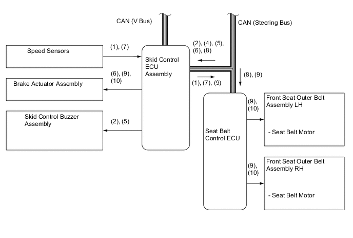
Loss of Vehicle Control
(1) While the vehicle is traveling at approx. 30 km/h (20 mph) or more, the skid control ECU assembly determines if skid recovery will be difficult based on the signals from the steering sensor, yawrate sensor and speed sensors. (2) The skid control ECU assembly sends a seat belt operation request signal to the seat belt control ECU. (3) The seat belt control ECU determines the seat belt motor operating conditions based on this signal and seat belt buckle switch signals. Then, the seat belt control ECU retracts the slack in the seat belts by operating the seat belt motors. (4) The seat belts return to a normal state when the relevant conditions of the vehicle have stabilized. 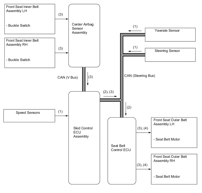
-
Sudden Braking
(1) While the vehicle is traveling at approx. 30 km/h (20 mph) or more, the skid control ECU assembly can determine a sudden braking condition based on the signals from the master cylinder pressure sensor, stop light switch assembly and speed sensors. (2) At this time, the skid control ECU assembly outputs a seat belt operation request signal to the seat belt control ECU. (3) The seat belt control ECU determines the seat belt motor operating conditions based on this signal and seat belt buckle switch signals. Then, the seat belt control ECU retracts the slack in the seat belts by operating the seat belt motors. (4) The seat belts return to a normal state when the brake pedal is released. 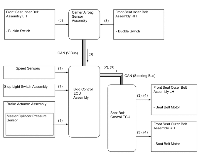
-
High Possibility of Collision or Unavoidable Collision
-
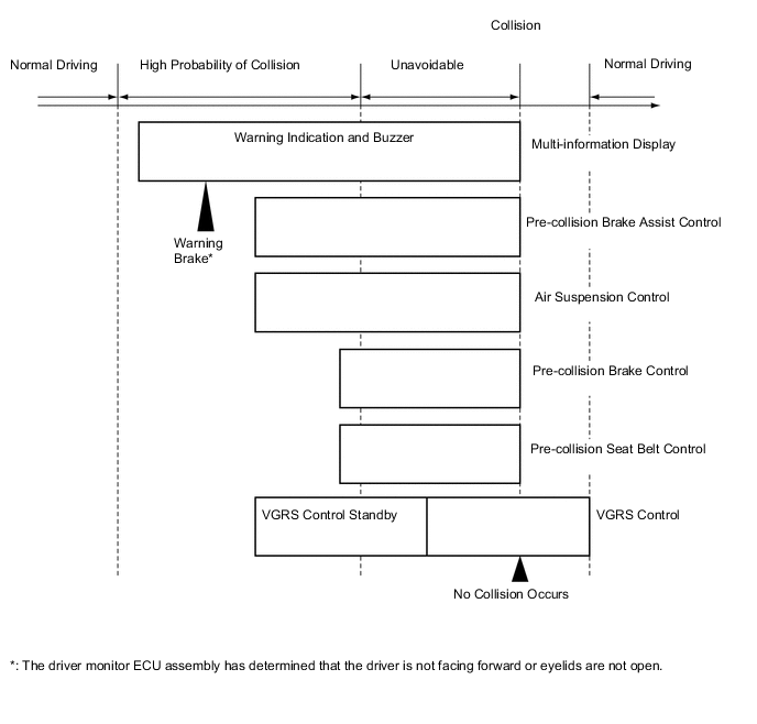
The diagram below shows the flow of the activation of the systems during a pre-crash safety system operation:
-
Operation
(1) The driving support ECU assembly determines that the possibility of a collision is high based on the signals received from the millimeter wave radar sensor assembly, object recognition camera, steering sensor, speed sensors and yawrate sensor. (2) At this time, the driving support ECU assembly outputs a caution display request signal to the multi-information display (combination meter assembly) and a skid control buzzer assembly request signal to the skid control ECU assembly. (3) If the driver monitor ECU assembly determines that the driver fails to face forward or eyelids are not open based on a signal from the driver monitor camera, it transmits this information to the driving support ECU assembly. (4) Upon receiving this signal, the driving support ECU assembly outputs a warning brake operation request signal to the skid control ECU assembly. (5) When the driving support ECU assembly determines that the possibility of an unavoidable collision is high as in step 1, it outputs a brake warning display request signal to the multi-information display (combination meter assembly) and a skid control buzzer request signal to the skid control ECU assembly. (6) At this time, the driving support ECU assembly outputs an air suspension control request signal to the suspension control ECU, a steering control standby request signal to the steering control ECU, and a pre-crash brake assist request signal to the skid control ECU assembly. Upon receiving this signal, the skid control ECU assembly switches the brake assist to the standby condition, and the steering control ECU switches the VGRS control to the standby condition. (7) The driving support ECU assembly determines that an unavoidable collision condition exists based on the signals received from the millimeter wave radar sensor assembly, object recognition camera, speed sensors, steering sensor and yawrate sensor. (8) At this time, the driving support ECU assembly outputs a seat belt operation request signal to the seat belt control ECU and a pre-crash brake request signal to the skid control ECU assembly. (9) The seat belt control ECU determines the seat belt motor operation condition based on this signal and the seat belt buckle switch signal, and retracts the slack in the seat belts by operating the seat belt motors. At the same time, the skid control ECU assembly activates the brake actuator assembly as a pre-crash brake control. (10) If no collision occurs, the seat belts, the brake assist, VGRS and air suspension returns to their normal states. 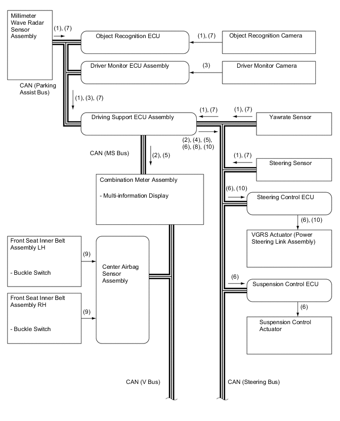
-
-
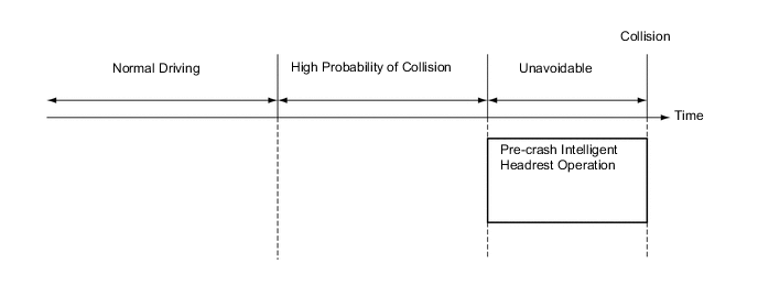
Pre-crash Intelligent Headrest Control
-
The diagram below shows the flow of the activation of the systems during a pre-crash intelligent headrest operation:
-
Operation
(1) The driving support ECU assembly determines that a collision with a vehicle approaching from behind is unavoidable using the signals received from the following sensors: rear millimeter wave radar sensor assembly, speed sensor (skid control ECU assembly) and yawrate sensor. (2) At this time, the driving support ECU assembly transmits a pre-crash intelligent headrest operation signal to the pre-crash intelligent headrest ECU. (3) The pre-crash intelligent headrest ECU operates a motor that is built into the pre-crash intelligent headrest in order to move the front surface of the headrest forward and upward. (4) As the front surface of the headrest moves forward and upward, the head position detection sensor that is built into the pad detects the electrostatic capacity between the headrest and the head of the driver or front passenger. Then, the sensor transmits this information to the pre-crash intelligent headrest ECU. (5) The pre-crash intelligent headrest ECU determines the distance between the front surface of the headrest and the head of the driver or front passenger based on the electrostatic capacity transmitted by the head position detection sensor. Then, the pre-crash intelligent headrest ECU stops the front surface of the headrest in preparation for the rear-end collision. (6) The pre-crash intelligent headrest ECU maintains the position of the front surface of the headrest for approximately 0.9 seconds in preparation for the rear-end collision. After that, the pre-crash intelligent headrest ECU operates the motor inside the pre-crash intelligent headrest to retract the front surface of the headrest. 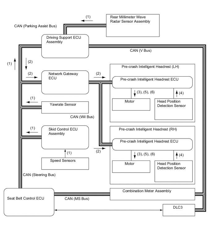
-
-
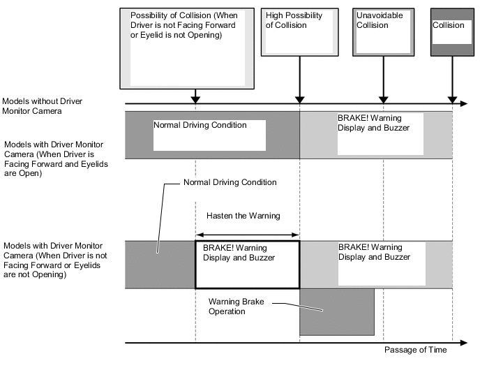
Opening or Closing of Eyelids and Face Direction Determination
-
On models with a driver monitor camera, if the driver monitor ECU assembly detects that the driver is not facing forward or does not have eyelids open, a warning is emitted by the driving support ECU assembly.
-
After the warning, if the driver's condition has not changed, the driving support ECU assembly activates the warning brake operation.*
-
*: The object targeted as a potential collision is the vehicle ahead.
-
-
-
-
FUNCTION
-
Warning Messages Displayed in Combination Meter Assembly
-
The combination meter assembly uses the master warning light, PCS warning light, multi buzzer and multi-information display to provide the driver with pre-crash safety system warnings and indications.
-
If the driving support ECU assembly determines that there is a possibility of a collision, it sends a signal to the combination meter assembly. Upon receiving this signal, the combination meter assembly indicates a warning on the multi-information display, master warning light and PCS warning light. The details are indicated below.
-
If the driving support ECU assembly determines that the possibility of a collision is high, it sends a signal to the combination meter assembly. Upon receiving this signal, the combination meter indicates a warning on the multi-information display, master warning light, PCS warning light and sounds the skid control buzzer assembly. The details are indicated below:
When there is a high possibility of a collision Multi-information Display Detail Skid Control Buzzer Assembly 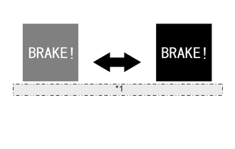
*1 The background of the message on the multi-information display flashes at 0.2-second intervals. The driving support ECU assembly has determined that the possibility of a collision is even higher than the above. Sounds Continuously -
The 3 types of warning messages are used for the pre-crash safety system as described below. The pre-crash safety system does not operate when these messages appear in the combination meter assembly.
Multi-information Display Detail Master Warning Light PCS Warning Light Multi Buzzer DTC 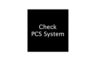
This message appears when the seat belt control ECU detects a system malfunction. Illuminates Illuminates Sounds Once ○ 
This message appears when the seat belt control ECU determines that any of the following conditions exist:
-
Dirty millimeter wave radar sensor assembly
-
Poor weather condition
-
Overheated seat belt control ECU
-
Dirty object recognition camera
-
Dirty driver monitor camera
After these conditions have been resolved, the system will operate normally.
Illuminates Flashes Sounds Once X 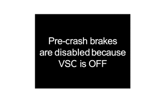
This message appears when the VSC OFF switch has been pushed.
The message is displayed for 3 seconds after the VSC OFF switch is operated.
- - - X Tech Tips
○ : Repair is required/DTCs are output
X: Repair is not required/DTCs are not output
-
-
-
-
CONSTRUCTION
-
Millimeter Wave Radar Sensor Assembly
-
The millimeter wave radar sensor assembly consists of a millimeter wave radar circuit signal processing circuit, and CPU.
-
The millimeter wave radar outputs waves when the vehicle speed is above 0 km/h (0 mph), and not when the vehicle speed is at 0 km/h (0 mph). The millimeter wave radar uses frequencies in the 76.5 GHz band.
-
The reception antennas receive the millimeter wave radar waves that have been reflected.
-
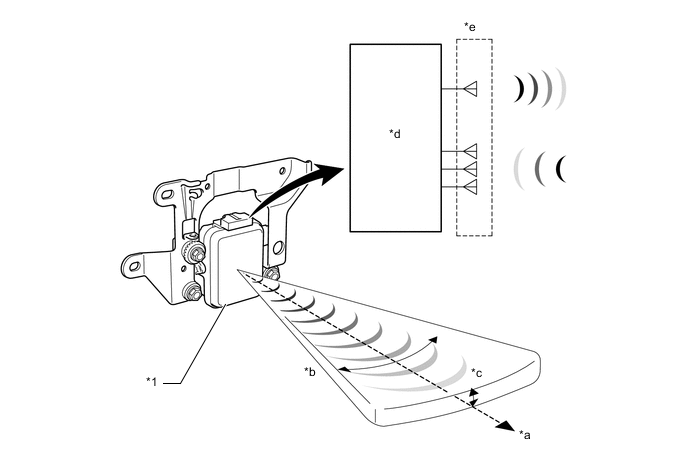
The signal processing circuit detects the distance, relative speed and the direction of the object by generating millimeter wave radar waves and calculating the signals received by the reception antennas. Then, the signal processing circuit transmits this information to the driving support ECU assembly.
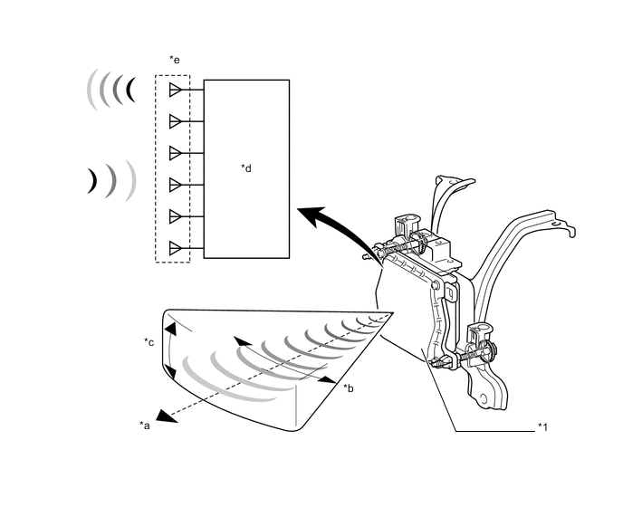
Text in Illustration *1 Millimeter Wave Radar Sensor Assembly - - *a Detection Distance: Approx. 150 m (490 ft.) *b Horizontal Angle: Approx. 20° *c Vertical Angle: Approx. 8° *d Signal Processing Circuit *e Millimeter Wave Radar Circuit - - -
The distance to the object, azimuth (horizontal angle) and relative speed are calculated from the information that is provided by the reflection millimeter wave radar as described below:
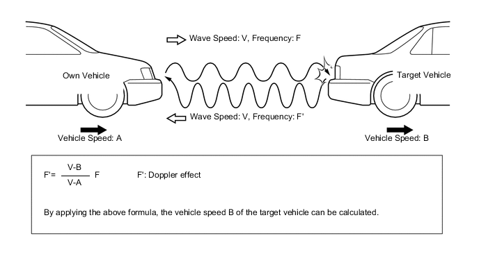
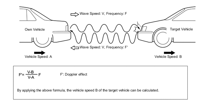
Item Calculation Method Distance Calculated from the length of time that has elapsed from the time the waves of the millimeter wave radar have been emitted, until the waves reflected by the millimeter wave radar are received. The detection distance is approx. 150 m (490 ft.). Azimuth Calculated from the angle of the waves reflected by the millimeter wave radar that have been received. The detection angle has a horizontal angle of approx. 20° and a vertical angle of approx. 8°. Relative Speed Calculated by utilizing the changes (Doppler effect*) that occur in the frequencies of the reflected millimeter wave radar waves. Tech Tips
*: The Doppler effect causes the observer to perceive the radio waves emitted by a moving object to be of higher frequencies as it approaches, and to be of lower frequencies as it recedes.
-
-
Rear Millimeter Wave Radar Sensor Assembly
-
The rear millimeter wave radar sensor assembly consists of a rear millimeter wave radar circuit, signal processing circuit and CPU.
-
The rear millimeter wave radar circuit consists of an antenna (used for both transmission and reception) and reception antennas.
-
The rear millimeter wave radar sensor assembly uses frequencies in the 76 GHz band.
-
The reception antennas receive the millimeter wave radar waves that have been reflected.
-
The signal processing circuit detects the distance, relative speed and the direction of the object by generating millimeter wave radar waves and calculating the signals received by the reception antennas. Then, the signal processing circuit transmits this information to the driving support ECU assembly.
Text in Illustration *1 Rear Millimeter Wave Radar Sensor Assembly - - *a Detection Distance: Approx. 1.6 to 31 m (5.2 to 101.7 ft.) *b Horizontal Angle: Approx. 30° *c Vertical Angle: Approx. 4° *d Signal Processing Circuit *e Rear Millimeter Wave Radar Circuit - - -
The distance to the object, azimuth (horizontal angle) and relative speed are calculated from the information that is provided by the reflection millimeter wave radar as described below:
Item Calculation Method Distance Calculated from the length of time that has elapsed from the time the waves of the rear millimeter wave radar sensor assembly have been emitted, until the waves reflected by the rear millimeter wave radar are received. The detection distance is approx. 1.6 to 31 m (5.2 to 101.7 ft.). Azimuth Calculated from the angle of the waves reflected by the rear millimeter wave radar sensor assembly that have been received. The detection angle has a horizontal angle of approx. 30° and a vertical angle of approx. 4°. Azimuth Calculated by utilizing the changes (Doppler effect*) that occur in the frequencies of the reflected millimeter wave radar waves. Tech Tips
*: The Doppler effect causes the observer to perceive the radio waves emitted by a moving object to be of higher frequencies as it approaches, and to be of lower frequencies as it recedes.
-
-
Near-infrared Projector
-
The near-infrared projector radiates near-infrared rays forward in order to enable the object recognition camera to capture the image of the objects even at night.
-
The near-infrared projector is built into the high beam units of the headlight assemblies.
-
When the conditions indicated below are met, the object recognition ECU transmits a near-infrared illumination request signal to the front controller (multiplex network front light ECU) via the driving support ECU assembly.
-
The engine switch is on (IG).
-
The low beam headlights are on.
-
The light control sensor on the automatic light control system has determined that the surroundings of the vehicle have become dark.
-
The vehicle is being driven [15 km/h (10 mph) minimum]. However, the near-infrared projector turns off when the vehicle comes to a stop [10 km/h (6 mph) maximum].
Text in Illustration *1 Object Recognition Camera - - *a Near-infrared Rays *b Reflected Rays -
-
On except models for China, each high beam unit of the headlights contains a retractable, visible rays cut filter. To serve as an ordinary high beam headlight to radiate visible rays, the visible rays cut filter is retracted. To radiate near-infrared rays, the visible rays cut filter is upright. The light from the bulb passes through the visible rays cut filter so that only the near-infrared rays are emitted. Because the center of the visible rays cut filter forms a prism, the light that passes through the visible rays cut filter diffuses wider than an ordinary high beam headlight. The amount of the radiated energy is also the same as that of a hi beam headlight. This construction enables the system to capture a field of vision that is farther than that of the low beam headlights.
-
On models for China, each near-infrared projector of the headlight assembly contains a visible ray cut filter. The light from the bulb passes through the visible ray cut filter so that only the near-infrared rays are emitted. Because the center of the visible ray cut filter forms a prism, the light that passes through the visible ray cut filter diffuses wider than an ordinary headlight units. This construction enables the system to capture a field of vision that is farther than that of the low beam headlight units.
-
These projectors emit weak visible rays around the lens of the projectors.
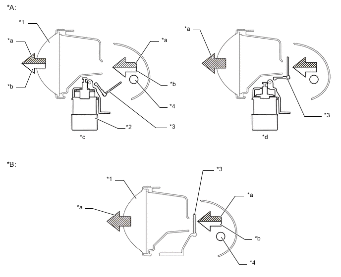
Text in Illustration *A Except Models for China *B Models for China *1 Lens *2 Hi Beam/Near Infrared Rays Switching Solenoid *3 Visible Rays Cut Filter *4 Bulb *a Near-infrared Rays *b Visible Rays *c Operating as Hi Beam *d Operating as Infrared Projector Note
The near-infrared projector emits weak visible rays when the near-infrared rays is emitted. However, do not look directly into the headlight assembly near-infrared projector unit for long time because they radiate the same amount of energy as the high beam headlight.
-
-
Object Recognition Camera
-
The object recognition camera consists of 2 cameras that are placed side-by-side in the center front area of the vehicle's roof headlining. Because these 2 cameras capture the reflected rays of the near-infrared projectors that are built into the headlight assembly, they can capture images even at night.
-
The 2 cameras of the object recognition camera capture an object and transmit the left and right image signals to the object recognition ECU. The object recognition ECU processes those images to detect a three-dimensional form and detects the parallax to calculate the distance to the object.
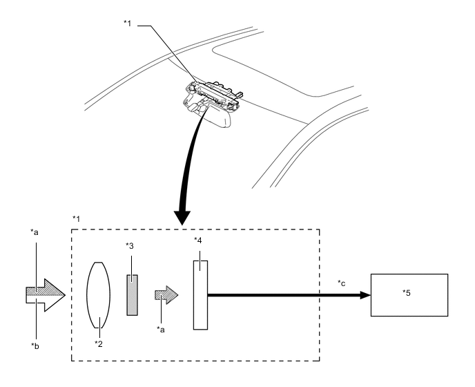
Text in Illustration *1 Object Recognition Camera *2 Lens *3 Visible Rays Cut Filter *4 Charge Coupled Devices (CCD) *5 Object Recognition ECU - - *a Near-infrared Rays *b Visible Rays *c Image Data - - -
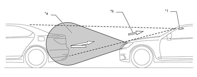
The forward field of vision of the object recognition camera is within the range of approximately 45 degrees of the horizontal field angle and approximately 35 degrees of the vertical field angle.
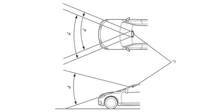
Text in Illustration *1 Object Recognition Camera - - *a Approx. 45° *b Approx. 35°
-
-
Driver Monitor Camera
-
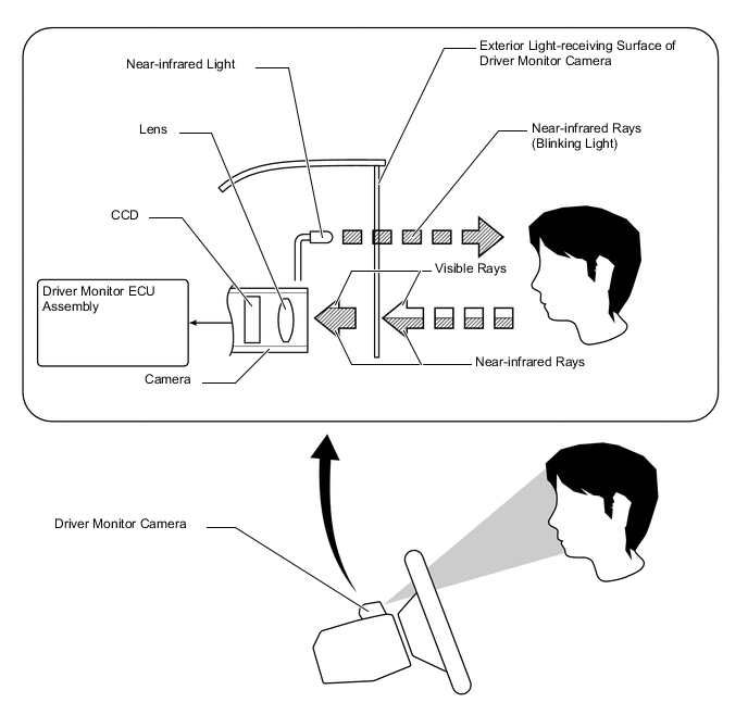
The driver monitor camera, which is mounted on the steering column, monitors the driver's face and eyelids, and transmits image data to the driver monitor ECU assembly.
-
The 2 near-infrared lights that are built into the driver monitor camera illuminate the driver's face and eyelids. Then, the reflected light consists primarily of near-infrared rays after it passes through the exterior light-receiving surface (which is made of a material that suppresses the transmission of visible rays). The CCD receives the reflected light, thus enabling the monitoring of the driver's face and eyelids even in the dark.
-
The 2 near-infrared lights that are built into the driver monitor camera illuminate the driver's face when the system is turned on.
-
-
Driver Monitor ECU Assembly
-
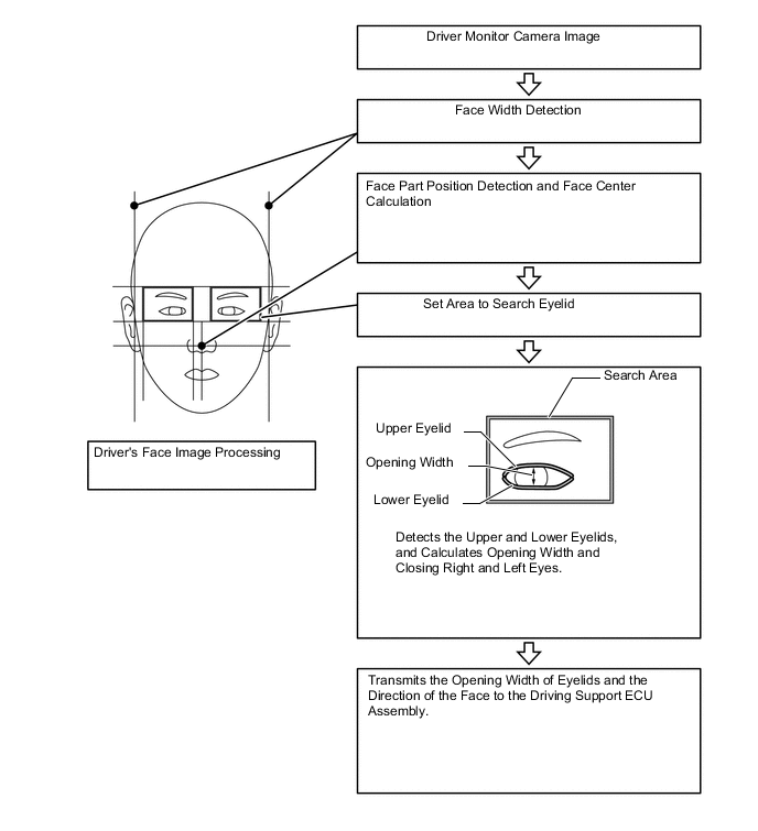
The driver monitor ECU assembly calculates the direction of the driver's face in accordance with the width of the face and the position of the eyes and the mouth, and calculates the open or close condition of the driver's eyelids in accordance with the width of the upper and lower line of eyes, found in the image data received from the driver monitor camera. Then, it transmits a face direction and eyelids open or close condition detection signal to the driving support ECU assembly.
-
-
Pre-crash Intelligent Headrest
-
If the rear millimeter wave radar sensor assembly has determined the possibility of being rear-ended, the front surface of the pre-crash intelligent headrest moves forward and upward. This shortens the distance between the headrest and the head of the driver or front passenger, thus lessening the neck injury sustained by the occupant.
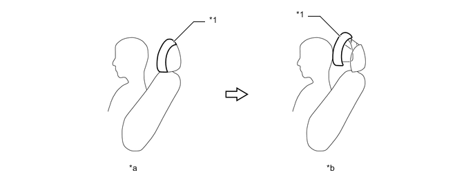
Text in Illustration *1 Pre-crash Intelligent Headrest - - *a Normal Driving *b Unavoidable -
The driver and front passenger seats are equipped with the pre-crash intelligent headrests. The pre-crash intelligent headrest consists of a head position detection sensor, pre-crash intelligent headrest ECU, link mechanism and electric motor.
-
The pre-crash intelligent headrest ECU operates the electric motor to actuate the link mechanism, causing the front part of the headrest to move forward and upward. The maximum movable distance is 60 mm (2.4 in.) forward and 25 mm (1 in.) upward.
-
The head position detection sensors are located in the headrest pads. The sensors detect the positions of the driver's and front passenger's heads using changes in electrostatic capacity* between the head and headrest. When a rear collision is determined to be unavoidable, each built-in head position detection sensor commences detecting the driver's and front passenger's head positions. When a seat is unoccupied, the front part of the relevant headrest moves to its maximum distance, and then comes to a stop. When a seat is occupied, the front part of the relevant headrest moves until it makes contact with the head.
Tech Tips
*: The capacity of an object to store an electric charge. The unit used to represent this capacity is F (Farad).
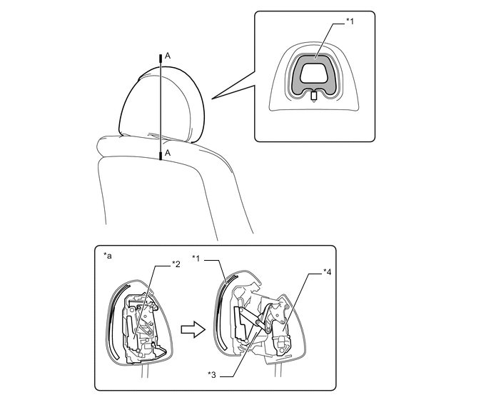
Text in Illustration *1 Head Position Detection Sensor *2 Pre-crash Intelligent Headrest ECU *3 Link Mechanism *4 Motor *a A - A Cross Section - -
-
-