TELEMATICS SYSTEM
Figure 1. Models with G-BOOK
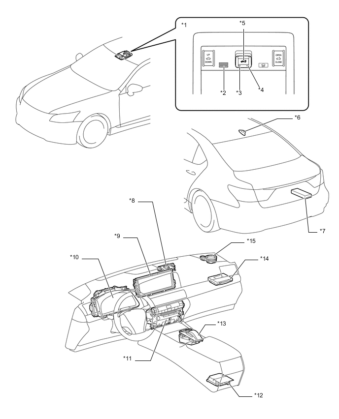
| *1 | Map Light Assembly | *2 | Telephone Microphone Assembly |
| *3 | Indicator Light (Green) | *4 | Indicator Light (Red) |
| *5 | Telephone Switch Assembly | *6 | Telephone Antenna Assembly |
| *7 | Stereo Component Amplifier Assembly | *8 | Navigation Antenna Assembly |
| *9 | Multi-display (Accessory Meter Assembly) | *10 | Combination Meter Assembly |
| *11 | Multi-media Module Receiver Assembly | *12 | Center Airbag Sensor Assembly |
| *13 | Remote Touch | *14 | Telematics Transceiver (DCM) |
| *15 | Front No. 2 Speaker Assembly RH | - | - |
Figure 2. Models with ERA-GLONASS 1
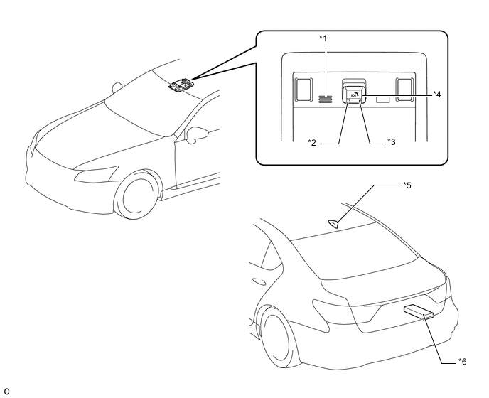
| *1 | Telephone Microphone Assembly | *2 | Manual (SOS) Switch Green Indicator |
| *3 | Manual (SOS) Switch Red Indicator | *4 | Manual (SOS) Switch |
| *5 | Telephone Antenna Assembly | *6 | Stereo Component Amplifier Assembly |
Figure 3. Models with ERA-GLONASS 2
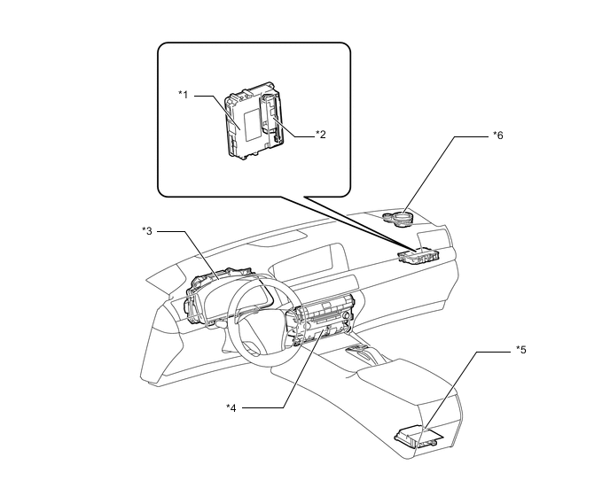
| *1 | Telematics Transceiver (DCM) | *2 | Mobilephone Battery (Back-up Battery) |
| *3 | Combination Meter Assembly | *4 | Multi-meia Module Receiver Assembly |
| *5 | Center Airbag Sensor Assembly | *6 | Front No. 2 Speaker Assembly RH |