ELECTRIC PARKING BRAKE SYSTEM
-
FUNCTION OF MAIN COMPONENTS
Component Function Parking Brake with Bracket Actuator Assembly Motor Winds and unwinds the parking brake cable based on the signals from the parking brake ECU assembly. Tension Sensor Detects the parking brake cable tension. Emergency Release Cable In the case of a failure in the electric parking brake system, the driver can turn the emergency release cable to manually release the parking brake. Electric Parking Brake Switch Assembly Manual Switch Locks the parking brake when the switch is pushed, and releases the parking brake when the switch is pulled. Auto Switch Switches the auto function on and off. Indicator Light Illuminates to inform the driver that auto function is available. Combination Meter Assembly Parking Brake Indicator Light
-
Lights up to inform the driver that the parking brake has locked.
-
Blinks to inform the driver that the electric parking brake system is not available.
Brake System Warning Light (Yellow Indicator) Lights up to inform the driver that the parking brake ECU assembly detected a malfunction in the system. Multi-information Display Informs the driver that the parking brake ECU assembly has a malfunction in the system. Master Warning Light Informs the driver that the parking brake ECU assembly has a malfunction in the system. Multi Buzzer Sounds together with the indication of the multi-information display and the illumination of the master warning light in order to inform the driver of a malfunction in the electric parking brake system. Yawrate Sensor (with Built-in Deceleration Sensor) Detects the gradient of the road surface by detecting the inclination of the vehicle. Parking Brake ECU Assembly Operates the parking brake with bracket actuator assembly to lock and release the parking brake based on the signals from the electric parking brake switch assembly, various ECUs, and sensors. Skid Control ECU Assembly
-
Detects the wheel speed.
-
Determines whether the brake pedal is depressed.
-
Sends a parking brake lock command to the parking brake ECU assembly during brake hold control.
TCM Transmits the shift lever position to the parking brake ECU assembly. -
-
SYSTEM CONTROL
-
Manual Function
-
When the manual switch is pressed while the vehicle is stopped, the parking brake ECU assembly will drive the motor of the parking brake with bracket actuator assembly to lock the parking brake. At this time, the parking brake ECU assembly will calculate the incline of the road surface on which the vehicle is stopped based on signals from the yawrate sensor, control the pulling force of the parking brake cable in accordance with the rotations of the motor, and generate a braking force which is responsive to the road surface on which the vehicle is stopped.
-
When a malfunction occurs in the yawrate sensor signal, the motor of the parking brake with bracket actuator assembly will be controlled in such a way as to generate the largest amount of braking force.
-
When the manual switch is pulled, the parking brake ECU assembly will drive the motor of the parking brake with bracket actuator assembly in the opposite direction, thus releasing the parking brake.
-
When the vehicle is in motion, the motor of the parking brake with bracket actuator assembly will be driven and braking force will be generated only while the manual switch is being pressed. When the manual switch is released, the motor of the parking brake with bracket actuator assembly will be driven in the opposite direction, thus reducing braking force.
-
-
Auto Function
-
When the auto switch is turned on, the parking brake ECU assembly will activate the auto function. When the driver moves the shift lever to P from a position other than P while the auto function is operating, the parking brake ECU assembly will control the rotation of the motor of the parking brake with bracket actuator assembly, thus locking the parking brake.
-
When the shift lever is moved from P to a position other than P while the brake pedal is depressed, the parking brake will be released.
Note
When the shift lever is in P and the parking brake is released, the motor of the parking brake with bracket actuator assembly will not be driven even if the auto switch is turned on, and the parking brake will not be locked.
-
-
-
CONSTRUCTION
-
Parking Brake with Bracket Actuator Assembly
-
The parking brake with bracket actuator assembly is constructed with a motor, each gear, emergency release gear, clutch, shaft, equalizer and tension sensor, and is connected to each cable.
-
When a lock signal is received from the parking brake ECU assembly, the motor will wind up the parking brake cable by rotating the shaft, thus locking the parking brake.
-
When the motor stops rotating, operation of the clutch maintains the pulling force of the parking brake cable.
-
When a release signal is received from the parking brake ECU assembly, the motor turns in the opposite direction to reduce the pulling force of the parking brake cable, thus releasing the parking brake.
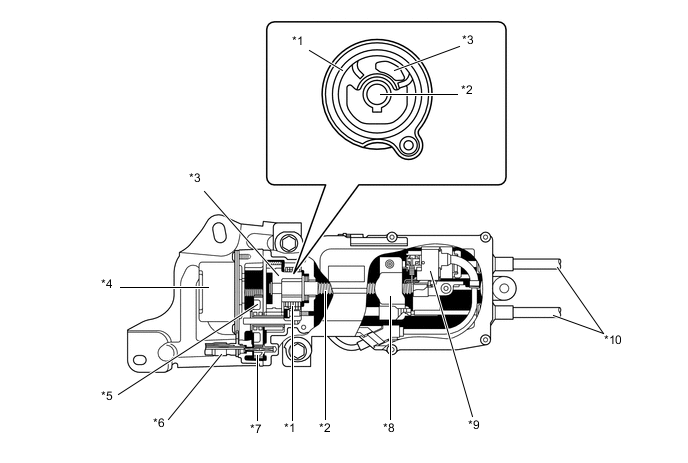
Text in Illustration *1 Clutch *2 Shaft *3 No. 3 Gear *4 Motor *5 No. 2 Gear *6 Emergency Release Cable *7 Emergency Release Gear *8 Equalizer *9 Tension Sensor *10 Parking Brake Cable 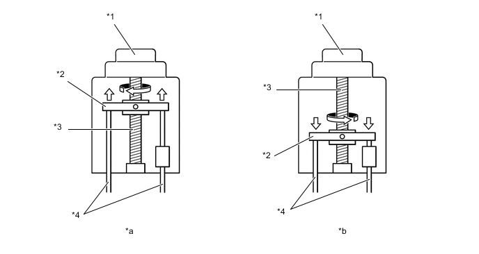
Text in Illustration (Parking Brake with Bracket Actuator Assembly Operation Image) *1 Motor *2 Equalizer *3 Shaft *4 Parking Brake Cable *a Parking Brake Lock *b Parking Brake Release Note
If the electric parking brake system fails, the parking brake can be released manually through the use of a dedicated tool that is onboard the vehicle. To do so, the emergency release cable must be turned counterclockwise while the emergency release cable is pushed. As the emergency release cable is pushed, the rotational movement of the emergency release cable travels to the emergency release gear. Then, the No. 2 and No. 3 gears rotate the shaft in order to loosen the parking brake cable.
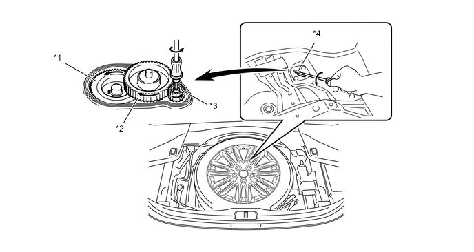
Text in Illustration *1 No. 3 Gear *2 No. 2 Gear *3 Emergency Release Gear *4 Emergency Release Cable
-
-
Tension Sensor
-
A Hall IC type height control sensor has been provided. This sensor is connected to the equalizer in order to detect the motion of the parking brake cable.
-
When the equalizer is pulled to the left (as shown in the illustration below) due to the motor operating, the shaft and built-in magnet are also moved in the same direction.
-
When the shaft is moved to the left, causing the case to be moved in the same direction via the springs. Thus, the parking brake cable is pulled.
-
The springs compress in accordance with the tension acting on the parking brake cable, causing the positions of the case and magnet to change. As a result, the magnetic flux density changes. Hall ICs detect changes in the magnetic flux density, convert those changes into electrical signals, and then transmit them to the parking brake ECU assembly. Based on the signals received from Hall ICs, the parking brake ECU assembly calculates the tension of the parking brake cable.
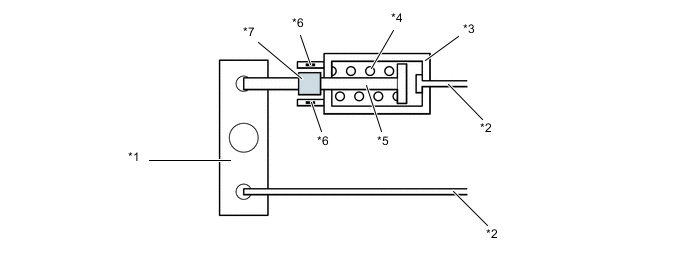
Text in Illustration (Parking Brake with Bracket Actuator Assembly Operation Image) *1 Equalizer *2 Parking Brake Cable *3 Case *4 Spring *5 Shaft *6 Hall IC *7 Magnet - -
-
-
Electric Parking Brake Switch Assembly
-
When the driver presses the manual switch, the parking brake becomes locked and pulling the manual switch releases the parking brake.
-
When the auto switch is turned on, the parking brake ECU assembly changes to auto function. At this time, the indicator light in the auto switch illuminates to inform the driver that auto function is available.
-
Even if the auto switch is pressed while the auto function cannot be executed, the indicator light in the auto switch will not turn on.
-
-
-
FAIL-SAFE
-
When a malfunction has occurred in the system, the manual function maintains as much control as possible.
-
When a malfunction has occurred in the system, the auto function bans control. In addition, control of the auto function is maintained while the electric parking brake switch assembly is malfunctioning.
-
When a malfunction has occurred with the parking brake locked, the locked parking brake can be released manually using the emergency release cable.
-
-
DIAGNOSIS
-
If a malfunction is detected in the system, the parking brake ECU assembly will alert the driver by illuminating the brake system warning light (yellow indicator) in the combination meter and outputting a warning message on the multi-information display.
-
At the same time, the Diagnosis Trouble Codes (DTCs) are stored in the memory. The DTCs stored in the parking brake ECU assembly are output to a Global TechStream (GTS) connected to the DLC3. For details, refer to the Repair Manual.
-