COOLING SYSTEM
-
CONSTRUCTION
-
Water Pump
-
A rust-resistant water pump rotor made of stainless steel is used.
-
The water pump sends the engine coolant to the engine coolant distribution pathway located between the left and right banks of the engine block.
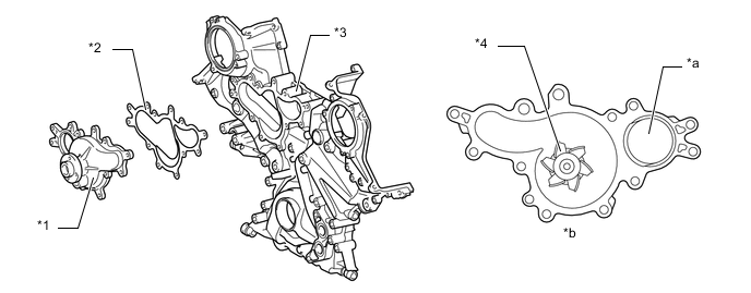
Text in Illustration *1 Water Pump *2 Water Pump Gasket *3 Timing Chain Cover *4 Rotor *a From Water Inlet Housing *b View from Back Side
-
-
Engine Coolant Distribution Pathway
-
The water pump discharges the engine coolant and directs it to the engine coolant distribution pathway located between the left and right banks. From there, the engine coolant is discharged to the cylinder heads and the cylinder block.
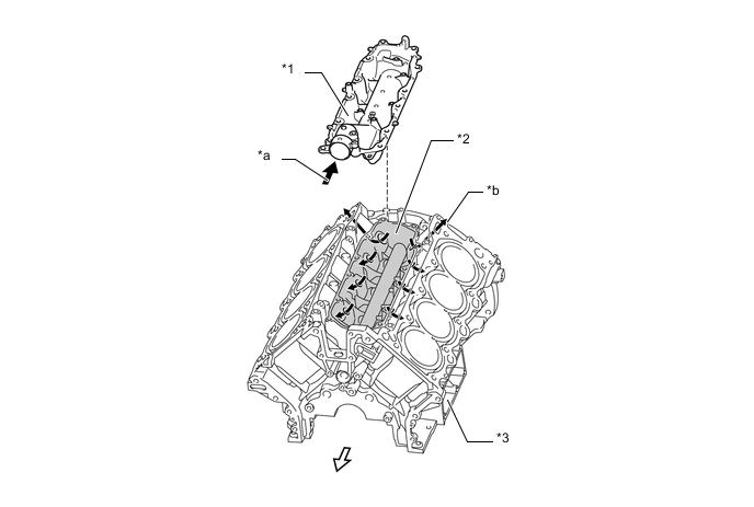
Text in Illustration *1 Heat Exchanger Cover *2 Engine Coolant Distribution Pathway *3 Cylinder Block - - *a From Water Pump *b To Cylinder Head 
Engine Coolant Flow 
Front Side
-
-
Cooling Fan and Fan Shroud
-
The fan shroud is secured to the radiator without the use of bolts to improve serviceability.
-
A ring-shaped electric fan is used to ensure efficient cooling performance and quieter operation.
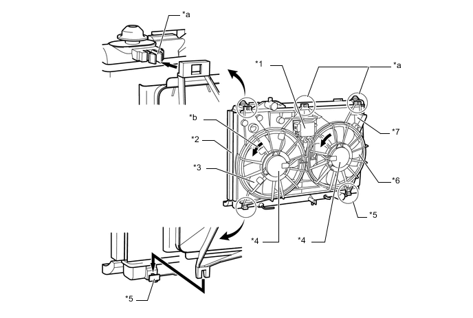
Text in Illustration *1 Cooling Fan ECU *2 Radiator Assembly *3 Main Fan *4 Fan Motor *5 Clip *6 Sub Fan *7 Fan Shroud - - *a Locking Clip *b Fan Rotation Direction
-
-