FUEL SYSTEM
-
OUTLINE
-
The 1UR-FSE engine uses a Direct injection 4-stroke gasoline engine Superior version (D-4S) system which has both direct and port types of injectors.
-
This system optimally controls the injectors for direct injection and port injection in accordance with engine load. The system achieves improved engine performance, fuel economy and clean emissions.
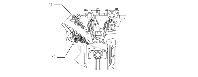
Text in Illustration *1 Fuel Injector Assembly (for Port Injection) *2 Fuel Injector Assembly (for Direct Injection) -
A fuel returnless system, which controls the fuel pressure for the low pressure part of the fuel system using a pressure regulator installed in the fuel tank, is used. However, the unused fuel from the high-pressure fuel pump and the fuel from the relief valve return to the fuel tank.
-
A fuel cut control is used to stop the fuel pump (for low pressure) when an SRS airbag is deployed.
-
In order to ensure excellent serviceability, quick connectors are used to connect the fuel pipe to the fuel hose.
-
High-pressure injectors with double slit nozzles are used for direct injection.
-
An evaporative emission control system is used. For details, see the 1UR-FSE Emission Control.
-
-
MAIN FEATURES
-
D-4S System
-
The D-4S system is based on 2 types of fuel injection systems: the direct injection system and the port injection system. Fuel sent from the fuel tank is delivered to the low-pressure and high-pressure fuel systems. The fuel delivered to the low-pressure fuel system is injected from the injectors (for port injection) to the intake ports. The fuel delivered to the high-pressure fuel system is pressurized by the high-pressure fuel pumps and injected from the injectors (for direct injection) to the combustion chambers.
-
The direct injection system mainly consists of fuel pumps (for high pressure), delivery pipes (for direct injection) and injectors (for direct injection). In this system, the ECM controls the high pressure fuel pumps and direct injection injectors via the injector drivers (Electronic Driver Units: EDUs) based on signals from various sensors, thus optimally controlling fuel pressure, injection volume and injection timing.
-
The port injection system mainly consists of a fuel pump (for low pressure), delivery pipes (for port injection) and injectors (for port injection). In this system, the ECM controls the port injection injectors based on signals from various sensors, thus optimally controlling injection volume and timing.
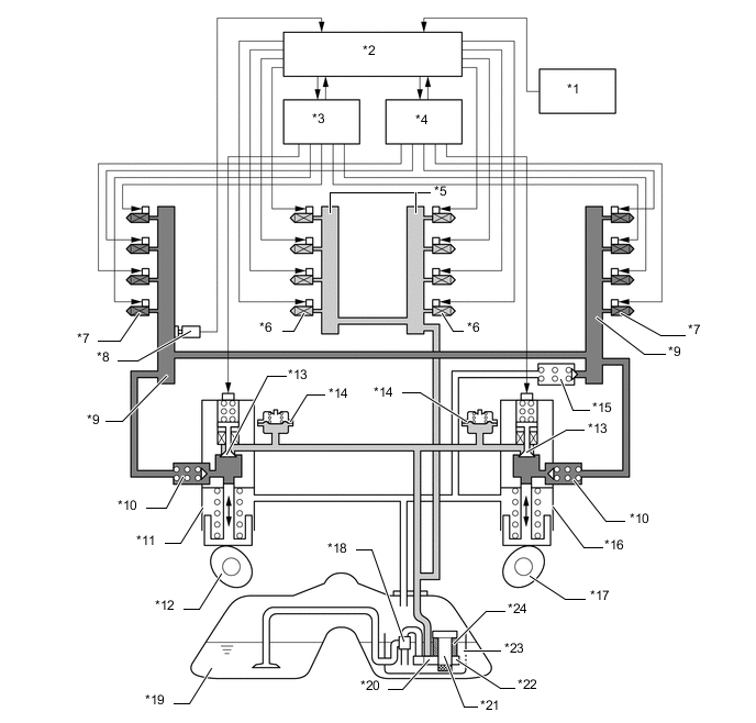
Text in Illustration *1 Various Sensor
- Intake Mass Air Flow Meter Sub-assembly
- Throttle Position Sensor
- Crankshaft Position Sensor
- Engine Coolant Temperature Sensor
- Intake Air Temperature Sensor
*2 ECM *3 Injector Driver (EDU) (for LH Bank) *4 Injector Driver (EDU) (for RH Bank) *5 Fuel Delivery Pipe Sub-assembly (for Port Injection) *6 Fuel Injector Assembly (for Port Injection) *7 Fuel Injector Assembly (for Direct Injection) *8 Fuel Pressure Sensor *9 Fuel Delivery Pipe Sub-assembly (for Direct Injection) *10 Check Valve *11 Fuel Pump LH (for High Pressure) *12 Pump Cam LH (Intake Camshaft) *13 Spill Control Valve *14 Pulsation Damper *15 Relief Valve *16 Fuel Pump RH (for High Pressure) *17 Pump Cam RH (Intake Camshaft) *18 Jet Pump *19 Fuel Tank Assembly *20 Fuel Main Valve *21 Fuel Pump (for Low Pressure) *22 Fuel Pressure Regulator Assembly *23 Reservoir Cup *24 Fuel Filter 
Low-pressure Fuel System 
High-pressure Fuel System
-
-
Fuel Returnless System (for Low Pressure Side)
-
A fuel returnless system is used to reduce evaporative emissions. As shown below, if the fuel filter and pressure regulator are integrated with the fuel pump assembly, it is possible to discontinue the return of fuel from the engine area and reduce the consequent temperature rise inside the fuel tank.
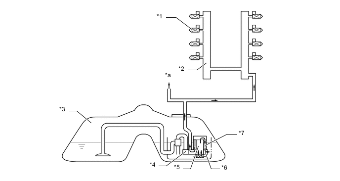
Text in Illustration *1 Fuel Injector Assembly (for Port Injection) *2 Fuel Delivery Pipe Sub-assembly (for Port Injection) *3 Fuel Tank Assembly *4 Fuel Main Valve *5 Fuel Pump *6 Fuel Pressure Regulator Assembly *7 Fuel Filter - - *a High-pressure Fuel Side - -
-
-